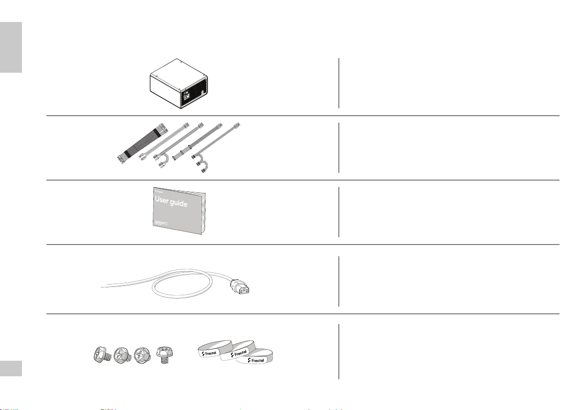
Fractal Ion Gold User manual

ユーザー ガイド
用户指导 使用者指南
Ion Gold
User guide
Anwenderleitfaden / Guide de l’utilisateur /
Guía del usuario / Användarguide /


For more information and product specications, visit
fractal-design.com Safety Information,
Installation & Troubleshooting,
Support
Connectors & Outputs
Introduction
V1.1
EN
RO
TC
PT
DE
BG
SC
KO
FR
HU
SE
TR
ES
HR
RU
RS
JP
IT
CZ
PL
General
Specication Connectors
Outputs

3
Life expectancy (MTBF) at maximum output load 100 000 hours
Power factor correction (PFC) Active
Fan type Dynamic X2 GP-14 Power Supply Edition
Operating temperature 0°C – 40°C, up to 50°C at 80% of full load
Operating humidity 20% - 90%
Protected against Over power
Over voltage
Under voltage
Short circuit
Over current
Over temperature
Effeciency 80PLUS®GoldCertied
Standby power consumption ErP 2013 (<0.45W @ 230 VAC, 45mA load on +5Vsb)
General Specication
Allgemeine Spezikation / Spécication générale / Especicaciones generales / Allmän specikation / Общая спецификация / 一般仕様 / 一般规格 / 一般規格
General
Specication

4
General
Specication
86 mm 150 mm
150mm

5
Package Contents
Packungsinhalt / Contenu de l’emballage / Contenido de la caja / Förpackningsinnehåll / Комплект поставки / パッケージ内容 / 包装内容 / 包裝內容
General
Specication
Power supply / Netzteil / Alimentation électrique / Fuente de alimentación /
Nätaggregat / Источник питания / 電源 / 电源 / 電源
Velcro cable ties and mounting screw pack /
Klettbandverschlüsse und Montageschrauben-Set /
Attaches de câble velcro et paquet de vis de montage /
Sujetacables de velcro y paquete de tornillos de montaje /
Kardborreband och monteringsskruvar /
Кабельные стяжки на липучках и комплект монтажных винтов /
マジックテープ製のケーブルタイと取付ネジのパック /
Velcro电缆扎带和安装螺丝包 / Velcro 纜線紮帶和安裝螺絲包
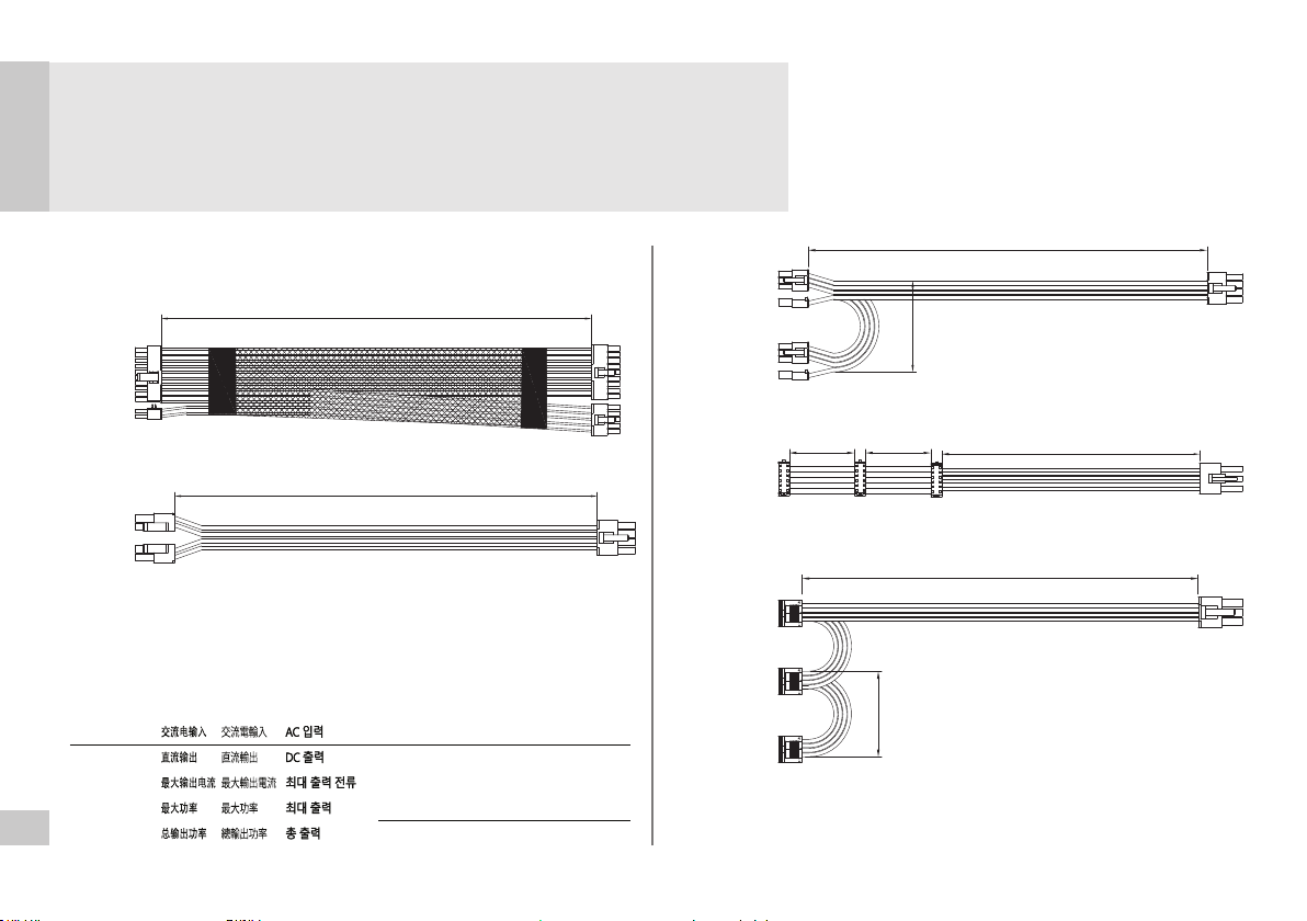
Modular cable kit / Modulares Kabelset / Kit de câble modulaire /
Kit de cableado modular / Modulärkablage /
Комплект отстегивающихся кабелей / モジュール式ケーブルキット /
模块化电缆套件 / 模組化纜線套件
User guide (this booklet) / Benutzerleitfaden (diese Broschüre) /
Guide de l’utilisateur (ce livret) / Guía del usuario (este folleto) /
Användarguide (denna broschyr) / Руководство пользователя (этот буклет) /
ユーザーガイド(本ドキュメント) /
用户指南(本手册) / 使用者指南(本手冊)
AC Power Cord (localized) / AC-Stromkabel (lokalisiert) /
Cordon d’alimentation CA (localisé) / Cable de alimentación de CA (localizado) /
Strömkabel (lokalitetsanpassad) /
Шнур питания перем. тока (локализованный) /
AC電源コード(地域別) / 交流电源线(本地化) / AC 電源線(本地化)

6
DC Connectors and Pinout
DC Stecker und Pins / Connecteurs CC et brochage / Conectores de CC y disposición de las patillas / Likströmskablar och anslutningsschema /
Разъемы постоянного тока и схема расположения выводов / DCコネクタとピン出力 / 直流连接器和引脚排列 / DC 連接器和引腳排列
Connectors
Outputs
ATX 24-pin [20+4] ATX12V [4+4] / EPS12V 8-pin [8]
Provides power to the motherboard – can be split into 20-pin and 4-pin
connectors, for compatibility with older ATX motherboards.
WARNING:
Do not use the 4-pin connector of this cable as an
ATX 12V 4-pin connector –they are incompatible.
Provides power to modern CPUs – can be split into
two 4-pin connectors, for compatibility with older
motherboards and systems with limited power consumption.
Note:
Some motherboards, typically dual processor systems,
may require a secondary 12V connector – refer to
the motherboard manual for details and connector locations.
Pin Signal Pin Signal
1+3.3 VDC 13 +3.3 VDC
2+3.3 VDC 14 -12 VDC
3COM 15 COM
4+5 VDC 16 PS_ON
5COM 17 COM
6+5 VDC 18 COM
7COM 19 COM
8PWR OK 20 Reserved N/C
9+5 VSB 21 +5 VDC
10 +12 VDC 22 +5 VDC
11 +12 VDC 23 +5 VDC
12 +3.3 VDC 24 COM
Pin Signal Pin Signal
1COM 5+12 VDC
2COM 6+12 VDC
3COM 7+12 VDC
4COM 8+12 VDC

7
DC Connectors and Pinout
DC Stecker und Pins / Connecteurs CC et brochage / Conectores de CC y disposición de las patillas / Likströmskablar och anslutningsschema /
Разъемы постоянного тока и схема расположения выводов / DCコネクタとピン出力 / 直流连接器和引脚排列 / DC 連接器和引腳排列
Connectors
Outputs
PCI-E 8-pin [6+2]
SATA
Peripheral
Provides power to high-performance graphics cards – can be split into 6-pin
and 2-pin connectors for use with graphics cards that require 6-pin connectors,
or used together for graphics cards that require 8-pin connectors.
Provides power to modern hard drives, optical drives
and other devices that require a SATA power cable.
Provides power to older hard drives,
optical drives and other non-SATA devices.
Pin Signal Pin Signal
1+12 VDC 5COM
2+12 VDC 6COM
3+12 VDC 7COM
4COM 8COM
Pin Signal
1+3.3 VDC
2COM
3+5 VDC
4COM
5+12 VDC
Pin Signal
1+12 VDC
2COM
3COM
4+5 VDC

8
Connectors
Outputs
18
17
16
15
14
13
12
11
10
8
7
6
5
6
5
4
4
3
2
1
3
2
1
10
9
8
7
6
5
4
3
2
1
+3.3 VDC
+3.3 VDC
+3.3 VDC sense
COM
COM
COM
+5 VDC sense
+5 VDC
+5 VDC
COM
COM
COM
COM
+5 VDC
COM
+3 VDC
+12 VDC
+12 VDC
+12 VDC
+12 VDC
N/C
COM
+12 VDC
PWR OK
+5 VSB
-12 VDC
+12 VDC
+12 VDC
PS ON
+12 VDC sense
COM
COM
COM
+3.3 VDC
+3.3 VDC
N/C
COM sense
COM
COM
+5 VDC
+5 VDC
+5 VDC
9
8
7
6
5
4
3
2
1

9
Ion Gold
550W
Ion Gold 550W
AC INPUT 100-240V AC, 10-5A, 50-60 Hz
DC OUTPUT
MAX. A
COMBINED
TOTAL
+3.3V +5V +12V -12V +5Vsb
20A 20A 45.8A 0.3A 3A
110W 550W 3.6W 15W
550W
Power Specication
Cable Specication
1 x
1 x
2 x
1 x
1 x
500 mm
550 mm
500 mm
500 mm
150 mm
150 mm
150 mm150 mm
600 mm

10
Connectors
Outputs
Fan speed and noise level
Ion Gold 550W (115V input, 25°C ambient temperature)
800
700
600
500
400
300
200
100
0
16
14
12
10
8
6
4
2
0
0 10 20 30 40 50 60 70 80 90 100
Fan speed Noise level
Fan speed – RPM
Noise level - dB(A)
Efficiency
93
92
91
90
89
88
87
86
85
84
550W
20% 50% 100%
80+ Gold 80+ Platinum

11
Ion Gold
650W
Ion Gold 650W
AC INPUT 100-240V AC, 10-5A, 50-60 Hz
DC OUTPUT
MAX. A
COMBINED
TOTAL
+3.3V +5V +12V -12V +5Vsb
20A 20A 54.1A 0.3A 3A
110W 650W 3.6W 15W
650W
Power Specication
Cable Specication
1 x
2 x
2 x
1 x
1 x
500 mm
550 mm
500 mm
500 mm
150 mm
150 mm
150 mm150 mm
600 mm

12
Connectors
Outputs
1000
900
800
700
600
500
400
300
200
100
0
25
20
15
10
5
0
0 10 20 30 40 50 60 70 80 90 100
Fan speed and noise level
Ion Gold 650W (115V input, 25°C ambient temperature)
Fan speed Noise level
Fan speed – RPM
Noise level - dB(A)
Efficiency
93
92
91
90
89
88
87
86
85
84
650W
20% 50% 100%
80+ Gold 80+ Platinum

13
Ion Gold
750W
Ion Gold 750W
AC INPUT 100-240V AC, 10-5A, 50-60 Hz
DC OUTPUT
MAX. A
COMBINED
TOTAL
+3.3V +5V +12V -12V +5Vsb
22A 22A 62.5A 0.3A 3A
120W 750W 3.6W 15W
750W
Power Specication
Cable Specication
1 x
2 x
2 x
1 x
1 x
1 x
500 mm
550 mm
500 mm
500 mm
150 mm
150 mm
150 mm 150 mm150 mm
600 mm
600 mm

14
Connectors
Outputs
1000
900
800
700
600
500
400
300
200
100
0
30
25
20
15
10
5
0
0 10 20 30 40 50 60 70 80 90 100
Fan speed and noise level
Ion Gold 750W (115V input, 25°C ambient temperature)
Fan speed Noise level
Fan speed – RPM
Noise level - dB(A)
Efficiency
93
92
91
90
89
88
87
86
85
84
750W
20% 50% 100%
80+ Gold 80+ Platinum

15
Ion Gold
850W
Ion Gold 850W
AC INPUT 100-240V AC, 10-5A, 50-60 Hz
DC OUTPUT
MAX. A
COMBINED
TOTAL
+3.3V +5V +12V -12V +5Vsb
22A 22A 70.8A 0.3A 3A
120W 850W 3.6W 15W
850W
Power Specication
Cable Specication
1 x
3 x
2 x
1 x
1 x
1 x
500 mm
550 mm
500 mm
500 mm
150 mm
150 mm
150 mm 150 mm150 mm
600 mm
600 mm

16
Connectors
Outputs
1200
1000
800
600
400
200
0
30
25
20
15
10
5
0
0 10 20 30 40 50 60 70 80 90 100
Fan speed and noise level
Ion Gold 850W (115V input, 25°C ambient temperature)
Fan speed Noise level
Fan speed – RPM
Noise level - dB(A)
Efficiency
93
92
91
90
89
88
87
86
85
84
850W
20% 50% 100%
80+ Gold 80+ Platinum

17
English
Safety Information
The following information is provided for personal safety, component safety and the correct operation of the PSU:
• Never open the PSU enclosure. The unit can discharge hazardous voltages and
there are no user-serviceable components inside.
• Only operate the PSU in safe and dry environments.
• Never insert objects into the fan grille or the open ventilation areas of the PSU.
• Do not modify PSU cables and/or connectors.
• Do not force the connectors. Each connector is shaped to only t when inserted
into the correct socket. Using excessive force to insert a connector into an incompatible
socket will cause damage to both the PSU and the attached device.
Installation
If replacing an existing power supply, continue with Section A; if not, skip to Section B.
Part A: Removing the existing PSU
1. Disconnect the power cord from the computer and power outlet.
2. Open the computer case and disconnect the power cables from all devices.
3. Remove the existing PSU from the case.
4. Continue with Section B.
Part B: Installing the new Fractal Design PSU
Do not connect the AC power cord to the new PSU before completing steps 1 through 5.
1. Mount the PSU in the computer case – refer to the case manual for further instructions.
2. Connect the ATX 24-pin cable to the motherboard.
3. Connect the ATX12V cable(s) to the CPU.
4. Connect all other devices such as graphics cards and storage devices
using the appropriate modular power cable(s).
5. Connect all modular power cables to the PSU using the appropriately labeled
connectors with the matching number of pins.
Note:
Only use the included cables or cables explicitly approved for use with your PSU.
Mixing cables or forcing connectors into incompatible sockets may result in permanent damage.
6. Close the computer case.
7. Connect the AC power cord and switch the button on the back of the PSU to the ON
position.
Congratulations! You have successfully installed your new PSU.
The PSU is now in standby mode and ready to power on via motherboard control.
Troubleshooting
Computer does not start
First, open the computer case and check if the standby LED on the motherboard is lit.
Note:
The LED can be in various shapes and in dierent positions on the motherboard –
refer to the motherboard manual for more details.
Motherboard LED is ON
In this case, the PSU is supplying the motherboard with standby power. Several common issues
can cause it not to turn on. Please check the following before returning the PSU to the reseller:
1. Ensure that the ATX12V cable(s) are connected correctly – consult the motherboard manual
for more details.
2. Ensure that the case’s power button cable is correctly connected to the motherboard – con-
sult the motherboard manual for more details.
As a test, connect the two “Power Button” pins on the motherboard to the reset button cable
from the case, then push the reset button. This will conrm whether or not the case’s power
button is working correctly.
3. Disconnect all non-essential devices. Leave the PSU, system memory (RAM), CPU and
CPU-cooler connected to the motherboard.
If the computer starts in this conguration, reconnect the other components one by one to
identify the faulty device.
4. If possible, connect the PSU to a dierent PC or hardware set to conrm whether the
problem persists.
Motherboard LED is OFF
In this case, the motherboard may be faulty or not receiving standby power from the PSU. Please
check the following before assuming that the PSU is faulty and returning it to the reseller:
1. Ensure that the main power cord is connected to both the PSU and to a live power source.
Check the power outlet with another electric device, such as a lamp, to ensure that it
provides power.
2. Ensure that the switch on the back of the PSU is in the ON position (marked “I”).
3. Disconnect and reconnect the ATX power cables attached to the motherboard.
4. If possible, connect the PSU to a dierent motherboard to try and conrm whether the PSU
or the motherboard is faulty.
Computer powers on but then immediately turns off
Refer to the same troubleshooting steps as for the “Motherboard LED is ON” section above.
EN

18
Power supply is noisy
All Fractal Design power supplies have been developed with low noise levels as a high priority.
PSUs are typically never completely silent, however PSU noise should be barely perceptible with
the computer case closed.
Mechanical noise / Fan noise
Fans generally get louder with time and wear, and this is not typically cause for a warranty claim.
However, if the fan is excessively noisy on a brand-new power supply, please contact the reseller.
Note:
Over time dust can accumulate on the fan grille and produce excessive noise - clear the
accumulation using a can of compressed air.
Electrical noise / humming / coil whine
Typically, electrical noise is caused by the sum of interference from interactions between several
components, such as between the power supply and the VRM modules on a graphics card. How-
ever, this noise may occur only at certain load combinations and can often be mitigated by making
slight changes to the power load.
Please try altering the following settings before returning your power supply to your reseller:
• Power saving features of the CPU and motherboard, such as C1E (Enhanced Halt State)
and EIST (Enhanced Intel SpeedStep® Technology) – refer to the motherboard manual for
more details on which features the motherboard supports and how to change their settings.
• Graphics card driver options, including the “vsync” option – refer to the graphics card manual
for instructions on how to changes these settings.
If the noise level is not reduced after adjusting power load settings, Fractal Design considers loud
electrical noise an acceptable cause for a warranty claim.
Limited Warranty and Limitation of Liability
This product is guaranteed for 84 months from the date of delivery to end-user, against defects
in materials and/or workmanship. Within this limited warranty period, the product will either be
repaired or replaced at Fractal Design’s discretion.
Warranty claims must be returned to the agent who sold the product, shipping prepaid.
This warranty does not cover:
• Products which have been used for rental purposes, misused, handled carelessly or applied
in such a way that is not in accordance with its stated intended use.
• Products damaged from an Act of Nature including, but not limited to, lightning, re, ood
and earthquake.
• Products whose serial number sticker has been tampered with or removed.
• Products which have not been installed in accordance to the user manual.
• Products that have been operated above or below the nominal voltage.
• Products damaged by wear and tear from normal use.
Fractal Design’s maximum liability is limited to the current market value of the product (depreciated
value, excluding shipping, handling, and other fees), Fractal Design shall not be liable for any other
damage or loss, including but not limited to loss of prot, revenue, or data, or incidental or conse-
quential damage, even if Fractal Design has been advised of the possibility of such damages.
For Assistance, Please Contact
New Tab
support.fractal-design.com
Submit a ticket
Requester Email
Type
Where are you from?
Product Category
Subject
Description of
Problem
B
A
IU
Support : Fractal Design Support
https://support.fractal-design.com/support/home
New support ticket
Checl ticket status
Enter your search term here...
How can we help you today?
SEARCH
1
2
3
Go to “support.fractal-design.com”
Click on “New support ticket”
Fill in ticket request and submit
EN

German
19
Deustch
DE
Sicherheitshinweise
Die folgenden Hinweise dienen dazu, die persönliche Sicherheit des Nutzers und der Komponenten sicherzustel-
len und einen fehlerfreien Betrieb des Netzteils zu gewährleisten:
• Önen Sie niemals das Gehäuse des Netzteils. Das Netzteil kann Stromschläge verur-
sachen und birgt im Inneren keine Komponenten, die durch den Nutzer gewartet werden
müssen oder können.
• Betreiben Sie das Netzteil nur in einer sicheren und trockenen Umgebung.
• Stecken Sie keine Objekte in die Lüftungsschlitze des Lüfters oder andere Lüftungsönun-
gen des Netzteils.
• Nehmen Sie keine Modikationen der Kabel oder Anschlüsse vor.
• Versuchen Sie nicht, die Kabel gewaltsam anzuschließen. Jeder Anschluss ist so geformt,
dass nur ein Kabel mit passenden Konnektoren eingesteckt werden kann. Das Anwenden
übermäßiger Kraft kann in der Deformierung des Anschlusses bzw. der Beschädigung von
Netzteil oder angeschlossenem Gerät resultieren.
Installation
Wenn Sie ein vorhandenes Netzteil ersetzen, beachten Sie bitte Abschnitt A; falls nicht, fahren
Sie mit Abschnitt B fort.
Abschnitt A: Entfernen des bisherigen Netzteils
1. Trennen Sie das Netzkabel vom Computer und der Stromquelle.
2. Önen Sie das Computer-Gehäuse und trennen Sie die Kabel aller verbundenen Geräte vom Netzteil.
3. Nehmen Sie nun das Netzteil aus dem Computer-Gehäuse.
4. Fahren Sie mit Abschnitt B fort.
Abschnitt B: Inbetriebnahme des neuen Fractal Design Netzteils
Schließen Sie das Netzkabel erst NACH den Schritten 1-5 an Netzteil und Stromquelle an.
1. Montieren Sie das Netzteil im Computer-Gehäuse. Beachten Sie dazu die Anweisungen
in der Bedienungsanleitung Ihres Gehäuses.
2. Verbinden Sie das ATX 24-pin Kabel mit Ihrem Motherboard.
3. Verbinden Sie das/die ATX12V Kabel mit der CPU.
4. Verbinden Sie alle weiteren Geräte wie Grakkarten oder Speichermedien mit den
entsprechenden Kabeln.
5. Verbinden Sie nun sämtliche Kabel mit den entsprechenden Anschlüssen am Netzteil.
Hinweis:
Nutzen Sie nur die im Lieferumfang enthaltenen oder explizit kompatible Kabel mit
unserem Netzteil. Die Verwendung falscher Kabel oder das Verbinden mit nicht dafür vorgese-
henen Anschlüssen kann zu irreparablen Schäden führen.
6. Schließen Sie das Computer-Gehäuse.
7. Schließen Sie das Netzkabel ordnungsgemäß an und stellen Sie den Einschaltknopf auf
der Rückseite des Netzteils auf EIN.
Herzlichen Glückwunsch! Sie haben ihr neues Netzteil nun erfolgreich installiert. Das Netzteil bendet
sich im Standby-Betrieb und versorgt das System mit Strom, sowie der Systemstart angestoßen wird.
Fehlerbehebung
Der Computer startet nicht
Önen Sie zunächst das Computer-Gehäuse und prüfen Sie, ob die Standby-LED des Mother-
boards leuchtet.
Hinweis:
Form und Position der LED variieren je nach Motherboard. Beachten Sie daher für wei-
tere Informationen auch die Bedienungsanleitung Ihres Motherboards.
Die Motherboard LED leuchtet
In diesem Fall versorgt das Netzteil das Motherboard mit Strom. Es gibt zahlreiche mögliche
Gründe, warum das System dennoch nicht startet. Prüfen Sie vor einer Reklamation des Netzteils
daher unbedingt die folgenden Punkte:
1. Stellen Sie sicher, dass das ATX12V Kabel korrekt angeschlossen ist. Beachten Sie dazu
auch die Bedienungsanleitung des Motherboards.
2. Stellen Sie sicher, dass das Kabel des Einschaltknopfes am Gehäuse korrekt am
Motherboard angeschlossen ist. Beachten Sie dazu auch die Bedienungsanleitung des
Motherboards.
Um zu prüfen, ob der Einschaltknopf des Gehäuses korrekt funktioniert, können Sie
testweise das Kabel des Reset-Knopfs mit dem Anschluss für den Einschaltknopf am Moth-
erboard verbinden. Startet das System nun korrekt, liegt ein Defekt des Einschaltknopfs vor.
3. Trennen Sie alle nicht für den Systemstart benötigten Geräte. Lassen Sie jedoch Netzteil,
RAM, CPU und CPU-Kühler verbunden. Startet das System nun korrekt hoch, können Sie
einzeln das fehlerhafte Geräte diagnostizieren.
4. Schließen Sie nach Möglichkeit das Netzteil an einen anderen PC an, um festzustellen, ob
das Problem weiterhin besteht.
Die Motherboard LED leuchtet nicht
In diesem Fall kann der Fehler auf das Motherboard oder das Netzteil eingegrenzt werden. Bitte
prüfen Sie vor einer Reklamation des Netzteils die folgenden Punkte:
1. Stellen Sie sicher, dass das Netzkabel sowohl mit dem Netzteil als auch der Stromquelle
verbunden ist. Testen Sie, ob die Stromquelle mit anderen Geräten wie etwa einer Lampe
funktioniert.
2. Stellen Sie sicher, dass der Einschaltknopf auf der Rückseite des Netzteils auf EIN (darges-
tellt „I“) steht.
3. Trennen Sie die ATX Kabel von Netzteil und Motherboard und verbinden Sie diese an-
schließend wieder.
4. Schließen Sie nach Möglichkeit das Netzteil an ein anderes Motherboard an, um festzustel-
len, ob das Netzteil oder das Motherboard defekt ist.
Das System schaltet sich ein, fährt aber sofort wieder herunter
Folgen Sie den Hinweisen im Abschnitt „Die Motherboard LED leuchtet“ weiter oben.
This manual suits for next models
4
Table of contents
Languages:
Popular Power Supply manuals by other brands

ALLEN & HEATH
ALLEN & HEATH RPS14 Service information

Rockwell Automation
Rockwell Automation Allen-Bradley 1606-XLB60E Original instructions

Heliocentris
Heliocentris Energy Manager 2.0 instruction manual

Seepex
Seepex 7S115C manual

Mastech
Mastech HY3000M Series user manual

Ropox
Ropox Smartbox II user manual