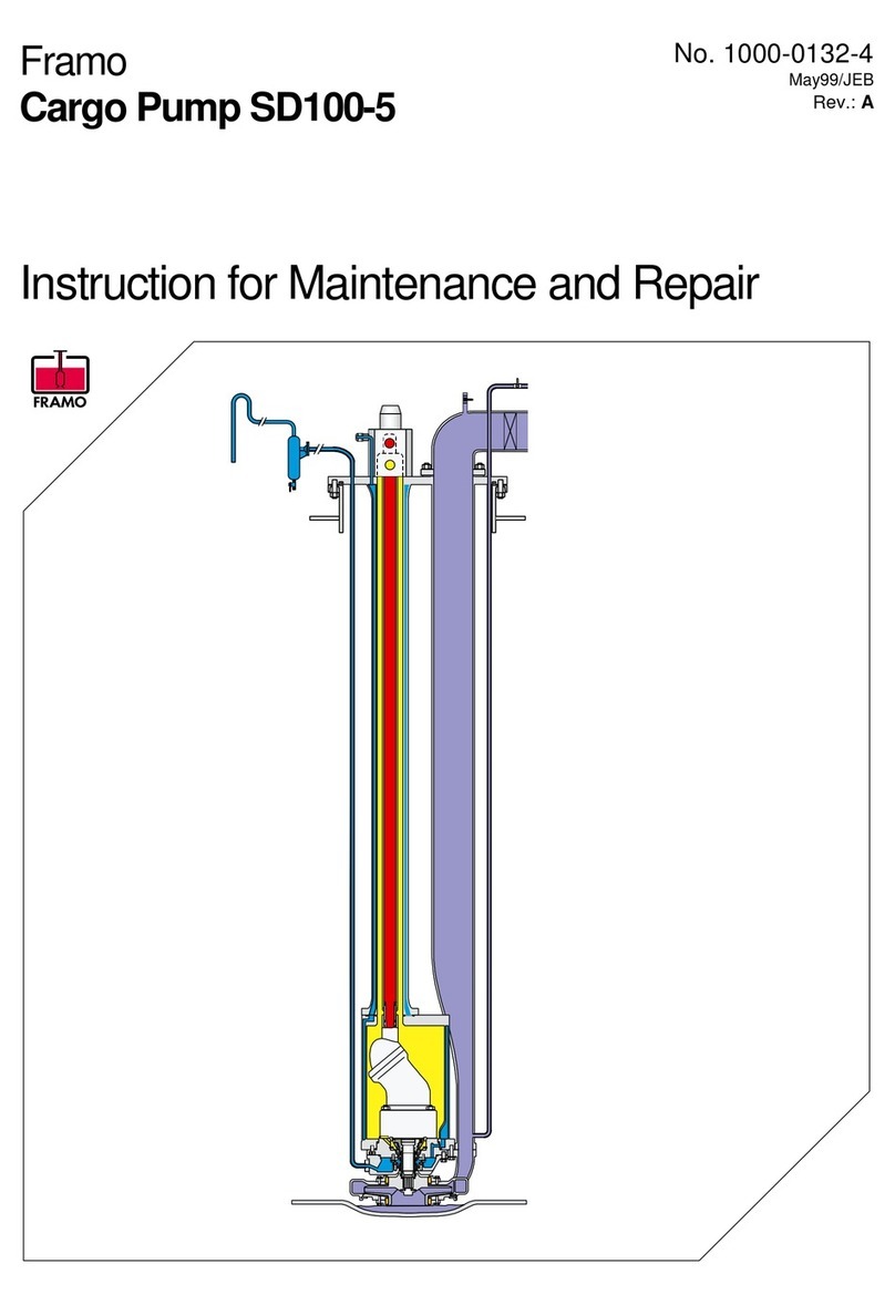
Framo SD125-5 Instructions for use

No.1000-0131-4
Rev.B22Feb06/JEB
Framo
Cargo PumpsSD125-5/SD150-5
Instruction forMaintenanceandRepair

FramoCargoPumpSD125-5/ SD150-5
INSTRUCTIONFOR MAINTENANCEAND REPAIR
No.
Date/sign.:
Page:
Rev.B:
1000-0131-4
Jan99/AGAa
2of21
22Feb06/JEB
CONTENTS
1SECTIONALDRAWING OFPUMPUNIT...........................................................................................2
1.1TechnicaldataSD125-5................................................................................................................3
1.2TechnicaldataSD150-5................................................................................................................4
2MAINTENANCEINSTRUCTION.........................................................................................................5
2.1Dismantling of impeller/ wearrings...............................................................................................5
2.2Dismantling of lipseal arrangement..............................................................................................7
2.3Assembling aftermaintenance....................................................................................................10
3REPAIR INSTRUCTION....................................................................................................................12
3.1Dismantling of mechanical oil seal..............................................................................................12
3.2Dismantling of bearinghousing...................................................................................................15
3.3Draining ofpump.........................................................................................................................18
3.4Dismantling of hydraulicmotor....................................................................................................19
3.5Assembling sequenceafterrepair...............................................................................................20
4LEAKAGETESTOFPUMP..............................................................................................................21
Reference toassociatedinstructions:
1375-0027-4Servicemanual STC-valve
0290-0036-4Installation of mechanicaloil seal
1000-0121-4Operation manualforcargo pumps(1000-0139-4forcargo pumps forFPSO/FSO)
1SECTIONALDRAWING OFPUMPUNIT
ا¼®¿«´·½±·´
°®»--«®»
ا¼®¿«´·½±·´
®»¬«®²
ݱºº»®¼¿³
ا¼®¿«´·½³±¬±®
Þ¿´´¾»¿®·²¹
͸¿º¬
Þ¿½µ-¬±°«²·¬
α´´»®¾»¿®·²¹
Ó»½¸¿²·½¿´
±·´-»¿´
Ý¿®¹±-»¿´-»¬
É»¿®®·²¹-
ʱ´«¬»½¿-·²¹
׳°»´´»®
ݱºº»®¼¿³
½¸»½µ°·°»
Fig. 1

FramoCargoPumpSD125-5/ SD150-5
INSTRUCTIONFOR MAINTENANCEAND REPAIR
No.
Date/sign.:
Page:
Rev.B:
1000-0131-4
Jan99/AGAa
3of21
22Feb06/JEB
1.1TechnicaldataSD125-5
PUMPTYPE: SD 125-5D*-HH***-***-*
DISCHARGEFLANGECONNECTION: DN 125PN 25 DIN2634
HYDRAULIC CONNECTIONS:
PRESSURE:DN 30 PN 320 FRAMO
RETURN: DN 40PN 16 FRAMO
PILOT:DN 15PN 320 FRAMO
AIR / INERTGASCONNECTION:
FOR PURGING OFCOFFERDAM:FRAMO QUICKCOUPLING
MAX. CONSUMPTION, 10MPUMP0.3NM3
FOR PURGINGOFCARGOPIPE, PUMP:FRAMO QUICKCOUPLING
MAX. CONSUMPTION, 10MPUMP:1.0NM3
HYDRAULIC OILVOLUMEIN 10MPUMP: 44 LITRE(3L/M)
RECOMMENDED HYDRAULIC OILS: SEEFRAMOLUBRICATION CHART
DESIGN PRESSURE:
CARGO25BAR
HIGH PRESSURE, HYDRAULIC: 320BAR
RETURN PRESSURE, HYDRAULIC: 16BAR
COFFERDAM:7BAR
WEIGHTOFPUMPAND PUMPPARTS:
PUMPCOMPLETE: 10M:520KG
PUMPCASING:320 KG
PUMPHEAD COMPLETE(without motor):130 KG
BEARING HOUSING COMPLETE:62 KG
HYDR. MOTOR, max. weight: 23 KG
VOLUTECASING: 30 KG
IMPELLER: 10 KG

FramoCargoPumpSD125-5/ SD150-5
INSTRUCTIONFOR MAINTENANCEAND REPAIR
No.
Date/sign.:
Page:
Rev.B:
1000-0131-4
Jan99/AGAa
4of21
22Feb06/JEB
1.2TechnicaldataSD150-5
PUMPTYPE: SD 150-5D*-HH***-***-*
DISCHARGEFLANGECONNECTION: DN 150PN 25 DIN2634
HYDRAULIC CONNECTIONS:
PRESSURE:DN 30 PN 320 FRAMO
RETURN: DN 40PN 16 FRAMO
PILOT:DN 15PN 320 FRAMO
AIR / INERTGASCONNECTION:
FOR PURGING OFCOFFERDAM:FRAMO QUICKCOUPLING
MAX. CONSUMPTION, 10MPUMP0.3NM3
FOR PURGINGOFCARGOPIPE, PUMP:FRAMO QUICKCOUPLING
MAX. CONSUMPTION, 10MPUMP:1.5NM3
HYDRAULIC OILVOLUMEIN 10MPUMP: 44 LITRE(3L/M)
RECOMMENDED HYDRAULIC OILS: SEEFRAMOLUBRICATION CHART
DESIGN PRESSURE:
CARGO 25BAR
HIGH PRESSURE, HYDRAULIC: 320BAR
RETURNPRESSURE, HYDRAULIC: 16BAR
COFFERDAM:7BAR
WEIGHTOFPUMPAND PUMPPARTS:
PUMPCOMPLETE: 10M:580KG
PUMPCASING:350 KG
PUMPUNITCOMPLETE(without motor):140 KG
BEARING HOUSING COMPLETE:63 KG
HYDR. MOTOR, max. weight: 32 KG
VOLUTECASING: 40 KG
IMPELLER: 10 KG

FramoCargoPumpSD125-5/ SD150-5
INSTRUCTIONFOR MAINTENANCEAND REPAIR
No.
Date/sign.:
Page:
Rev.B:
1000-0131-4
Jan99/AGAa
5of21
22Feb06/JEB
Ô·º¬·²¹¾±´¬-
Ù«·¼·²¹°·²
λ¼«½·²¹°´¿¬»-
Þ±´¬º±®
·³°»´´»®¸«¾
ʱ´«¬»½¿-·²¹
Ы³°«²·¬
É»·¹¸¬½¿ò
ìëµ¹
Ý¿®¹±´»¹
Í´·¼»¬±±´
Fig. 3
2MAINTENANCE INSTRUCTION
2.1Dismantling ofimpeller/ wearrings
Standard toolsSpecial tool
NameName
Allenkey10mmThreadedbolt M12 x250
Spanner13mmHexagonnut M12, 2pcs
Spanner16mmWasher12,2pcs.
Spanner18mm
Spanner24mm
Plastichammer
Slidetool
Antirotatingtoolforimpellerhub(forassembling)
Torquewrench
Loosen thebottomsupport.
Lift and securethe support topipe stack.
Removereducing plates.
Loosen bolts forimpellerhub two
turns. Knock carefullyon (orpress
down)all bolts. When impelleris
looseremoveall bolts. Removebolts
between volutecasing and cargo leg.
Replaceone bolt between volute
casing and pumpunit diagonal on
eachside of the pumpwithlifting
bolts(M12x250). Removeremaining
bolts between volutecasing and
pumpunit.
Lowervolutecasing, suction cover,
impellerand wearring inone piece.
Beforedoingservice onpumpreadtheOperationManual forCargo Pumps, Chapter3,
Maintenance information.
Fig. 2

FramoCargoPumpSD125-5/ SD150-5
INSTRUCTIONFOR MAINTENANCEAND REPAIR
No.
Date/sign.:
Page:
Rev.B:
1000-0131-4
Jan99/AGAa
6of21
22Feb06/JEB
Toavoiddamage on suction well
coating, volutecasing must be placed
upon slide tool. Slide/lift volutecasing
togetherwithimpellerand suction cover
out of well (fig. 4).Wearrings can now
be replaced. Suction coverand impeller
can now be dismantled fromthevolute
casing.
Exploded viewof wearrings/impeller/volutecasing.
Ø»¨¿¹±²¾±´¬©·¬¸©¿-¸»®
˰°»®©»¿®®·²¹-«°°±®¬
É»¿®®·²¹
ʱ´«¬»½¿-·²¹
Ú®¿³±-»¿´»´»³»²¬
Ñó®·²¹
׳°»´´»®
Í«½¬·±²½±ª»®©·¬¸-¬«¼¾±´¬-
Ô±½µ·²¹®·²¹
É»¿®®·²¹
Í«½¬·±²º«²²»´
Ø»¨¿¹±²²«¬©·¬¸©¿-¸»®
Ø»¨¿¹±²¾±´¬©·¬¸´±½µ·²¹©¿-¸»®
Ô±½µ·²¹¾®¿½µ»¬
λ¼«½·²¹°´¿¬»-ø¬©±¸¿´ª»-÷
Fig.5
λ¼«½·²¹°´¿¬»-
衡Ȩ
©»¿®®·²¹-«°°±®¬
É»¿®®·²¹
Fig.4

FramoCargoPumpSD125-5/ SD150-5
INSTRUCTIONFOR MAINTENANCEAND REPAIR
No.
Date/sign.:
Page:
Rev.B:
1000-0131-4
Jan99/AGAa
7of21
22Feb06/JEB
2.2Dismantling oflipsealarrangement
StandardtoolsSpecialtools
NameName
Allen key6mm Extractorforimpellerhub
Allen key10 mmAssemblingcylinder
Spanner10mm
Spanner13mm
Spanner18mm
Spanner24mm
SnapringplierA2
Note! If the pumphas liquidfilled cofferdam, drainthe cofferdamas informed in
Operationmanual beforefurtherdismantling.
Loosen lock washerandremoveimpellerhub bolt. Impellerhub ispulled off by usingextractor.
Beverycareful not todamageo-ringsandceramicsleeve.
Dismantlelowerpart of cofferdamcheck pipe.
Û¨¬®¿½¬±®
Fig. 6

FramoCargoPumpSD125-5/ SD150-5
INSTRUCTIONFOR MAINTENANCEAND REPAIR
No.
Date/sign.:
Page:
Rev.B:
1000-0131-4
Jan99/AGAa
8of21
22Feb06/JEB
Install assemblingcylindertokeep ceramic sleeveinplace. See fig. 7.
Removeseal ring housing. Usebolts forsealring housing as extractorbolts if necessary.
Í»¿´®·²¹¸±«-·²¹
©·¬¸½±²²»½¬·±²¬±
½±ºº»®¼¿³½¸»½µ°·°»
ß--»³¾´·²¹½§´·²¼»®
Í»²-·¬·ª»´·°-
ÒÞÿÙ®±±ª»
Fig. 7
Dismantlesupport rings and single/ doublelipseal. Singleand doublelipseal is called Framoseal set.
Check and clean ceramic sleeve. Change Framoseal set if necessary.
Note! Theceramicsleevemust be handled very carefully as it is very brittleand may crack if
dropped.

FramoCargoPumpSD125-5/ SD150-5
INSTRUCTIONFOR MAINTENANCEAND REPAIR
No.
Date/sign.:
Page:
Rev.B:
1000-0131-4
Jan99/AGAa
9of21
22Feb06/JEB
Exploded view of lipsealarrangement.
Fig.8
Singlelipseal
Support ring
Hexagonbolt
Support ring
Doublelipseal
O-ring
Seal ring housing
Hexagonbolt
Drive ring
Framoseal element
O-ring
Bolt
Lowerpart of
cofferdampipe
Seal ring
Bolt
Impeller hub
Washer
Bolt with
lockingwasher
Ceramicsleeve
Bracket
Seal ring
Replace
lockingwasher
ateveryservice.
Plasticring,
tobereplaced
ateveryservice.
Nut

FramoCargoPumpSD125-5/ SD150-5
INSTRUCTIONFOR MAINTENANCEAND REPAIR
No.
Date/sign.:
Page:
Rev.B:
1000-0131-4
Jan99/AGAa
10of21
22Feb06/JEB
2.3Assembling aftermaintenance
CHECKALL SEALELEMENTS, BACK-UPRINGS, SEALELEMENTGROOVES AND
SEALFACES. PAYSPECIALATTENTION TO THETEFLON RINGSAND BE
ABSOLUTESUREOFNO DEFORMATION NOR RADIALGROOVES.
NEVER INSTALL DAMAGED SEALRINGS. CHECKSEALFACES ON PUMPAND BE
SUREOFNO CORROSION, CRACKS,DIRTETC.
-USE ONLYGENUINESPAREPARTS-
ALL SCREWSAND NUTSHAVE TO BE ASSEMBLED WITH SPECIFIED TORQUE.
IFNOTORQUEISSPECIFIED,USE THEFOLLOWING TORQUE:
ACID RESISTANTBOLTSAND NUTS,QUALITYA4-80
M6M8M10 M12 M16 M20
9Nm22Nm45 Nm80 Nm190 Nm370 Nm
All bolts and nutsaretobe fastened using atorque wrench.
Acidresistant bolts must be partly coated withathin
layerof "molybdenumdisulphide"(Molykote)priorto
assembling. Apply asmall amount tothe lowerpart of
the threads, seefig. 9.
Allassembling has tobedoneinreversedway according tothedismantlingsequence.
PAYSPECIALATTENTION TO THEFOLLOWING POINTS:
Lipseal arrangement
Useassembling cylindertofix the ceramic sleeveintocorrect position. Donot removethe cylinder
beforeall Framoshaft seals has been installed. When assembling lipseals be surethat support
ring is tightened up until metallic contact. This toavoidscrews toloosen. The doublelipsealshall
be mounted as showninfig. 7, chapter2.2.
Note! The ceramic sleevemust be handled very carefullyas it is very brittleand may
crack if dropped.
ImpellerHub
Priortomounting of impellerhub, apply
athinlayerof MolykoteTP-42 tothe
shaft spline and shaft steering as shown
infig. 10.
Check that the drivering is incorrect
position at the end of the ceramic
sleeve.
When assembling impellerhub, be
careful not todamage seal rings.
Besuretolock the impellerhub bolt
properly. Lockingwashermust be
replaced. Check the shaft alignment
according tofig. 10.
0.05
DriveRing
Securingring
Lockingwasher
Hub
Lowerpartof
shaftspline
Hub
0.04
0.04
Priortomounting
applyathinlayer
of MolykoteTP-42
at theselocations
Fig.10
ß°°´·½¿¬·±²
¿®»¿
Fig. 9

FramoCargoPumpSD125-5/ SD150-5
INSTRUCTIONFOR MAINTENANCEAND REPAIR
No.
Date/sign.:
Page:
Rev.B:
1000-0131-4
Jan99/AGAa
11of21
22Feb06/JEB
WearRings
When mounting new wearrings be surethat support ring is tightenuntilmetallic contact.
Impeller
Toensureoptimal friction between impellerhub and impellerthe contacting surfaces havetobe
clean and dry (free fromgrease)beforeassembling.
Volutecasing withimpeller
Slide volutecasing and impellerintosuction well. Framosealelement istobe placed on top of
impellerwhen volutecasing is inposition below impellerhub. Check position of the guiding pinin
flange connection between pumpunit and volutecasing(see fig. 3).
Lift the completeunit with2lifting bolts M12x250 until theseboltscanbe replaced withthe original
bolts. Assemblethe bolts forimpellerhub andvolutecasing. Tighten all bolts evenlybyusing the
torquewrench. Toavoidrotationof impellerhub usethe antirotating tool.
Ù«·¼·²¹°·²
Ô·º¬·²¹¾±´¬-
Þ±´¬º±®·³°»´´»®¸«¾
Í»¿´®·²¹-
ß²¬·®±¬¿¬·²¹¬±±´
Í´·¼»¬±±´
Fig.11
Reducing plates
Replacethe reducing plates beforefastening upperwearring support (see fig. 3and4).
Bottomsupport (arrangement withcounternut)
Tighten nuts as follows (fig. 12):
1)Assembleuppernut, use190 Nmtorque.
2)Tighten all bolts one moretime,
use190 Nmtorque.
3)Assemblelowernut, use190 Nmtorque.
Í«°°±®¬®·²¹
Ú¿-¬»²»®-
Ó¿¬»®·¿´
Ï«¿´·¬§
æÍ¬¿·²´»--
æßìóèð
Í«°°±®¬¾®¿½µ»¬
˰°»®²«¬øÌ±®¯«»ïçðÒ³÷
Ú´¿¬©¿-¸»®
ݱ¿¬·²¹¬±«½¸«°
Ú´¿¬©¿-¸»®
Ô±©»®²«¬øÌ±®¯«»ïçðÒ³÷
Fig. 12

FramoCargoPumpSD125-5/ SD150-5
INSTRUCTIONFOR MAINTENANCEAND REPAIR
No.
Date/sign.:
Page:
Rev.B:
1000-0131-4
Jan99/AGAa
12of21
22Feb06/JEB
3REPAIR INSTRUCTION
3.1Dismantling ofmechanicaloilseal
StandardtoolsSpecialtools
NameName
Allenkey6mm Extractorforimpeller
Extractorforsleeve
(tobe used withextractorforimpeller)
Assembling cylinder
(forprotection)
Assembling tool(formech. oilseal)
Allenkey10mm
Spanner18mm
Spanner19mm
Snapring plierA2
Threadedbolt M12x250, 2pcs
Hexagonnut M12, 2pcs
Washer12,2pcs
Removethebearing housing fromthe pumpcasing. Useextractorbolts M12.
Û¨¬®¿½¬±®¾±´¬-
ß--»³¾´·²¹½§´·²¼»®
º±®°®±¬»½¬·±²
Fig.12

FramoCargoPumpSD125-5/ SD150-5
INSTRUCTIONFOR MAINTENANCEAND REPAIR
No.
Date/sign.:
Page:
Rev.B:
1000-0131-4
Jan99/AGAa
13of21
22Feb06/JEB
Removeupperseal ring housing.
Removestationary part ofmechanical seal.
˰°»®-»¿´®·²¹
¸±«-·²¹
Ó»½¸¿²·½¿´-»¿´
-¬¿¬·±²¿®§°¿®¬
Fig. 13
Pull out rotating part of mechanical seal by useof assembling tool.
ß--»³¾´·²¹¬±±´º±®
³»½¸¿²·½¿´-»¿´
Fig. 14

FramoCargoPumpSD125-5/ SD150-5
INSTRUCTIONFOR MAINTENANCEAND REPAIR
No.
Date/sign.:
Page:
Rev.B:
1000-0131-4
Jan99/AGAa
14of21
22Feb06/JEB
Explodedview of mechanicaloil seal.
Þ±´¬
˰°»®-»¿´®·²¹¸±«-·²¹
Ú®¿³±-»¿´»´»³»²¬
Í´»»ª»º±®³»½¸ò±·´-»¿´
ͬ¿¬·±²¿®§°¿®¬
Ó»½¸¿²·½¿´
±·´-»¿´
ન¬·²¹°¿®¬
Fig.15

FramoCargoPumpSD125-5/ SD150-5
INSTRUCTIONFOR MAINTENANCEAND REPAIR
No.
Date/sign.:
Page:
Rev.B:
1000-0131-4
Jan99/AGAa
15of21
22Feb06/JEB
3.2Dismantlingofbearing housing
StandardtoolsSpecialtools
NameName
SnapRingPlierJ4Extractorforimpellerhub
SnapRingPlierA3Extractorforsleeve
(tobe used withextractorforimpellerhub)
Pull out the shaft,ball-bearing, rotating part of back-stop unit, and rollerbearing as aunit.
Fig. 16
If the back-stop unit orthe cylindrical rollerbearing is tobe replaced, always change bothrotating
and stationary parts.

FramoCargoPumpSD125-5/ SD150-5
INSTRUCTIONFOR MAINTENANCEAND REPAIR
No.
Date/sign.:
Page:
Rev.B:
1000-0131-4
Jan99/AGAa
16of21
22Feb06/JEB
Removeif necessary shaft sleeveformechanical oil seal by useof extractor.
Û¨¬®¿½¬±®º±®
-¸¿º¬-´»»ª»
Fig. 17
Replaceif necessary the completemechanicalseal, andshaft sleeve. The shaft sleevemust be
heatedtoapproximately 120!C priortoassembling.See instruction 0290-0036-4forinstallation of
mechanical oilseal.

FramoCargoPumpSD125-5/ SD150-5
INSTRUCTIONFOR MAINTENANCEAND REPAIR
No.
Date/sign.:
Page:
Rev.B:
1000-0131-4
Jan99/AGAa
17of21
22Feb06/JEB
Exploded view of bearings.
Ý·®½´·°-
͸¿º¬
Þ¿´´¾»¿®·²¹
Ý·®½´·°-
Þ¿½µ-¬±°«²·¬
α´´»®¾»¿®·²¹
Ý·®½´·°-
Í´»»ª»º±®³»½¸ò-»¿´
©·¬¸Ñó®·²¹-
Þ»¿®·²¹¸±«-·²¹
Í»¿´®·²¹
Í»¿´®·²¹
ݱª»®
Fig.18

FramoCargoPumpSD125-5/ SD150-5
INSTRUCTIONFOR MAINTENANCEAND REPAIR
No.
Date/sign.:
Page:
Rev.B:
1000-0131-4
Jan99/AGAa
18of21
22Feb06/JEB
3.3Draining ofpump
Beforestarting dismantling of hydraulic motor, check that hydraulic pressureinlet valveand valve
on pilot line areclosed. Open local control valve.
Releaseall pressurechambers by using the bleedplugs intheSTC-valveand non returnvalve.
StandardtoolsSpecialtools
NameName
DrainpumpDrain tool
ß·®½±²²»½¬·±²
Ü®¿·²°«³°
Ü®¿·²¬±±´
̱-¬±®¿¹»¬¿²µ
Fig. 19

FramoCargoPumpSD125-5/ SD150-5
INSTRUCTIONFOR MAINTENANCEAND REPAIR
No.
Date/sign.:
Page:
Rev.B:
1000-0131-4
Jan99/AGAa
19of21
22Feb06/JEB
3.4Dismantling ofhydraulicmotor
StandardtoolsSpecialtools
NameName
Allen key10mmExtractorforloosen hydr.motor
Spanner17mmJack
Spanner18mm
Spanner19mm
Spanner24mm
Snapringplier
Volutecasingand bearing housinghavetobe removed.
Drainthe pump’s hydraulic section (ref. section 3.3).
Install the jack . Removecirclips. If necessaryuseextractortoloosen the hydraulicmotorfromthe
high pressurepipe. Lowerthe hydraulic motorby using the jack.
Ö¿½µ
Û¨¬®¿½¬±®
Ý·®½´·°-
Fig. 20

FramoCargoPumpSD125-5/ SD150-5
INSTRUCTIONFOR MAINTENANCEAND REPAIR
No.
Date/sign.:
Page:
Rev.B:
1000-0131-4
Jan99/AGAa
20of21
22Feb06/JEB
3.5Assembling sequence afterrepair
Hydraulic motor
If anew hydraulic motoris installed:
-check that bothplugs at T-ports areremoved
-check that the shaft seal is removed.
É·¬¸±«¬-¸¿º¬-»¿´ Ú»»´»®
É·¬¸±«¬°´«¹-¿¬Ìó°±®¬-
Fig. 21
Check position of hydraulic motorand motorflange according toassemblydrawing.
Check that circlips forassemblingmotorincoveris incorrect position (ref. fig.20).
Back Stop Unit
Check direction of back stop unit.
(Counterclockwise, seen fromthreaded endof the shaft.)
Ball bearing
Ball mountingslot pointing downwardsagainst theback stopunit whenmounting ball bearing.
When installing shaftintobearing housing, rotatethe shaft foreasy enteringof rotating part
of back stop unit.
Mechanical Oil Seal
Assemblemechanical sealaccording toinstruction290-36-4E.
Clean seal faces withclean ragswetted withdenaturated alcohol.
This manual suits for next models
1
Table of contents
Other Framo Water Pump manuals