Franklin Fueling Systems Healy 8701VV User manual

6-1
CARB Approved IOM 6 - Healy Breakaway Model 8701VV - Executive Orders VR-201 and VR-202
Healy Model 8701VV Breakaway
35 to 70 foot pounds. Be sure the vapor tube fitting slides easily into
item 2 before final tightening.
install the secondary hose and tighten to 35 to 70 foot pounds. Be sure
the vapor tube fitting slides easily into item 3 before final tightening.

6-2
CARB Approved IOM 6 - Healy Breakaway Model 8701VV - Executive Orders VR-201 and VR-202
I. HEALY BREAKAWAY RECONNECTION CLAMP
TOOLS NEEDED:
• Healy Breakaway Reconnection Clamp, Part No. 795
• 8mm Hex Head Socket
• Torque wrench
• Safety glasses
RECONNECTION PROCEDURE
1. Inspect each half of the separated breakaway for obvious damage to the outer-shell, plastic
inserts or o-rings; including cracks, chips or tears that may effect reconnecting the two halves.
2. Check the shear pin bushing hole (see Figure 2) located in the top half of the breakaway
for any part of the pin left behind at separation. A gentle tap on the opposite side of the
breakaway should eject the pin.
3. After completing inspection, lightly lubricate the main o-ring on the top half of the breakaway.
Any weight motor oil is acceptable.
4. Slide the top clamp of the Breakaway Reconnection Clamp onto the two at surfaces on the
top half of the breakaway (See Figure 1) installed on the dispenser (attached to whip hose).
5. Slide the separated bottom half of the breakaway (with hose and nozzle attached) onto the
bottom clamp of the Breakaway Reconnection Clamp and begin squeezing the grip to slowly
bring the two halves together. Check the main o-ring for position as the top and bottom of the
breakaway come together.
6. Align the dowel pin in the bottom half of the breakaway with the dowel pin guide located in the
DRIVE-OFF BREAKAWAY RECONNECTION PROCEDURE
Use this procedure to either reconnect or disconnect (reverse order) the Healy 8701VV Breakaway as
part of Section 1.4 Procedure for Reconnecting Breakaway and Testing Fueling Point after Drive-Off
in the Assist Systems Scheduled Maintenance.
NOTE: Breakaway Reconnections must be logged in the GDF Maintenance Log.
Reconnection Procedure Option
I. HEALY BREAKAWAY RECONNECTION CLAMP .......................................................................... 1
II. EASYGRIP RECONNECTION TOOL ............................................................................................. 3

6-3
CARB Approved IOM 6 - Healy Breakaway Model 8701VV - Executive Orders VR-201 and VR-202
top half of the breakaway. When dowel pin and guide are aligned, continue squeezing tool grip
until the breakaway halves join together.
CAUTION: Reconnection can cause a small amount of gasoline to leak out of the
breakaway. A towel wrapped loosely around the breakaway can help to
minimize fuel spills.
7. Remove the shear pin (#787) located in the spare shear pin location of the breakaway and
install in place of the original.
8. Torque the shear pin to 20 inch-pounds (~ 1.5 ft-lbs). DO NOT OVER-TIGHTEN.
9. If available, install a shear pin (#787) in the spare shear pin location.
10. Remove the Breakaway Reconnection Clamp.
11. Proceed with the tests outlined in Section 1.4 of the Healy Systems Scheduled Maintenance.
Figure 1 Figure 2
Top Clamp
Bottom Clamp
Tool Grip
Dowel Pin
Dowel Guide
Shear Pin Bushing Hole
Shear Pin Installation
Spare Shear
Pin
Franklin Fueling Systems Website: http://www.franklinfueling.com
3760 Marsh Road Email: [email protected]
Madison, Wisconsin 53718 USA Telephone: 800-225-9787
ARB Approved Installation, Operation and Maintenance Manual Fax: 608-838-6433

6-4
CARB Approved IOM 6 - Healy Breakaway Model 8701VV - Executive Orders VR-201 and VR-202
II. EASYGRIP BREAKAWAY RECONNECTION CLAMP
TOOLS NEEDED:
• EasyGrip Reconnection Clamp
• 8 mm Hex Head Socket
• Torque wrench
• Safety Glasses
RECONNECTION PROCEDURE
NOTE: Additional information on the EasyGrip operation can be found by viewing a video clip on
their website at http://www.simplegrip123.com/
1. Inspect each half of the separated breakaway for obvious damage to the outer-shell, plastic
inserts or o-rings; including cracks, chips or tears that may effect reconnecting the two halves.
2. Check the shear pin bushing hole, (See Figure 1) located in the top half of the breakaway for
any part of the pin left behind at separation. A gentle tap on the opposite side of the breakaway
should eject the pin.
Figure 1

6-5
CARB Approved IOM 6 - Healy Breakaway Model 8701VV - Executive Orders VR-201 and VR-202
3. After completing inspection, lightly lubricate the main o-ring on the top half of the breakaway
(See Figure 1). Any weight motor oil is acceptable.
4. With the EasyGrip in its full open position, place the top portion of the breakaway into the top
side of the EasyGrip and the bottom portion of the breakway into the bottom side (See Figure 2).
Figure 2
5. Pull the two handles of the Easy Grip down at the same rate to slowly bring the two halves
together. Check the main o-ring for position as the top and bottom of the breakaway come
together. See Figure 3.
Figure 3

6-6
CARB Approved IOM 6 - Healy Breakaway Model 8701VV - Executive Orders VR-201 and VR-202
6. Align the dowel pin in the bottom half of the breakaway with the dowel pin guide located in the
top half of the breakaway. When the dowel pin and guide are aligned, continue squeezing tool
grips until the breakaway halves come together. See Figure 4
Figure 4
CAUTION: Reconnection can cause a small amount of gasoline to leak out of the breakaway.
A towel placed in front of the reconnection zone of the breakaway can help to
minimize fuel spills.
7. Remove the shear pin (#787) located in the spare shear pin location of the breakaway and install
in place of the original. See Figure 5
Figure 5

6-7
CARB Approved IOM 6 - Healy Breakaway Model 8701VV - Executive Orders VR-201 and VR-202
8. Torque the shear pin to 20 inch-pounds (~ 1.5 ft-lbs).
DO NOT OVER-TIGHTEN
9. If available, install a shear pin (#787) in the spare shear pin location.
10. Remove the Easygrip.
11. Proceed with the tests outlined in Section 1.4 of the Healy Systems Scheduled Maintenance.

6-1
CARB Approved IOM 6 - Healy Breakaway Model 807 Swivel - Executive Orders VR-201 and VR-202
Healy Model 807 Swivel Breakaway
hose. Tighten to 35 to 70 foot pounds. Be sure the valve and spring
(items 6 & 11) are in place before final tightening.
35 to 70 foot pounds. Be sure the vapor tube fitting slides easily into
the nozzle before final tightening.

6-2
CARB Approved IOM 6 - Healy Breakaway Model 807 Swivel - Executive Orders VR-201 and VR-202
DRIVE-OFF BREAKAWAY RECONNECTION PROCEDURE
Use this procedure to either reconnect or disconnect (reverse order) the Healy 807 Swivel Breakaway
as part of Section 1.4 Procedure for Reconnecting Breakaway and Testing Fueling Point after Drive-
Off in the Healy Systems Scheduled Maintenance.
TOOLS NEEDED:
•Healy Breakaway Reconnection Clamp, Part No. 795
•8mm Hex Head Socket
•Torque wrench
•Safety glasses
1. Inspect each half of the separated breakaway for obvious damage to the outer-shell, plastic
insert or o-rings; including cracks, chips or tears that may effect reconnecting the two halves.
2. Check the shear pin bushing hole (see Figure 3) located in the half of the breakaway attached
to the hose for any part of the pin left behind at separation. A gentle tap on the opposite side
of the breakaway should eject the pin.
3. After completing inspection, lightly lubricate the main o-ring on the half of the breakaway that’s
attached to the hose and the two small o-rings inside the half of the breakaway attached to the
nozzle. Any weight motor oil is acceptable.
4. Remove the black handle cover from the nozzle (See Figure 1).
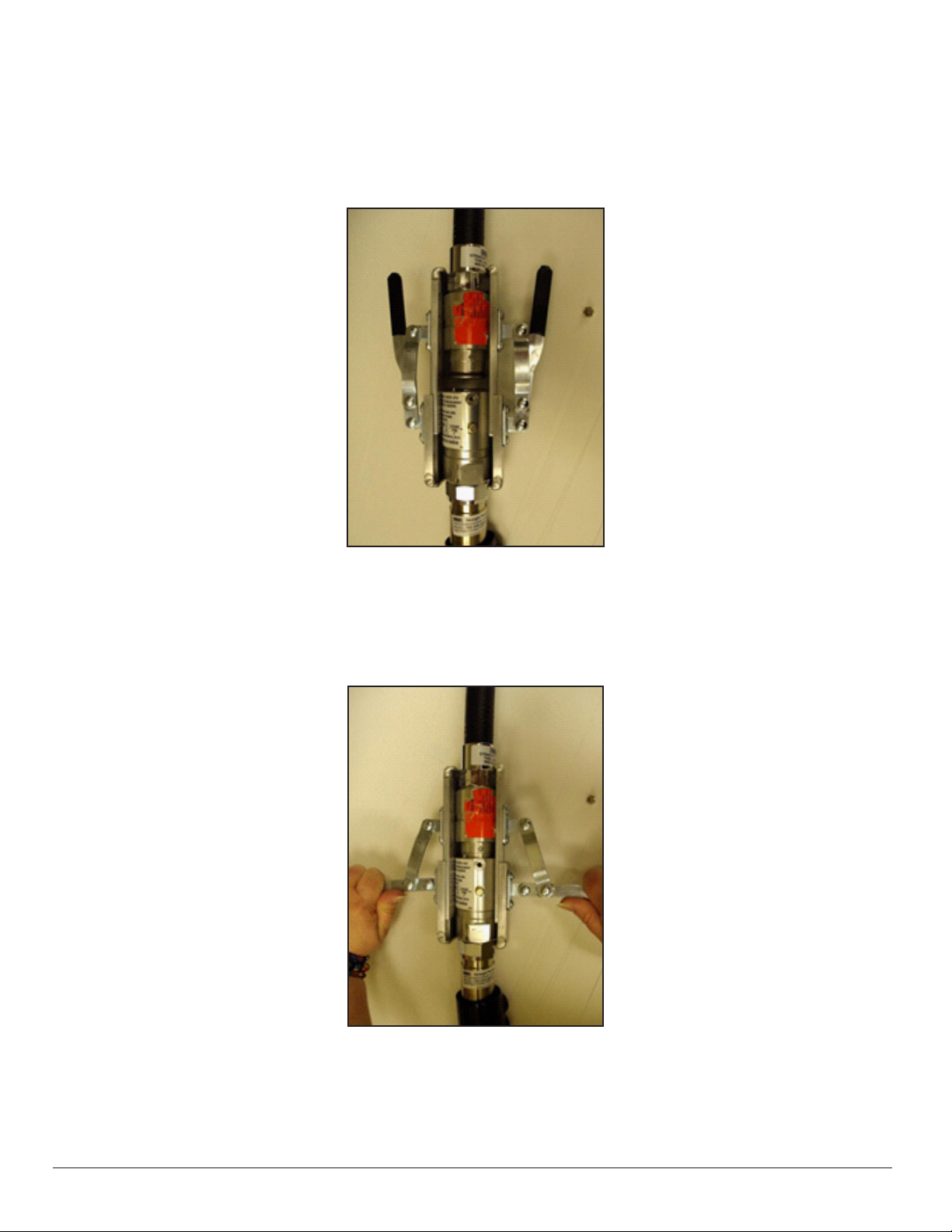
5. Slide the top clamp of the Breakaway Reconnection Clamp above the two at surfaces on the
nozzle (See Figure 2).
6. Slide the half of the breakaway that’s attached to the hose onto the bottom clamp of the
Breakaway Reconnection Clamp and begin squeezing the grip to slowly bring the two halves
together. Check the main o-ring for position as the top and bottom of the breakaway join
together (See Figure 2).
7. Align the dowel pin in the top half of the breakaway with the dowel pin guide located in the
bottom half of the breakaway (See Figure 3). When dowel pin and guide are aligned, continue
squeezing tool grip until the breakaway halves come together (See Figure 4).
Caution: Reconnection can cause a small amount of gasoline to leak out of the
breakaway. A towel wrapped loosely around the breakaway can help to
minimize fuel spills.

6-3
CARB Approved IOM 6 - Healy Breakaway Model 807 Swivel - Executive Orders VR-201 and VR-202
7. Remove the shear pin (#787-1) located in the spare shear pin location of the breakaway and
install in place of the original.
8. Torque the shear pin to 20 inch-pounds (~ 1.5 ft-lbs). DO NOT OVER-TIGHTEN.
9. If available, install a shear pin (#787-1) in the spare shear pin location.
10. Remove the Breakaway Reconnection Clamp.
11. Proceed with the tests outlined in Section 1.4 of the Healy Systems Scheduled Maintenance.
Figure 1 Figure 2
Bottom Clamp
Tool Grip
Top Clamp
Figure 3 Figure 4
Dowel Pin
Dowel Guide
Shear Pin Bushing Hole
Shear Pin Installation
Spare Shear
Pin

6-4
CARB Approved IOM 6 - Healy Breakaway Model 807 Swivel - Executive Orders VR-201 and VR-202
Franklin Fueling Systems Website: http://www.franklinfueling.com
3760 Marsh Road Email: [email protected]
Madison, Wisconsin 53718 USA Telephone: 800-225-9787
ARB Approved Installation, Operation and Maintenance Manual Fax: 608-838-6433

PAGE 1 OF 4
2750 US RT 40
TIPP CITY, OHIO 45371 USA
WWW.CATLOW.COM
©2016 Veeder-Root LLC. All Rights Reserved.
Phone (800) 222-8569 Fax (937) 898-8631
ver
DISPENSER
TOP VIEW
VERY IMPORTANT
READ THIS BEFORE INSTALLING YOUR BREAKAWAY
WARNING: USE ONLY ON SYSTEMS RATED AT 50 PSI MAXIMUM
USE ON SYSTEMS HAVING HIGHER STATIC PRESSURE MAY CAUSE PEMATURE SEPARATION
ALWAYS CHECK FOR ELECTRICAL CONTINUITY FOLLOWING PETROLEUM EQUIPMENT INSTITUTE
(PEI) RECOMMENDED TEST PROCEDURE (PEI/RP400-02)
PRIOR TO INSTALLATION: Refer to the model of breakaway for the maximum pull force before you proceed with the instructions
Caution must be used when testing to prevent damage to the dispenser or personal injury.
ALL DISPENSERS MUST BE BOLTED TO THE ISLAND. (NFPA 30A 6.3.4 and PEI/RP500-11 2.2)
CONFIRM DISPENSER IS SECURE.
-Attach a spring scale to the dispenser where the breakaway willbe installed. 2
-Apply a 350 lbs pull force at various angles and check theemergency valves, 65
Dispenser and hose assembly. (UL STANDARD 567)
-Release the load and complete the installation ofthe breakaway. 1
CTMCA INSTALLATION KIT - P/N 4037
4
3
INSTALLATIONNOTES
-The CATLOW in-line breakaway must always be installed between two hose sections (example: whip & main hose)
-On side hose connections install the breakaway between the nozzle and the hose retractor (NFPA 30A 6.5.3)
DO NOT INSTALL THE BREAKAWAY ON THE DISPENSER SIDE OF THE HOSE RETRACTOR
-On an overhead hose connection, install the short section of whip hose then the breakaway, hose and nozzle
NOTE: Catlow recommends using a swivel end hose in proximity to the CAM TWIST
1.
Isolate/turn the dispenser OFF and relieve the line pressure from the system by opening the nozzle and allowing the system to drain into
an approved metalcontainer.
2.
Observe the flow direction arrow on the breakaway and install with the flow arrows pointing toward the nozzle.
3.
Use thread sealant recommended by UL for petroleum products on pipe thread connections.
4.
Use oil or grease on straight or metric thread o-ring fittings - DO NOT USE TEFLON TAPE.
5.
When replacing the CTMCAs with M3418 adapters on both ends, there are special precautions that must be observed. When replacing
CTMCA, ensure the M3418 ferrule stays with each hose and does not get discarded along with the discarded CTMCA.
Whip Hose
Ferrule
M3418 Adapter M3418Adapter
Ferrule
Nozzle Hose
Breakaway Co
4736
6.
Re-attach the hose to the M3418 adapter and tighten to 50 ft-lbs torque. CAUTION: Torque adjacent parts only (e.g., hose and
adapter to which it connects). Slide plastic cover 4736 over the breakway as far as it will go (for retrofit instructions see page2).
7.
Activate/turn the dispenser ON and purge the hoses and nozzles of air into an approved metalcontainer.
8.
Check the system for leaks, replace any item that exhibits signs of leakage.
UseOnlyULListed
PasteTypeThread
Sealant
Hosesshouldnotbelongenoughthatavehiclecould
driveoverthehoseresultinginadirectpullonthe
retractor cableor dispenser and bypass the breakaway
AlwaysReferToYour
LocalCity,StateOrFederal
Testing Regulations
Recommended Instructions
Installation, Maintenance, Inspection
CATLOW CTMCA Breakaway 577014-071
DATE 03/2016
INSTALLATION INSTRUCTIONS FOR THE CTMCA BREAKAWAY
CAM
TWIST
CTMCA
Qty.
P/N
Description
1ea.
2ea.
CTMCA
M3418
Cam Twist Magnetic Breakaway
CTMCA Hose Adapter

Phone (800) 222-8569 Fax (937) 898-8631
TIPP CITY, OHIO 45371 USA
©2016 Veeder-Root LLC. All Rights Reserved.
1. Isolate/turn off dispenser, relieve line pressure from the whip hose and the nozzle hose. Drain fuel into an approved metal
container.
2. Inspect the entire system for damage and/or leaks. Replace any damaged components in the system (PEI/RP500-119.2.2).
3. Clean the magnet surfaces on both the male and female couplings and inspect fordamage.
4. Replace damaged o-rings using CATLOW repair kit.
Lubricate the o-rings and the mating male and female surfaces with oil or grease.
4a On Model CTMCA, O-rings must be replaced using CATLOW repair kit P.N.#2977.
5. Align the flow arrows and push the halves together engaging the coupling mechanism until a noticeable snap is felt and the
etched guide mark above the letters CTMCA on the nozzle half of the breakaway is not visible (see illustrations on page 3).
6. Test the reconnection by pulling on the hose just below the breakaway.
7. Activate/turn on the dispenser and purge the hose and nozzle of air into an approved metalcontainer.
8. With the system pressurized, check for leaks around the breakaway, nozzle, both hoses and alljoints.
9. Replace any item that exhibit signs of leakage.
1. Disassemble the whip hose from the breakaway (see Figure 1 below). NOTE: After disconnecting the whip hose from a
CTMCA with M3418 adapters, ensure the ferrule does not get discarded (if it should come out of thebreakaway
when the hose is disconnected). Refer to the illustration in Step 5 of the INSTALLATION INSTRUCTIONS FOR THE
CTMCA BREAKAWAY on page 1.
2. Slide breakaway cover 4736 onto the whip hose ( see Figure 2below).
3. Re-attach the hose to the M3418 adapter and tighten to 50 ft-lbs torque ( see Figure 3 below). CAUTION: Torque adjacent
parts only (e.g., hose and adapter to which itconnects).
4. Slide down the cover onto the breakaway as far as it will go (see Figure 4below).
Figure 1.
Figure 2.
Figure 3.
Figure 4.
Whip Hose M3418 Adapter M3418Adapter
Whip hose
M3418 Adapter M3418Adapter
PAGE 2 OF 4
2750 US RT 40
WWW.CATLOW.COM
Recommended Instructions 577014-071
DATE 03/2016
CAM TWIST MAGNETIC BREAKAWAY
Model: CTMCA
IF SEPARATION OCCURS
RETROFITTING PLASTIC COVER 4736 ONTO BREAKWAY
Breakaway cover 4736
CAM
TWIST
CAM TWIST
CAM
TWIST
CTMCA
CTMCA
CTMCA
CAM
TWIST
CTMCA

PAGE 3 OF 4
2750 US RT 40
TIPP CITY, OHIO 45371
WWW.CATLOW.COM
©2016 Veeder-Root LLC. All Rights Reserved.
Phone (800) 222-8569 Fax (937) 898-8631
USA
Isolate fuel pressure/flow from the system. If dispenser is off and depressurized, o-rings can be
safely replaced WITHOUT draining the hose assembly. Always lubricate o-rings before installing and
reconnecting. An o-ring pick or small stiff wire will be useful to remove old o-rings.
SEPARATES IN ONE DIRECTION ONLY
Use two open end wrenches and
apply in a clockwise rotary torque
VAPOR VAPOR
VAPOR VAPOR
The Vapor o-ring is the smallest
o-ring in the repair kit. It is located in
the upper section of the breakaway.
This will need to be replaced if meter
creep is observed.
When the two halves
of the breakaway are
correctly connected, the
guide mark (see adjacent
Dirt and Liquid drawings to
the right) etched above the
letters CTMCA on the
nozzle half of the breakaway
will not be visible.
DIRT DIRT
DIRT DIRT
The largest o-ring is used to keep
dirt out of the nylon covers and
breakaway assembly. Replace if
missing or damaged.
LIQUID LIQUID
LIQUID LIQUID
Occasionally during a drive-off or reconnection, the liquid o-ring
gets pinched or cut. If a breakaway leaks after reconnection,
replace the liquid o-ring. Reach inside the lower section of the
breakaway, squeeze the o-ring and remove it.
REPAIR KIT
PN DESCRIPTION
2977 Repair Kit CTMCA
CATLOW products should be used in compliance with applicable federal, state and local laws and regulations. Product selection
should be based on physical specifications and limitations and compatibility with the environment and material to be handled.
577014-071
DATE 03/2016
O-Ring REPAIR KIT Instructions
CAMTWIST Magnetic Breakaway
CTMCA O-RING REPLACEMENT
The CTMCA has four (4) O-rings that can be serviced or replaced in the field. These are used to seal liquid (Qy. 2),
vapor (Qty. 1) and dirt (Qty. 1). To Replace these O-rings use CATLOW PN #2977.
ALWAYS LUBRICATE WITH OIL OR GREASE BEFORE RECONNECTION
Guide
mark
Guide
mark

PAGE 4 OF 4
2750 US RT 40
TIPP CITY, OHIO 45371
WWW.CATLOW.COM
©2016 Veeder-Root LLC. All Rights Reserved.
Phone (800) 222-8569 Fax (937) 898-8631
USA
_
_
_
EQUIPMENT WARRANTY
Veeder-Rootwarrantsthatthisproductshallbefreefromdefectsinmaterialandworkmanshipandiscompliant
with allapplicable performancestandards andspecificationsfor which it has beencertified,for aperiodof one
(1)
year from dateof installation when proof of the date of install is provided. Orfifteen (15) months from date of
manufacture(seetermsbelow) whenproofof dateof installationisnotprovided.
Date of manufacture:
*Product S/N:
*Dateofinstallation:
*Technician number:
*
Required Information
*Installation Address:
Street:
City: State:
Phone: - -
Thiscomponentwas testedatthetimeofmanufactureandmeetsalltheapplicableperformancestandardsand
specification to which it was certified: E.O. VR-201 and VR-202.
For detailed warranty terms see EO warranty exhibits (VR-201/VR-202 Exhibit 6) on the ARB Web site at:
http://www.arb.ca.gov/vapor/eo-evrphaseII.htm
577014-071
DATE 03/2016
CAMTWIST Magnetic Breakaway
Warranty

6-1
CARB Approved IOM 6 – EVR Vacuum Assist Breakaways VR-201 and VR-202 09/16
VST Installation Procedure for
Phase II EVR Vacuum Assist
Safety Breakaway Devices
Part Number Series:
VST-HEVR-SBK;
VST-ISVR-SBK
Vapor Systems Technologies, Inc.
650 Pleasant Valley Drive
Springboro, Ohio 45066 (USA)
Toll Free: 1-888-878-4673
Phone: 937-704-9333
Fax: 937-704-9443
www.vsthose.com
Figure 1.
EVR Vacuum Assist Hanging Hardware
APPLICATION
These VST Safety Breakaway devices are intended to prevent damage to the
dispenser and hose in the event of a vehicle drive off. These devices separate
at pull forces up to 350 lbs. You will need to determine that 350 lbs. of pull
force will not damage the dispenser.
After verifying that the dispenser is securely bolted to the island, it can be
tested by using a spring scale and a length of rope. The rope must be connected
at the dispenser outlet casting, which may require a threaded bushing with a
hole for attaching the rope. Attach the scale to the rope and pull to 350 lbs.in
several directions. Be sure to avoid damaging the dispenser.
NOTE
a. The whip hose ALWAYS attaches to the dispenser. If a retractor is
being used, the retractor clamp MUST be between the breakaway and
dispenser.
b. VST hoses are made to withstand 350 pounds tensile pull without damage.
If another brand of hose is present at the dispenser, VST recommends that
you contact the hose manufacturer regarding the compatibility with this
breakaway device.
GENERAL INFORMATION
If hanging hardware components are involved in a drive-off or incur other
customer abuse, each individual component must be functionally tested prior
to customer dispensing activities.
INSTALLATION PREPARATION
These procedures must be followed to ensure leak-proof installation and
operation of these safety breakaway products.
1. Turn off and tag the power to the dispenser. Dispenser must be de-energized
prior to service to avoid personal injury.
2. Barricade work area to block vehicle access to the dispenser.
3. Close dispenser shear valve prior to performing any service work with the
hanging hardware (hoses, safety breakaways, and nozzles).
4. Drain liquid product from the hanging hardware set into an approved
container prior to replacing any hanging hardware component.
5. When not using the VST Breakaway Assembly Tool (VST-BAT-200), remove
hanging hardware from the dispenser prior to making replacement
component assembly connections. VST recommends connecting the
whip hose to dispenser as the last connection during hanging hardware
assembly.
INSTALLATION AND FUNCTION TESTS
1. Initial inspection:
a. Carefully unpack safety breakaway from shipping carton.
b. Inspect safety breakaway for any damage to threads, O-rings, exterior, etc.
2. Lightly lubricate ALL O-rings on mating connections with petroleum jelly or
other suitable lubricant. DO NOT USE pipe dope or thread sealant.
3. Attach breakaway on mating connection and tighten by hand. NOTE FLOW
DIRECTION ARROW (where applicable). Use the hex on the breakaway
body to tighten. DO NOT USE the breakaway body to tighten the unit.
Torque wrench with
open-end attachment
Safety BreakawayOpen-end wrench
Nozzle
Vac Assist
Connection
Torque wrench with
1-1/2” (38mm)
open-end attachment
1-3/4” (45mm)
open-end wrench

6-2
CARB Approved IOM 6 – EVR Vacuum Assist Breakaways VR-201 and VR-202 09/16
VST Installation Procedure for
Phase II EVR Vacuum Assist
Safety Breakaway Devices
Part Number Series:
VST-HEVR-SBK;
VST-ISVR-SBK
Vapor Systems Technologies, Inc.
650 Pleasant Valley Drive
Springboro, Ohio 45066 (USA)
Toll Free: 1-888-878-4673
Phone: 937-704-9333
Fax: 937-704-9443
www.vsthose.com
4. Tighten breakaway connection to 50 ft.-lbs. of torque. DO NOT OVER
TIGHTEN. Use the hex on the breakaway body to tighten. Use a torque
wrench with an open-end attachment to fit the hose couplings and an open-
end wrench to properly tighten breakaway connections. DO NOT USE
channel-locks or pliers to tighten connections. Proper ft.-lb. torque may not
be achieved with these tools.
5. Purge air from the system by pumping one-tenth (1/10) to two tenths (2/10)
of a gallon of fuel into an approved container. Inspect each breakaway joint
connection for liquid leaks and meter creep. Make proper adjustments at
the breakaway connection if necessary.
6. Check the nozzle shut-off action by dispensing fuel into an approved
container at least three times to assure proper automatic operation. To
test, operate the nozzle and submerge the spout tip in fuel until the fuel
level covers the vent hole. The main valve of the nozzle automatically shuts
off when liquid covers the vent hole at the end of the spout. The dispenser
should deliver a minimum of 3 gpm. Hold open latch will disengage
automatically when liquid covers the vent hole in the spout.
7. Measure the resistance between the dispenser outlet casting and the tip of
the nozzle spout. Use an electronic multimeter set on the high range of the
ohmmeter function. Resistance should not indicate more than 70,000 ohms
per foot of hose. Example: The measured resistance for a 12-foot hose must
not exceed 840,000 ohms (840 kilohms).
BREAKAWAY REATTACHMENT PROCEDURES
These VST reattachable breakaways can be reconnected in either one of two
methods:
METHOD 1: Use of the VST Breakaway Assembly Tool (VST-BAT-200) with the
appropriate reassembly plates for this breakaway.
1. Follow INSTALLATION PREPARATION steps 1 - 3.
2. Inspect both safety breakaway halves for damage that may have occurred
during separation. Include looking for external damage to the product,
damaged threads, damaged O-rings, missing O-rings, proper placement of
O-rings, etc. If damage is detected, replace with new product.
3. Prior to reassembling, be sure the mating parts are undamaged and clean.
4. Lightly lubricate ALL O-rings on mating connections with petroleum jelly or
other suitable lubricant.
5. Utilize the VST Breakaway Assembly Tool with the appropriate reassembly
plates to reassemble the breakaway. The tool is used to provide appropriate
leverage for the ease of reassembly of the breakaway. This can be done
without disassembling the hoses from the breakaway halves. See Figure 2.
6. Press the button on the VST Breakaway Assembly Tool to spread the end
clamps apart. This will allow for the two separated breakaway halves to fit
between the top and bottom clamps.
7. Slide the top clamp of the VST Breakaway Assembly Tool behind the hex on
the breakaway half still connected to the whip hose. See Figure 2.
8. Slide the separated bottom half of the breakaway, with curb hose and
nozzle attached, onto the bottom clamp of the VST Breakaway Assembly
Tool. See Figure 2.
9. Slowly squeeze the VST Breakaway Assembly Tool trigger to bring the
breakaway halves together.
10. Carefully align the two breakaway halves.
a. Align the anti-rotation studs (2) inside the breakaway half on the curb
hose with the slots (2) on the other half of the breakaway attached to the
whip hose. See Figure 3.
11. Continue squeezing the VST Breakaway Assembly Tool trigger to finish
reassembly.
12. The two aligned breakaway halves need to be assembled concentrically
(properly aligned) until they snap into place.
a. Listen for a “click” to indicate that the two halves have been properly
reattached.
b. If the two breakaway halves become cocked (misaligned) or otherwise
do not snap together easily, pull them apart and repeat steps 7 - 12.
CAUTION: Reconnection can cause a small amount of gasoline to leak out of
the breakaway. A towel wrapped loosely around the breakaway can help to
minimize spills.
Figure 2.
VST Breakaway Assembly Tool

6-3
CARB Approved IOM 6 – EVR Vacuum Assist Breakaways VR-201 and VR-202 09/16
VST Installation Procedure for
Phase II EVR Vacuum Assist
Safety Breakaway Devices
Part Number Series:
VST-HEVR-SBK;
VST-ISVR-SBK
Vapor Systems Technologies, Inc.
650 Pleasant Valley Drive
Springboro, Ohio 45066 (USA)
Toll Free: 1-888-878-4673
Phone: 937-704-9333
Fax: 937-704-9443
www.vsthose.com
Figure 3.
Anti-Rotation Studs and Slots
13. After the two breakaway halves are properly snapped together, remove the
VST Breakaway Assembly Tool (press the button on the tool to allow it to
release), and give the reassembled breakaway a strong pull to verify that it
is properly connected.
14. Perform Section 1.4 – Procedure for Operator Reconnection of Breakaway
and Testing Fueling Point after a Drive-Off in the Assist Systems Scheduled
Maintenance.
METHOD 2: Without the use of the VST Breakaway Assembly Tool.
1. Follow INSTALLATION PREPARATION steps 1 - 5.
2. Disconnect hoses from the safety breakaway halves.
3. Inspect both safety breakaway halves for damage that may have occurred
during separation. Include looking for external damage to the product,
damaged threads, damaged O-rings, missing O-rings, proper placement of
O-rings, etc. If damage is detected, replace with new product.
4. Prior to reassembling, be sure the mating parts are undamaged and clean.
5. Lightly lubricate ALL O-rings on mating connections with petroleum jelly or
other suitable lubricant.
6. Carefully align the 2 breakaway halves.
a. Align the anti-rotation studs inside the breakaway half on the curb hose
with the slots on the other half of the breakaway -inside the breakaway
half on the whip hose. See Figure 3.
7. The two aligned breakaway halves need to be assembled concentrically
(properly aligned) until they snap into place.
a. Listen for a “click” to indicate that the two halves have been properly
reattached.
b. If the two breakaway halves become cocked (misaligned) or otherwise
do not snap together easily, pull them apart and start over.
8. After the two breakaway halves are properly snapped together, give
the reassembled breakaway a strong pull to verify that it is properly
connected.
9. Perform Section 1.4 – Procedure for Operator Reconnection of Breakaway
and Testing Fueling Point after a Drive-Off in the Assist Systems Scheduled
Maintenance.
MAINTENANCE
Inspect breakaways regularly for damage, loose connections or leaks. Replace
as necessary. Subject to customer abuse, breakaways should be replaced when
damaged.
The breakaway is designed and constructed to give lasting service if properly
handled and maintained. If for any reason it should need attention, contact your
VST distributor for proper disposition.
NOTE:
Due to abuse, misuse, changing gasoline formulas, variation in maintenance
practices, environmental conditions and/or conditions beyond the manufacture’s
control, dispensing equipment may need replacement before five (5) years.
Inspections and proper maintenance procedures should be followed by the
station manager to determine if replacement is required before five (5) years.
WARNING
Unauthorized rebuilding or modifying of breakaways voids ALL approvals and
warranties.
VST products must be used in compliance with applicable federal, state and
local laws and regulations.
2 Anti-Rotation Studs and Slots
Table of contents
Other Franklin Fueling Systems Control Unit manuals
Popular Control Unit manuals by other brands

White Rodgers
White Rodgers 36E22-214 installation instructions

Honeywell
Honeywell VCZB Series quick start guide

Fisher
Fisher A11 instruction manual

Koganei
Koganei CVR01 Series quick start guide

molex
molex Core Sync installation instructions

Taylor Valve Technology
Taylor Valve Technology 8200 Series user manual

Watts
Watts LFM113-29 Installation, operation and maintenance

Sierra Wireless
Sierra Wireless MC Series Hardware integration guide

National Instruments
National Instruments C Series Getting started

Ohsung Electronics
Ohsung Electronics T007-MA-MD manual

Honeywell
Honeywell Ex-Or CDH8U5 Installation and commissioning instructions

TLV
TLV CK3 Series instruction manual