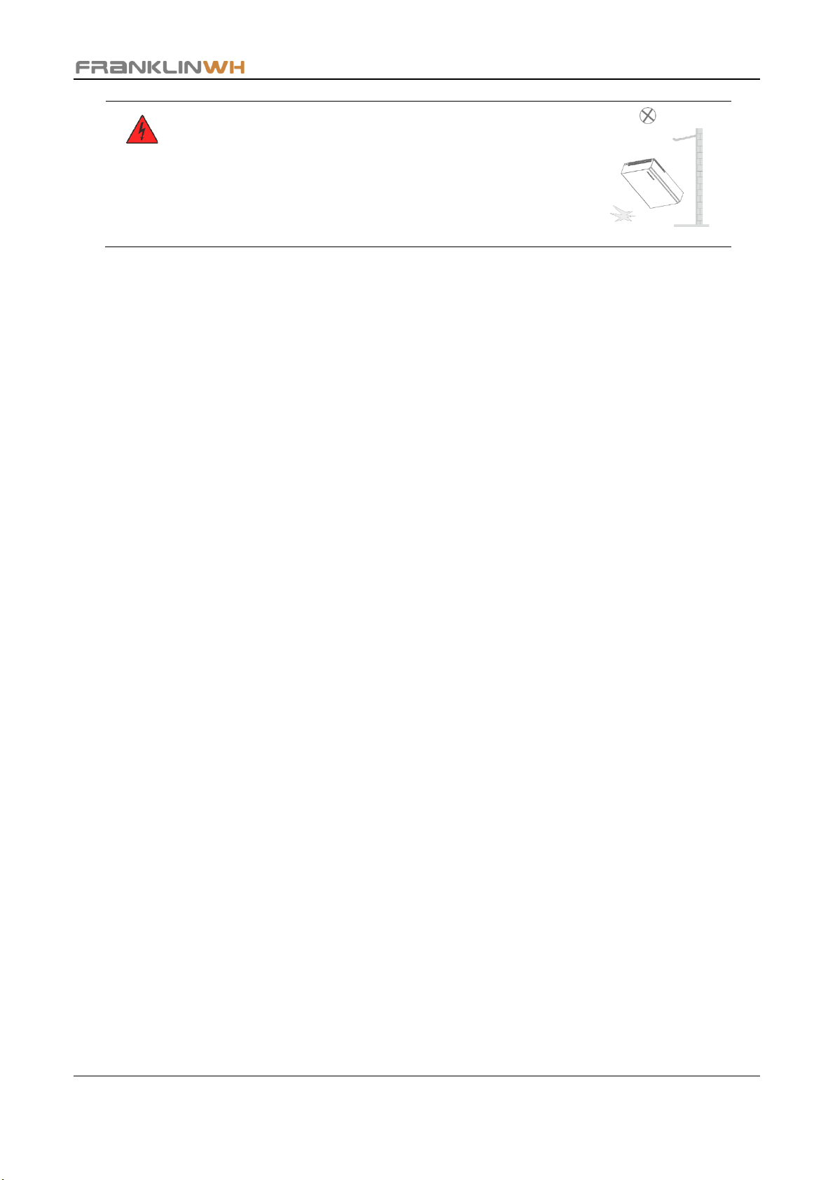
FRANKLINWH Home Power User manual

Franklin Home Power Quick Installation Guide
Version 1.1.03
Issued on: April 26, 2023

Franklin Home Power Quick Installation Guide
©2023 FranklinWH Energy Storage Inc. All rights reserved.
All information in this Manual is subject to the copyright and other intellectual property rights of
FranklinWH Energy Storage Inc. This manual may not be modified, copied or reproduced, in whole or
in part, without the prior written permission of FranklinWH Energy Storage Inc.
Please visit
www.franklinwh.com/support
for the latest Franklin Home Power documents.
All brands and trademarks mentioned in this document are the property of their respective
owners, and their use in this document does not imply the sponsorship or recognition of their
products or services.
Please read this document carefully to ensure the best reliability of the product and your
warranty eligibility. For further information about warranty, please refer to
the
Franklin Home
Power Limited Warranty.
This document is intended for use by professional installation and maintenance service providers
only and no statements, information or recommendations in this document constitute any
express or implied warranty.
Please read this document carefully before installing or using the Franklin Home
Power equipment. Failure to follow any instructions or warnings in this document
may result in damage to the equipment, personal electric shock, severe injury, or
even death.
Product Information
Franklin Home Power (FHP) is composed of aPower, aGate and other electrical components, and
this document applies only to the following products: aPower X and aGate X.
FranklinWH Energy Storage Inc. (“FranklinWH”) reserves the right to make any improvements to
the product, and the contents in this document shall be subject to updates without further
notification.
All images and pictures provided in this Manual are only for demonstration purposes and may
differ in detail from the product, based on the product version.
Feedback
If you have any questions or comments, please send us an email at:
service@franklinwh.com
Disposal of Scrapped Products
Scrapped products (including their internal chemicals and electrical materials) should not be
disposed of with household wastes. Please refer to your local laws and regulations regarding
disposal.

Franklin Home Power Quick Installation Guide
1
Tools
DANGER:
Special care must be taken to protect personal safety.
PPE must be worn during transfer and installation.
WARNING:
Please use proper protective measures, such as foam or protective cloth, keep
aPower X and aGate X well protected from hard objects that may damage their
exterior appearance or body during handling and installation.
Torque Requirements
Screws and their corresponding torques
Screw Type
Cross head cross screwdriver
Tightening torque
M4
PH2
1.03lbf·ft (1.4N·M)
M5
PH2
2.21lbf·ft (3.0N·M)
M6
PH3
4.42lbf·ft (6.0N·M)

Franklin Home Power Quick Installation Guide
2
Please refer to the
Franklin Home Power Installation Guide
for more information. To access
all of our manuals, scan the QR code shown in the picture.
Installation Requirements
Installation Environment
The aPower X and aGate X units can be installed indoors or outdoors.
•If it is installed outdoors, it should be in a sheltered location that is protected from direct
exposure to sunshine, rain and snow for long periods of time.
•Whether installed indoors or outdoors, the noise factor (< 45dB) must be taken into account
when selecting the installation site for each aPower X.
The aPower X and aGate X installation area should be kept dry, cool, and well-ventilated.
The aPower X and aGate X installation area should be protected from access by children and
away from any source of heat and/or fire, water, flammable, explosive materials, dust,
smoke, uneven, and grassland or soft ground.
Cement
board
or slate
shelter
shelter
shelter
shelter
shelter
Direct exposure to sunshine, rain
and snow for long periods of time
Fire or Flammable
Material
Water
Grassland or
Soft ground
Uneven

Franklin Home Power Quick Installation Guide
3
DANGER:
➢Please handle with care.
➢Do not use a dropped product or a product that has been
subjected to a strong impact force. Otherwise, safety risks
(such as cell leakage and electric shock) may arise.
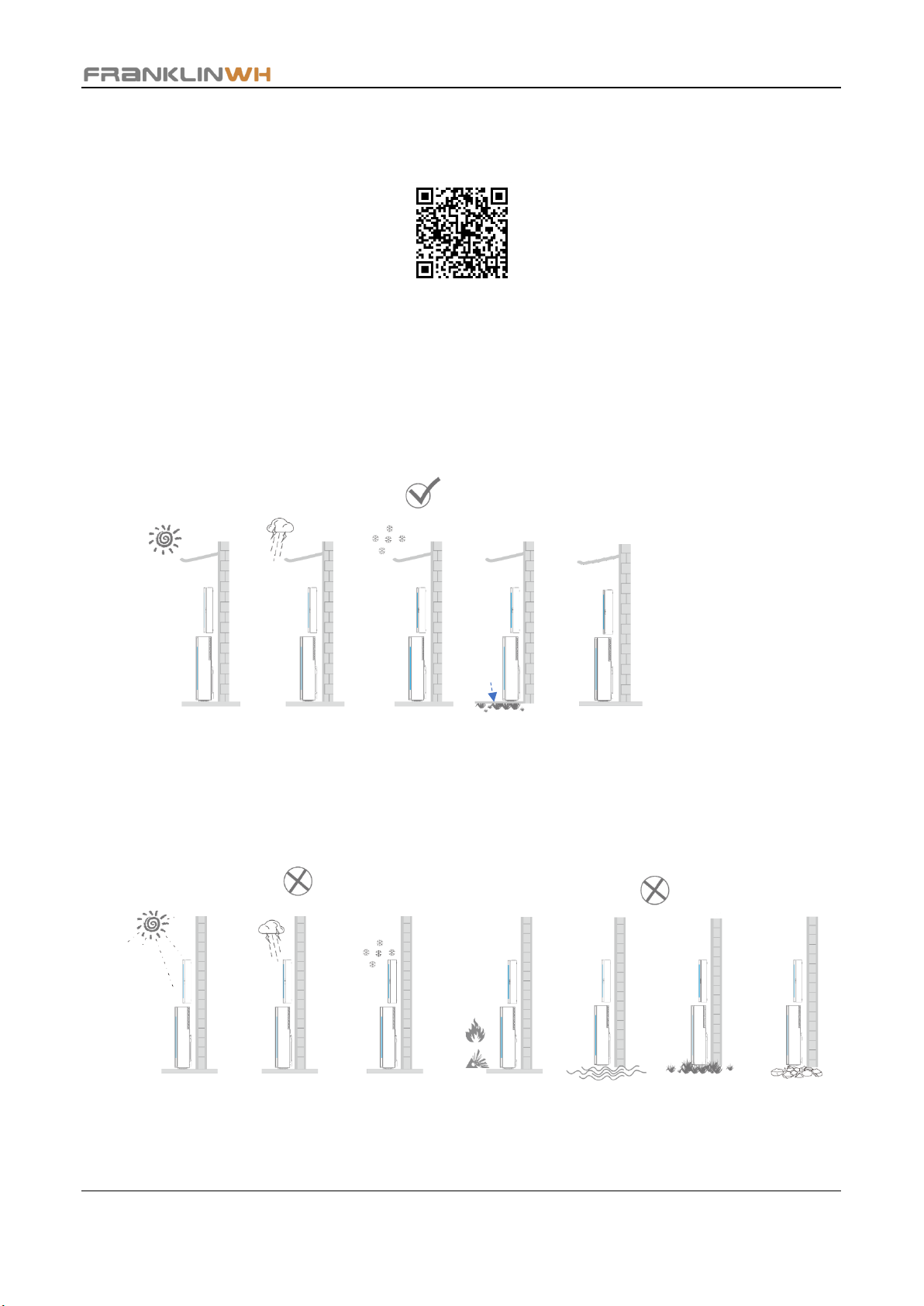
Installation Method
aPower X supports floor-mounted installation and wall-mounted installation. A mounting bracket
is required to hold the equipment to the wall.
aGate X may be wall mounted or embedded in the wall.
Installation Space
•aGate X:
There should be a minimum clearance of 5D (D is the outer diameter of electrical conduits)
from the aGate X bottom to the floor and from the top of the aGate X to the ceiling. The
recommended distance between the bottom of the aGate X and the ground is 48in. (1.22m)
and should not exceed 64in. (1.63m). The maximum distance between the power switch
button on the aGate X and the ground shall not exceed 90in. (2.29m). Please finalize the
installation height in accordance with the specific site conditions.
•aPower X:
There should be a minimum clearance of 5D (D is the outer diameter of electrical conduits)
from the top of aPower X to the ceiling.
When the aPower X is mounted on the wall, the recommended distance between the bottom
of aPower X and the ground is 18in. (0.45m), but not exceed 53in. (1.34m). The maximum
distance between the aPower X switch button and the ground should not exceed 90in.
(2.29m).
The recommended distance between multiple aPower X units is 12in. (0.3m), with a minimum
of at least 6in. (0.15m).
•The recommended clearance in front of the wall in the installation area is 72in. (1.83m). The
installation area should be away from doors, windows, and other operable openings in the
building, as well as separated from HVAC inlets by at least 60in. (1.53m). Please follow your
local laws, regulations and standards during installation.

Franklin Home Power Quick Installation Guide
4
•Maximum allowable cable length between data exchange devices.
Data interchange equipment
Maximum cable length
aPower X and aGate X
98.4ft (30m)
aGate X to Generator
98.4ft (30m)
aGate X to Router
328.1ft (100m)
Split CT
49.2ft (15m)
DANGER:
Avoid drilling holes in the water pipes and cables buried in the wall.
WARNING:
➢Cover the aPower X top heat dissipation hole to protect from gravel dust
during drilling.
➢To avoid damage to equipment, completely shield all aGate X interior
electrical boards and components before you drill or punch holes, to avoid
debris falling into the aGate X. Clean and remove all debris before installing
any components or wiring into the aGate X.
➢Final installation method and spacing to comply with licensed Structural
Engineering Design wherever required.
➢Must comply with all local codes and standards.
Recommended
72in. (1.83m)
aGate X
aPower X
aPower X
aPower X
Recommended
12in. (0.3m)
Minimum
6in. (0.15m)
≥ 5D (D is the outer diameter of electrical conduits)
Recommended
48in. (1.22m)
≥ 5D (D is the outer diameter of electrical conduits)
Recommended
12in. (0.3m)
Minimum
6in. (0.15m)
Recommended
12in. (0.3m)
Minimum
6in. (0.15m)
The distance between the bottom of
aPower X and the ground is not exceed
53in. (1.34m).

Franklin Home Power Quick Installation Guide
5
Introduction to the aGate X
Name
Max
Continuous
Current
Max.
OCPD*
Name
Max
Continuous
Current
Max.
OCPD*
Solar terminal
64A
80A
Grid terminal
160A
200A
aPower terminal
80A
100A
Generator terminal
160A
200A
Smart Circuits 1, 2
40A
50A
Non-backup load terminals
160A
200A
Smart Circuit 3
64A
80A
Backup load terminals
160A
200A
* OCPD: Over Current Protection Device. Bus bar amp rating is 280A.
Wireless
module
aPower
terminal
Generator
assembly terminal
Bonding jumper
Grid relay
location
Generator relay
location
Solar
terminal
EMS
module
Smart Circuit
terminals
Grid terminal
Ground
bar kit
Non-backup
load terminals
Backup load
terminals
Neutral bar kit
aGate X power
switch
WARNING:
The power sources
must be connected to
FHP at the
corresponding ports.

Franklin Home Power Quick Installation Guide
6
Remove the Inner Panel and Door from the aGate X
•Remove the Inner Panel
Use a #3X4” Phillips head screwdriver to unscrew the 4 screws, then remove the aGate X inner
panel and properly store it.
•Remove the Door
Use a #2X4” Phillips head screwdriver to unscrew the 6 countersunk screws, then remove the
aGate X door and properly store it.
Inner Panel
Door
Remove the screws in
the red circle from
inside

Franklin Home Power Quick Installation Guide
7
Mount the aGate X on a Wall
DANGER:
Avoid drilling holes in the water pipes and cables buried in the wall.
WARNING:
➢Cover the aPower X top heat dissipation hole to protect from gravel dust
during drilling.
➢To avoid damage to equipment, completely shield all aGate X interior
electrical boards and components before you drill or punch holes, to
avoid debris falling into the aGate X. Clean and remove all debris before
installing any components or wiring into the aGate X.
➢Add lightning protection measures to the FHP according to NFPA 780,
UL96A, and LPI-175.
➢It is recommended to install cables through the bottom of the aGate X. If
a top inlet cable is installed, waterproof measures must be taken.
Based on the preplanned
installation position and
electrical conduit arrangement,
the installer may choose to
remove the knockouts or plugs
in the aGate X.
Included Sealing washers
(x4) must be installed

Franklin Home Power Quick Installation Guide
8
Remove some aPower X accessories
●Open the aPower X wiring compartment cover, and remove the 3 external cables.
●Remove the power cable conduit hole plug 1 (turn the plug counterclockwise using a Phillips
bit, while keeping the interior fastening nut in position. When loosening, rotate by hand until
the plug is removed.)
●If signal cable hole is needed, remove the cable conduit hole plug 2 using an adjustable wrench
(turn the lock nut counterclockwise until the plug is removed).
WARNING:
Connect cables in accordance with local installation laws and regulations.
Open Clip and
pull it out
Bent-handle ratchet
wrench
Cable conduit hole-plug 1
Cable conduit hole-plug 2
Phillips head

Franklin Home Power Quick Installation Guide
9
Installing the aPower X
Wall
Wall
aPower X
When installing
the bracket, each
bolt needs to use
an M6 spacer.
DANGER: Avoid drilling holes
in water pipes and cables
buried in the wall.
WARNING: Cover the aPower X
top heat dissipation hole during
drilling to protect from gravel dust.
Attach
plates

Franklin Home Power Quick Installation Guide
10
Special Wall/Baseboard Installation
Case 1: Protruding Baseboard
Height > 6in. or the thickness of the
bulge > 1in. (Floor mount)
Case 2: Concave Baseboard
Height > 6in. (Floor mount)
Case 3: Uneven Wall
Solution
Use wooden or steel spacers on the
upper part of the bracket (to keep it
flush with the baseboard).
Solution
Use wooden or steel spacers on
the dented part of the baseboard
(to keep it flush with the wall).
Solution
Use plywood or gypsum
board to level the wall. The
recommended thickness is
0.5in.
*NOTE: These wooden or steel materials are prepared by the installer.
Breakers and Optional Parts
The circuit breakers are optional parts and must be provided by the installer. For more information
about circuit breaker models and manufacturers, see Appendix.
•Standard configuration

Franklin Home Power Quick Installation Guide
11
•Full configuration
Communications Wiring
•Connect a Com Kit (4G & Wifi) cable to Activate the aGate X commissioning
functions.
•Communications Cable Preparation
Smart Circuits
Module (optional)
Generator Module
(optional)
Wireless module
EMS module
Com Kit
(4G & Wifi)
WARNING:
Use only the USB cable
supplied with the
equipment. The aGate X
cannot be activated if this
step is not completed.
①
②
③

Franklin Home Power Quick Installation Guide
12
① Remove the insulation jacket from the cable.
② Fan the wires in the order of 568B
(white/orange, solid orange, white/green, solid
blue, white/blue, solid green, white/brown, solid
brown). Insert the wires into the connector.
③ Crimp the connector using a crimping tool.
•Connect the aGate X to the network for remote access to the FHP
To ensure the reliability of remote communications, it is recommended to insert the home
network cable with an internet connection into the Eth2 port of the EMS module, in order to
enable the remote communications function.
WARNING:
➢
The cable from the household network may only be
connected to the Eth2 port, as Eth1 port is used for
support.
➢The network cable needs to be made on site using
a crimping tool according to the 568B standard.
Bending of a unibody cable inside the aGate X may
prevent the inner cover from closing.
WARNING:
Before connecting the assembled
cable, use a network cable tester
to ensure that the cable is
working correctly.
When testing, the cable must be
disconnected from the device.

Franklin Home Power Quick Installation Guide
13
•Communications connection between the aGate X and the aPower X
When the length of the communications cable between the aGate X and the aPower X is less
than 98ft (30m), a communications cable can be used to connect.
Both the communications cable connection and 20V power supply must be used in
conjunction when the communications cable length between aGate X and aPower X is longer
than 98ft (30m).
WARNING:
When more than one aPower X unit work in parallel mode, it is necessary to remove
the excess matching terminals from all aPower X units along the loop except for the
matching terminal on the last aPower X.
NOTE:
➢If the communications cable shares the same conduit with power wires, please
use a Type 600V TC insulated communication cables (with metal connectors).
➢When the system needs to be connected to the 20V power
supply, the terminal does not need to be removed. Just
press the orange switch of the port, insert the prepared
wire, and then release the switch to complete the wiring.
Network cable
aPower X
1
aPower X
2
aPower X
N (N≤15)
CAN OUT
EMS
…
Connection
Connection
Connection
Remove the matching terminal of
aPower X 1, aPower X 2....
Keep the
matching terminal
-+
20V power
supply
WARNING:
➢Use communications cables in
compliance with 568B.
➢Test with a network cable tester to
ensure that the communications
cable is error-free. Before testing,
ensure that both ends of the
communication cable are
disconnected from the device.

Franklin Home Power Quick Installation Guide
14
Power Wiring Diagram
•Solar Inverter Connections to the aGate X
NOTE: All breakers are to be provided by installer or customer.
L1
L2
Neutral
Ground
L1
L2
Ground
Neutral
According to NFPA 70-250 Grounding and
Bonding Part V, when installed as service
equipment, the neutral and ground should be
bonded together as shown in the picture on
the left. The Neutral-Ground Bonding Jumper
must only be removed if not installed as
service equipment or for test purposes.
WARNING:
➢The solar circuit breaker is
the only interface for the
solar inverter to be
connected to the aGate X.
➢The aGate X has a built-in
solar CT.

Franklin Home Power Quick Installation Guide
15
•Smart Circuit Connections to the aGate X (optional)
1) Wiring of Smart Circuit 1 and Smart Circuit 2 is subject to the following practical
conditions.
➢If Smart Circuit 1 and Smart Circuit 2 connect two 1-pole breakers, connect
the load wires to the Smart Circuit module output terminals on aGate X (L1,
L2, Neutral & Ground), as shown below.
➢If Smart Circuit 1 and Smart Circuit 2 connect one 2-pole breaker, connect the
load wires to the Smart Circuit module output terminals on aGate X(L1, L2 &
Ground). The neutral wire needs to be connected or disconnected according to
the demand of the load, as shown below.
Neutral
Ground
Smart Circuit 1
Smart Circuit 2
L1
L2
Smart Circuit 1
Smart Circuit 2
L2
L1
Neutral
Ground

Franklin Home Power Quick Installation Guide
16
2) Smart Circuit 3 is only used for 240V loads without a neutral wire. No device requiring
a neutral wire should be connected to Smart Circuit 3. Connect the load wires to the
Smart Circuit module output terminals on aGate X (L1, L2 & Ground), as shown below.
•The backup load terminals with a breaker (optional)
Smart Circuit 3
L2
L1
Neutral
Ground
With breaker
L1 L2
L2 L1

Franklin Home Power Quick Installation Guide
17
•The Grid AC Power Connections to the aGate X (optional)
•Generator Power Connections to the aGate X (optional)
DANGER:
After installation of the backup load terminals breaker, grid breaker and
generator breaker, L1 and L2 will swap sides for connections (L2 is located to
the left while L1 is to the right).
NOTE:
➢If aluminum cable is used, the cable connectors need to be treated using
antioxidant.
➢If signal exchange is needed between the generator and the aGate X,
please refer to the generator’s manual.
L1
L2
Neutral
Ground
L2
Neutral
Ground
L1
L1
L2
Neutral
Ground
L1
L2
Neutral
Ground
With breaker
With breaker

Franklin Home Power Quick Installation Guide
18
•aPower X connections to the aGate X (One aPower X unit)
The WAGO terminals of the aPower X can only be connected using 10AWG power wire. The
recommended strip length for the cable connected to the WAGO terminal is 0.47 to 0.55in. (12 to
14mm). To connect the other end of the cable to the breaker, determine the cable stripping length
based on the breaker you configured.
WARNING:
If the stripped length of the cable inserted into the WAGO terminal is too long, some metal
cables may be exposed, which may damage the device or cause electric shock.
aPower X 1
Connection
L1
L2
Neutral
Ground
WAGO
0.47~0.55in.
WAGO
terminal
The WAGO terminals of the aPower X connection
Table of contents
Other FRANKLINWH Storage manuals