Frecon MINITERMINAL FIA-L User manual

Control pod
FRECON
MINITERMINAL FIA-L
INSTALLATION AND USER MANUAL
FRECON, spol. s r.o. Hodkovická 115, 142 00 Praha 4, CZECH REPUBLIC

1. Introduction
FRECON MINITERMINAL - control pod for the FIA-L programmable speed drives combines
keypad and display functions :
• local/remote control selection
• local control (run/stop, forward/reverse, output frequency control resolution : 0,01Hz)
• drive parameter values adjustment and display (LCD screen)
• user sets programming possibility
(i.e. storing all functional parameters into EEPROM for automatic or manual restore)
• frequency reference and actual output frequency monitoring (LCD screen)
• operational status LED indication : run, fwd, rev, local control
• fault codes signalization
• MOUNTING : externally anywhere convenient at a distance permitted by maximum cable
length of 6m between the drive and the pod.
2. General description
control cable (including connector for the
connection to the drive)
four drive operational status LEDs
4-char. LCD display
keypad (9 keys)
3. Connection to the drive
The pod is equiped by a standard control cable terminated by male connector suited for
connection to the female connector of the drive. The standard cable lenght is 1m, the optional
maximum length is 6m.
1

4. Operational status indication
Four red LEDs above the keypad indicate the status of the drive.
- indicates status "RUN" or "STOP", i.e. the activation of the output power bridge
light on : the output power bridge is active (status "RUN")
RUN
light off : the output power bridge is inactive (status "STOP")
- indicates actual control mode
light on : local (keypad) control mode
LOC
light off : remote (terminals) control mode
- FWD, REV indicate the actual and required direction of motor rotation
light on : the actual direction
light flashing : the required but not actual direction of rotation (light of the actual
FWD
REV
direction remains on)
5. Functional keypad description
5.1. Parameters setting keys
Parameters and their values are adjusted by the three keys :
UP
DOWN
The keys UP/DOWN enable :
• selection of parameter code from parameter menu
• parameter value changing
• speed control in local (keypad) control mode
NOTE : - a single keystroke changes the value step by step, depending on
displayed value resolution
- press and hold the key for faster fluent changes
PAR menu / value
The key "PAR" switches between menu-code and actual value of the selected parameter.
Press the "PAR" key to switch to parameter menu. The display will show the actual parameter
code.
Shift in menu using UP/ DOWN keys to see the menu-code of selected parameter.
Press the "PAR" key to display the actual value of selected parameter.
Using UP/DOWN keys change the active parameter setting to required value.
To resume another parameter adjustment, press the "PAR" key again to return to menu.
2

5.2. Control mode selection key
LOC
REM
Two modes are available :
• local (keypad) control
indication LOC : light on
• remote control;without using keypad
indication LOC : light off
NOTE : - During initialization after energising the drive, the remote control mode is
automaticaly selected as the active control mode.
-When switching from the remote control mode to the local control mode, the
operational status command of the drive determinated by previous remote
control (run/stop, direction of rotation and frequency reference value FSET) is
unchanged and used as current operational status command for the local
control.
- The key can be used at any operational status of the drive.
5.3. Parameter sets manipulation keys
PROG
operating parameters storing into the user set
Press the PROG key to store the actual values of all parameters from working area
(memory RAM) into the required user set (memory EEPROM). Data in EEPROM are not
lost when power is disconnected from. The PROG procedure requires the motor to be
stopped (output of the drive is inactive), and the display to show the selected set code
(parameter SET).
If these conditions are not fulfilled, the display will show the corresponding fault code.
(refer to chapter 9. Parameter sets manipulation)
READ
operating parameters reading from the set into the
orkiw ng area
Press the READ key to read the values of all parameters from selected user set (memory
EEPROM) or factory set (memory ROM) into the working area.
The READ procedure requires the motor to be stopped (output of the drive is inactive),
and the display to show the selected set code (value of parameter SET).
It is also assumed that the selected set is not blank and the stored data are compatible
with the software of the drive.
If any of the previous conditions isn´t fulfilled, the corresponding fault code is displayed.
(Refer to chapter 9. Parameter sets manipulation)
5.4. Local control keys
F/R rotation direction switching (local control)
During local control the keystroke on F/R switches the required direction of rotation.
When the drive is stopped, only the indication of preselected direction (LED-diodes
FWD,REV) is switched to oposite direction.
When the drive is running, the keystroke on F/R will cause fluent change of the rotation
direction. First the frequency decreases down (deceleration is driven by parameter DEC),
the original direction indicator lights and the new required direction indicator flashes. After
crossing zero value the output frequency increases up to required value in oposite
direction (the acceleration is driven by parameter ACC), the original direction indicator is
set off and the new actual direction indicator lights.
In the remote control mode the F/R key is ignored.
3

RUN
command RUN - start of the drive (local control)
When the drive is stopped (indicator RUN is off) and local control is selected (indicator
LOC lights), the keystroke on RUN causes the drive to start rotation in selected direction
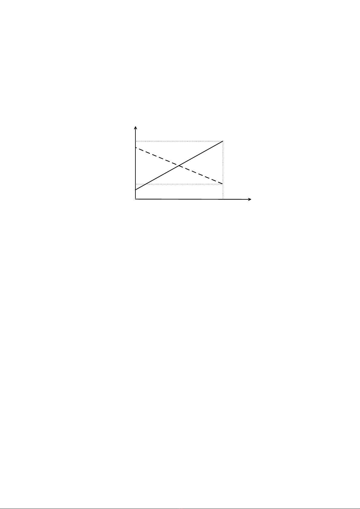
(indicators FWD/REV). The output frequency increases from zero up to required
frequency, which is set by the value of frequency reference FSET. The acceleration is
driven by parameter ACC. (Note: Pressing UP or DOWN key during acceleration causes
immediate stopping of acceleration as the value of frequency reference FSET is
overwriten by the value of current output frequency.)
In the remote control mode the RUN key is ignored.
STOP command STOP - stop of the drive (local control)
In the local mode the keystroke on STOP causes stopping of the drive and deactivation
of the 3-phase output of the inverter. The way of running down is selected by parametr
CSTP:
• CSTP = 0 - ramp mode (controlled run down), i.e. after command STOP the output
frequency decreases down to zero with deceleration driven by parameter DEC. After
reaching zero frequency the drive is still braked for about 30 ms by DC voltage, value
of which is set by parameter U0. Then the output of inverter is deactivated.
• CSTP = 1 - coast to stop mode (free run down), i.e. immediately after command
STOP the output of inverter is deactivated and the motor runs down freely. The
running down time depends on the moment of inertia of connected motor and load.
In the remote mode the STOP key is ignored.
6. Control modes
6.1. REMOTE CONTROL (terminals)
In the remote control mode the drive is operated by control signals connected to terminals.
One analogue control signal (voltage 0-10V / 2-10V, current 0-20mA / 4-20mA, or
potentiometer) and two digital control signals RUN/STOP and FWD/REV are used. The
analogue signal controls the output frequency, i.e. the speed of the drive. The digital signals
control start, stop and direction of rotation of the drive. The analogue signal - to - output
frequency reference conversion is determined by parameters F0, F100 and CINP.
These signals can be controlled by a control system, PLC, FRECON TELECONTROL, or any
other way. If a miniterminal is connected to a drive, the local control keys are ignored, when
the remote control mode is selected.
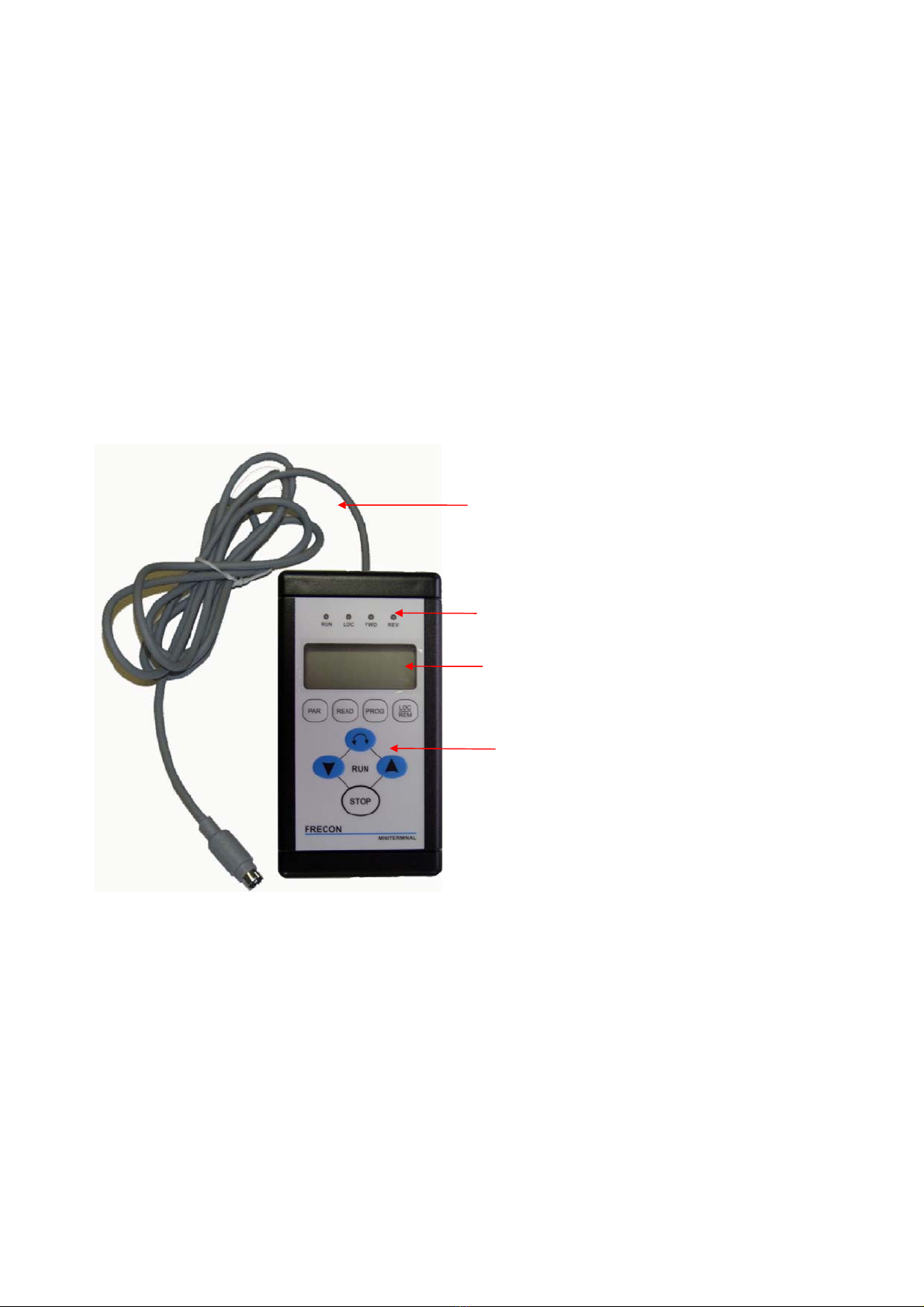
6.2. LOCAL CONTROL (keypad)
In the local control mode the drive is fully operated by the control pod FRECON
MINITERMINAL. The local control keys enable to start and to stop the drive, to change the
direction of rotation, to set the output frequency reference FSET, or to control directly the
actual output frequency FOUT in the full range 0-125 Hz with 0.01 Hz resolution,
independently on the setting of parameters F0, F100 and CINP.
One single keystroke on UP/DOWN keys changes the value of FSET or FOUT by one step,
i.e. 0.01 Hz, longer pressing causes faster continuous changing of the value.
In the local control mode the remote control signals from terminals are ignored.
4

7. Displayable values and adjustable drive parameters table
menu display/setting unit short description
code range
Actual and required output frequency
FOUT 0.00 - 125.0 Hz actual output frequency
FSET 0.00 - 125.0 Hz required output frequency (reference
value)
Analogue control signal to output frequency reference FSET conversion parameters
(Output frequency limit values for remote control)
F0 0.0 - 125.0 Hz req.frequency for 0% analogue signal
F100 0.0 - 125.0 Hz req.frequency for 100% analogue signal
Substitutional output frequency for invalid analogue signal (only for CINP=3)
FERR 0.0 - 125.0 Hz substitutional frequency reference
Dynamic parameters
ACC 0.5 - 500.0 Hz/s max. acceleration of output frequency
DEC 0.5 - 500.0 Hz/s max. deceleration of output frequency
V/f characteristic
FBAS 25.0 - 241.0 Hz base (nominal) frequency (max.voltage
reached)
U0 0.0 - 22.0 % VMAX output voltage for FOUT=0 Hz
U1 1.0 - 30.0 % VMAX output voltage for FOUT= 1/8 FBAS
U2 2.0 - 40.0 % VMAX output voltage for FOUT= 2/8 FBAS
U3 4.0 - 50.0 % VMAX output voltage for FOUT= 3/8 FBAS
U4 6.0 - 60.0 % VMAX output voltage for FOUT= 4/8 FBAS
U5 10.0 - 70.0 % VMAX output voltage for FOUT= 5/8 FBAS
U6 16.0 - 81.0 % VMAX output voltage for FOUT= 6/8 FBAS
U7 32.0 - 93.0 % VMAX output voltage for FOUT= 7/8 FBAS
Configuration parameters
CINP 0,1,2,3 - input analogue signal selection
CSTP 0, 1 - running down mode selection
CRTR 0, 1 - enable user RESET selection
Auxiliary parameter for parameter sets handling
SET UI-0,...,FA-3 - parameter set identification
NOTE : The collection of parameters listed in table (except parameters FOUT, FSET, SET)
forms the „functional parameter set“. The significance of functional parameter sets is
described in chapter 9. Parameter sets manipulation.
5

8. Detailed description of displayable values and adjustable drive
parameters
8.1. Actual and required output frequency
FOUT -actual output frequency value
- display / setting range : 0.00 - 125.0 Hz
When the drive runs the actual output frequency FOUT follows the value of frequency
reference FSET considerating acceleration/deceleration limits ACC/DEC.
In the remote control mode the frequency reference FSET, and consequently the
output frequency, are limited by values F0 and F100. The only exception is possible
when the substitutional output frequency reference FERR outside the limits F0, F100 is
used (refer to description of parameters F0, F100, FERR and CINP).
In the local control mode the actual output frequency can be changed by UP/DOWN
keys in the whole range 0.00-125.0 Hz.
When the drive is stopped, the code „rdy“ is displayed, instead of zero value, indicating
that the drive is stopped but ready to run.
Flashing code „-rdy“ indicates that in stop state, remote control selected and
CINP=2(3), an invalid analogue control signal (decreased under 2.5mA or 1.3V) is
beeing recognized. In this case the command „RUN“ will cause:
• for CINP=2 - immediate shut-down of the inverter output with error code „Er.01“
signalization
• for CINP=3 - running up the drive with the substitutional output frequency
reference set by parameter FERR
Flashing FOUT value indicates that the drive is running using the substitutional
frequency reference. Refer to description of parameters FERR and CINP.
FSET - required output frequency (i.e. frequency reference) value
- display / setting range : 0.00 - 125.0 Hz
In the remote control mode the value of FSET is driven by input analogue contol signal
according to setting of parameters F0, F100 and CINP.
The FSET value can be monitored also during stop state, when the output frequency is
zero and the output of inverter is not active.
Flashing FSET value („0.00“ for CINP=2 or „<FERR>“ for CINP=3) indicates an invalid
input analogue control signal.
In the local control mode the value of FSET can be changed (controlled) only by
UP/DOWN keys, and in the whole range 0.00-125.0 Hz.
8.2. Analogue signal - to - frequency reference conversion parameters
(limit values of output frequency for remote control)
F0- required output frequency related to input analogue signal of 0% of the selected
range, i.e. 0V / 0mA for CINP=1,2 or 2V / 4mA for CINP=3,4
F100 -required output frequency related to input analogue signal of 100% of the selected
range, i.e. 10V / 20mA for all settings of parameter CINP
- setting range : 0.00 - 125.0 Hz
6

The parameters F0 and F100 determine the linear conversion from input analogue control
signal to output frequency reference and consequently the limit values of output frequency
when the remote control mode is selected.
F0 < F100 - standard rising linear conversion characteristic, where higher input signal
determines higher output frequency, F0 determines minimum and F100
maximum output frequency in the remote control mode
F0 > F100 - falling linear conversion characteristic, where higher input signal determines
lower output frequency, F100 determines minimum and F0 maximum output
frequency in the remote control mode
The 100% value is represented by 20mA / 10V of current / voltage input signal.
The 0% value is represented by 0mA / 10V for CINP=1,2 or by 4mA / 2V for CINP=2,3.
100 %0 %
F0
(F100)
F100
(F0)
fout
20mA
(
10V
)
input analogue control signal
0mA (0V) for CINP = 0,1
4mA (2V) for CINP = 2,3
4mA (2V) pro CINP = 2,3
WARNING !
When using the possibility of substitutional output frequency FERR by setting CINP=3, it
should be considered that the value FERR isn´t limited by F0 and F100. Therefore, if an
invalid input signal was recognised and the substitutional value FERR is used as a
frequency reference, the output frequency can be out of the interval limited by values F0
and F100.
8.3. Substitutional output frequency reference (remote control)
FERR - substitutional output frequency reference
- setting range : 0.00 - 125.0 Hz
The parameter FERR is meaningfull only if CINP=3 in the remote control mode. In this
case the value of FERR is used as the substitutional frequency reference, when an invalid
value of input analogue signal was recognised. It should be considered that the value of
FERR, and consequently the value of substitutional output frequency, are not limited by
parameters F0 and F100.
8.4. Dynamic parameters
ACC - maximum acceleration of output frequency in Hz/s
DEC - maximum deceleration of output frequency in Hz/s
- setting range: 0.5 - 500.0 Hz/s
Parameters ACC/DEC limit the output frequency acceleration/deceleration, and
consequently they determine the run up/down times.
Excessively high value of ACC, related to the drived load, could involve an inefficient start
up of a drive, heat stress of a motor, overcurrent and shut-down of the inverter.
Excessively high value of DEC, related to connected moment of inertia, could involve the
overvoltage shut-down of the inverter.
7

8.5. V/f characteristic
FBAS - base frequency
- setting range : 25.0 - 241.0 Hz
Parameter FBAS determines the maximum voltage reaching frequency, and consequently
the constant ratio V/f, flux, and available torque for frequencies under FBAS, if a
compensated linear V/f characteristic is set. For frequencies above FBAS, the output
voltage remains constant (available maximum voltage), and consequently the magnetic
flux and available motor torque decrease („field weakening“).
The „nominal“ setting of FBAS according to nominal (labeled) motor data:
FBAS = Fn* VMAX / Vn, where
Fnis the nominal motor frequency - usually 50 or 60 Hz
Vnis the nominal motor voltage - usually 400/230 V (motor windings connection should be
considered or rearranged for desired value of FBAS)
VMAX is the maximum available output voltage of the inverter, for FIA-L inverters this voltage
is equal to the supply voltage, i.e. VMAX = 230 V
The calculation example for a common motor with delta windings connection ( Vn = 3x230V,
Fn = 50 Hz ):
FBAS = 50 * 230 / 230 = 50 Hz
Setting FBAS above the nominal value, using the same load, involves decreasing of the
magnetic flux and available motor torque, the drive is „softer“, and the slip rises. Setting
FBAS above its nominal value could be recommended only when the motor is loaded by a
soft load lower then the nominal motor load.
Setting FBAS under the nominal value enables partialy to increase available motor torque,
however, the danger of magnetic saturation, overcurrent, high loses and motor
overheating damage rises. Setting FBAS under the nominal value isn’t recommended.
U0, U1, ... , U7 - V/f characteristic curve
- the values U0, U1, ..., U7 are set and displayed as percentage values related to Vmax,
and they determine the output voltages for output frequencies 0, 1/8, 2/8, ..., 7/8 FBAS
- setting ranges are listed in the parameters table, and graphicaly represented in the
following figure.
Voltage values U0-U7 determine the V/f characteristic curve for output frequencies
under FBAS. Together with FBAS, they allow to adjust the V/f characteristic for various
motors and drived loads.
V
Vmax VMA
•U7
•U6
•U5
•U4
•U3
•U2
•U1
•
U0
1/4FBAS 3/4FBAS
1/2FBAS FBAS
(25-241 Hz)
0
f
8

When the constant available motor torque at reduced speed is required, the linear V/f
curve should be used with increased voltage at low frequencies (under 1/2 FBAS) to
compensate the voltage drop in motor windings. Voltage level at very low frequencies
should be set as a compromise of the required torque and the danger of overheating the
motor due to decreased efficiency of the motor selfcooling. When U0 is set above
aproximately 8-12 %VMAX (depending on motor type and power) and the motor is
continuously operated at low frequencies, a speed independent forced ventilation should
be used.
Many loads do not need the constant torque at reduced speed, for example fans,
blowers and pumps. In this cases a nonlinear V/f curve with reduced voltage is more
efficient, since the motor power-factor increases, the wattless current decreases, the
motor is free of overheat stresses, and the efficiency of the whole drive increases.
V V
VMAX VMAX
0 FBAS f 0 FBAS f
Linear V/f curve Fan V/f curve
8.6. Configuration parameters
CINP - determination of input analogue control signal for remote control
(setting of CINP doesn’t affect local control)
• CINP = 0 0 - 20 mA ( 0 - 10 V ) standard
• CINP = 1 0 - 20 mA ( 0 - 10 V ) with analogue signal controlled STOP
When the input analogue signal is driven down under 1mA (0.5V), the
run down and stop of the drive is realised. This enables (for one-
direction operation and permanently activated input RUN/STOP) to
operate the drive by the only one (analogue) signal or potentiometer
(like a potentiometer with OFF position).
• CINP = 2 4 - 20 mA ( 2 - 10 V ) with drive shut-down if an invalid input signal is
recognised
When an invalid input analogue control signal is recognised (under
2.5mA or 1.3V), the drive is immediately shut down, the output status
relay signalizes the fault state, and the corresponding error code is
displayed.
• CINP = 3 4 - 20 mA ( 2 - 10 V ) with constant substitutional frequency if an
invalid signal is recognised
When an invalid input analogue signal is recognised, the value of
FERR is used as the constant substitutional frequency reference.
9

CSTP - run down mode selection for STOP command
• CSTP = 0 ramp mode (controlled run down)
After command STOP, the output frequency continuously decreases
with the constant deceleration set by parameter DEC. After reaching
the zero frequency, the drive is still dc braked for about 30ms, and then
the output of inverter is deactivated.
• CSTP = 1 coast to stop mode (free run down)
Immediately after the command STOP, the output of inverter is
deactivated and the drive runs down freely.
CRTR - RESET mode selection (determines the possibility of reseting the drive after
shut down with or without the necessity of switching off the power supply)
• CRTR = 0 Switching off the power supply for several seconds is the only way to
reset the drive after shut down.
• CRTR = 1 The reset of the drive after shut down can be realised without
switching off the power supply :
a) by pressing STOP key on keypad in local control mode
b) by leading edge of STOP signal (i.e. trailing edge of RUN signal)
in remote control mode
Notes: 1) As the LOC/REM key is not locked, when the drive is shut down, the reset
of the drive after shut down during remote control can be realised also
localy by switching to local control using the LOC/REM key, reseting the
inverter using the STOP key, and switching back (after the „rdy“ code is
signalized) to remote control. However, it is always necessary to find out
and remove the failure reason.
2) When the reset of a drive without switching off the power supply is
performed, the working parameters keep their values as they were before
the reset operation. When switching off and on the power supply, the
working parameters are reinitialised, i.e. reloaded from the basic user set
UI-0, which has been programmed by user into EEPROM.
WARNING : The restart of a drive (i.e. the reactivation of the RUN command) should
be realised after the mechanical stop of the motor to avoid overvoltage /
overcurrent stresses when a low frequency is forced to a running motor.
8.7. Auxiliary parameter for parameter sets identification
SET - parameter set identification
UI-0, UI-1, UI-2, UI-3 - internal user sets of parameters (located in the EEPROM inside
the inverter)
UE-0, UE-1, UE-2, UE-3- external user sets of parameters (located in the EEPROM inside
the FRECON MINITERMINAL control pod, so they enable to
transfer sets of parameters from one inverter to another one)
FA-0, FA-1, FA-2, FA-3 - factory sets of parameters (located in ROM, not reprogrammable
by user), they contain the most frequently used settings of
parameters to help a user with tuning the drive for common use.
See also the next chapter.
10

9. Parameter sets manipulation
Parameter sets memory locations and possibilities of data transfer are drawn in the following
figure : FRECON FIA-L FRECON MINITERMINAL
MEMORY RAM
working (active) memory
(contains actual active
parameters)
FA - 0 UI - 0
UI - 1
UI - 2
UI - 3
FA - 1
FA - 2
FA - 3
UE - 0
UE - 1
UE - 2
UE - 3
READ READPROG
PROGPROG
READ
READ
memory
ROM
memory
EEPROM memory
EEPROM
memory
ROM
The basic
user set
basic
factory
set
Active set
The active set is located in the working (active) memory RAM inside the inverter. The
active set has no identification and contains all active functional parameters. The values
of active parameters can be displayed and adjusted using the FRECON MINITERMINAL
control pod. All active parameters changes can be realised even during motor running
with immediate response in function.
User sets
The contents of the active set (i.e. the active adjustment of all functional parameters) can
be stored (programmed) into any user set, which preserves stored data, when the power
supply is switched off (EEPROM memory). The basic user set, identified as UI-0, is the
most important set as it determines initial setting of active parameters after energising
the inverter.
Storing (programming) the active set to a selected user set
Stop the drive. Using keys PAR,UP,DOWN select parameter SET from menu, display
and set its value to show the selected user set identificator. Then press the PROG key.
During programming, which takes approximatelly two seconds, the display shows the
programming function symbol „Pr“ with rotating segment on the right side. The contents
of active set are not affected by PROG, the old contents of the overprogrammed user set
are lost.
Loading (reading) the contents of selected user set into the active set
Stop the drive, display the SET parameter and adjust it to show the identificator of the
selected user set. Then press the READ key. During loading, the symbol „rd“ with
rotating segment on the right side is displayed. The old contents of active parameters
are lost, the contents of the source user set are not affected by READ operation.
11

Parameter set transfer from one inverter to the other one
As an example, the copy of the basic internal user set UI-0 from the source inverter to
the basic internal user sets UI-0 of two other destination inverters is described in the
following steps :
a) connect the control pod FRECON MINITERMINAL to the source inverter
b) load (READ) the user set UI-0 into the working area (active set)
c) store (PROG) the active set into any external user set, for example into UE-0 (the
copied set is now stored in EEPROM inside the control pod)
d) disconnect the control pod from the source inverter and connect it to one of the
destination inverters
e) load (READ) the external user set UE-0 into the working area (active set)
f) store (PROG) the active set into the destination internal user set UI-0
g) connect the control pod to the second destination inverter and repeat steps e) and f).
Factory sets
Factory sets contain the most common preset values of all functional parameters. The
user can use them or not. Any factory set can be loaded into the working area as active
set, there it can be eventuely modified and stored into any user set. Factory sets cannot
be overprogrammed.
The basic factory set FA-0 contains the most frequently used setting of functional
parameters for the most common drives and loads with linear V/f characteristic. The
factory set FA-1 contains the most frequently used setting of functional parameters for
the most common fans.
Initial setting of the active parameters in the working area
During the initialisation after the inverter is powered on, the data from the basic internal
user set UI-0 are automatically loaded into the working area as active parameters,
independently on wheather the control pod is connected or not. This enables the user to
preset the initial setting of the drive.
If the user set UI-0 is empty (not yet programmed), the contents of the basic factory set
FA-0 are automaticaly loaded instead of UI-0 during the initialisation.
10. Software compatibility
Since several versions of FIA-L control program has been already developed (standard
drives, high speed drives with output frequency up to 500Hz, drives with integrated PI-
regulators of speed dependent technological variables, etc.) and new and higher
software versions can occure in future, the two-level software compatibility checking is
used:
• Software compatibility of an inverter and the connected control pod
This incompatibility is found out immediately after connecting the control pod to the
inverter as the error message „Er.03“ is signalized on the display. This control pod
cannot operate with this inverter.
• Compatibility of the control program and the parameter sets data format
The incompatible data format is found out when the user is trying to load the
incompatible parameter set into the working area. This failure is signalized by error
message „Er.18“ which indicates unusable data. This parameter set can be assumed
as an empty set.
12

11. Failures signalization
When an operational failure or a parameter set manipulation error occures, the
corresponding error code is signalized on the display as a flashing message „Er.NN“,
where NN is the numeric error identifier.
11.1. Operational failures
Er.00 - internal protection inverter shut-down
cause: short circuit, overcurrent, Ixt, overvoltage, undervoltage, damaged
motor, motor or power supply connection failure, motor windings
connection failure
solution: Find out the cause, clear the fault, restart the drive.
Note: A strong interference source near the inverter can cause an
accidental shut-down of the inverter. In this case the interference
source should be removed, eliminated or suppressed using
electromagnetic screen, noise suppressor or any other suitable
interference suppressor or combination of them.
Er.01 - inverter shut-down caused by an invalid input analogue signal during
remote control
cause: The invalid input signal or incorrect parameter CINP setting
solution: Find out the cause, clear the fault, restart the drive.
Er.02 - communication error between inverter and control pod
cause: Connection failure, too long cable, strong interference near the
cable
solution:Quit the failure signalization by pressing any of the keys UP,
DOWN, PAR. If the communication failure repeats, check the
cable and its connection to the drive. If the failure still repeats, try
to find out and eliminate the interference source, or reduce the
cable length.
Er.03 - software incompatibility
cause: The software versions of the inverter and control pod are
incompatible
solution: se the control pod with a compatible software version.
11.2. Parameter sets manipulation errors
Er.10 - Er.17 - EEPROM read/write failure
cause: Accidental or repeated hardware failure
solution: If the failure occures accidentaly, you can quit the
signalization by pressing any of the keys PAR, UP, DOWN,
STOP. If not accidental, the hardware failure requires the
service reparation.
WARNING ! If this failure occures during READ operation (loading the
working area), it is necessary to repeat the READ operation as
the working area may contain incorrect data. The RUN
command must not be executed before correct data has been
loaded into the working area.
Er.18 - unusable data in the selected parameter set
cause: The set is empty (not yet programmed) or incompatible data format
was recognized (such set can be also assumed as an empty set)
solution: Quit the signalization and load (READ) another parameter set.
13

Er.19 - checksum error of the loaded parameter set
WARNING! New data from the selected parameter set were loaded into the
working area, however they shouldn’t be used as they could contain
incorrect data.
solution: Quit the signalization and repeat the READ operation. If the
failure occures again, read another parameter set.
Er.20 - the drive was running when the command READ/PROG was entered
solution: Quit the signalization, stop the drive, and repeat the READ/PROG
command.
Er.21 - the identificator of the selected parameter set must be displayed when the
READ/PROG command is beeing entered.
solution: Quit the signalization, select the parameter SET from menu,
display and set its value to the desired parameter set identificator,
and repeat the READ/PROG command.
Er.22 - It is impossible to overprogram a factory set.
Notes : 1) When the failure Er.00 or Er.01 occures, the immediate automatic shut-
down of the inverter is realised and the motor runs freely down.
Available ways of reseting the drive depend on the parameter CRTR
setting.
2) During the signalization of Er.00 or Er.01, all the keys are locked (ignored),
except the LOC/REM key. If CRTR=1 and local control is switch on, the key
STOP is also unlocked to enable the local RESET operation (refer to
description of the parameter CRTR).
3) During all other failure signalizations, the only unlocked keys are UP,
DOWN, PAR and STOP. Pressing any of them quits the failure
signalization. During local control, the STOP key in addition stops the drive.
14
Table of contents