FREE MOTION GZPL40520 User manual

Visit our website at
www.freemotionfitness.com
CAUTION
Read all precautions and instruc-
tions in this manual before using
this equipment. Save this manual
for future reference.
Model No. GZPL40520
Serial No.
Write the serial number in the
space above for future reference.
Serial Number Decal
QUESTIONS?
As a manufacturer, we are com-
mitted to providing complete
customer satisfaction. If you
have questions, or if there are
missing or damaged parts, we
will guarantee complete satis-
faction through direct assis-
tance from our factory.
TO AVOID DELAYS, PLEASE
CALL DIRECT TO OUR TOLL-
FREE CUSTOMER HOT LINE.
The trained technicians on our
customer hot line will provide
immediate assistance, free of
charge.
CUSTOMER HOT LINE:
1-800-201-2109
Mon.–Fri., 8 a.m.–5 p.m. MST OWNER’S MANUAL

TABLE OF CONTENTS
2
IMPORTANT PRECAUTIONS . . . . . . . . . . . . . . . . . . . . . . . . . . . . . . . . . . . . . . . . . . . . . . . . . . . . . . . . . . . . . . . . 3
WARNING DECAL PLACEMENT . . . . . . . . . . . . . . . . . . . . . . . . . . . . . . . . . . . . . . . . . . . . . . . . . . . . . . . . . . . . . .4
BEFORE YOU BEGIN . . . . . . . . . . . . . . . . . . . . . . . . . . . . . . . . . . . . . . . . . . . . . . . . . . . . . . . . . . . . . . . . . . . . . . 5
ADJUSTMENTS . . . . . . . . . . . . . . . . . . . . . . . . . . . . . . . . . . . . . . . . . . . . . . . . . . . . . . . . . . . . . . . . . . . . . . . . . . . 6
MAINTENANCE . . . . . . . . . . . . . . . . . . . . . . . . . . . . . . . . . . . . . . . . . . . . . . . . . . . . . . . . . . . . . . . . . . . . . . . . . . .7
CABLE DIAGRAM . . . . . . . . . . . . . . . . . . . . . . . . . . . . . . . . . . . . . . . . . . . . . . . . . . . . . . . . . . . . . . . . . . . . . . . . .11
PART LIST . . . . . . . . . . . . . . . . . . . . . . . . . . . . . . . . . . . . . . . . . . . . . . . . . . . . . . . . . . . . . . . . . . . . . . . . . . . . . .12
EXPLODED DRAWING . . . . . . . . . . . . . . . . . . . . . . . . . . . . . . . . . . . . . . . . . . . . . . . . . . . . . . . . . . . . . . . . . . . .13
WARRANTY TERMS AND CONDITIONS . . . . . . . . . . . . . . . . . . . . . . . . . . . . . . . . . . . . . . . . . . . . . . . . . . . . . .14
ORDERING REPLACEMENT PARTS . . . . . . . . . . . . . . . . . . . . . . . . . . . . . . . . . . . . . . . . . . . . . . . . . .Back Cover

3
1. Read all instructions in this manual before
using the strength machine. Use the strength
machine only as described in this manual.
2. It is the purchaser’s responsibility to ensure
that there is enough space around the
strength machine for the intended exercise.
Do not crowd the strength machine.
3. Using the three 9/16” anchor holes to pro-
vide maximum stability, the strength machine
must be anchored to the floor where required
or whenever possible.
4. It is the responsibility of the owner to ensure
that all users of the strength machine are
adequately informed of all precautions.
5. All users of the strength machine should be
instructed to report any injury or strength
machine irregularity to facility staff immedi-
ately.
6. Make sure all parts are properly tightened
before each use of the strength machine.
Replace any worn parts immediately.
7. Use the strength machine only on a level sur-
face. Cover the floor beneath the strength
machine to protect the floor.
8. Make sure that the cable remains on the pul-
leys at all times. If the cable binds as you are
exercising, stop immediately and make sure
that the cable is on the pulleys.
9. Always wear athletic shoes for foot protec-
tion while exercising.
10. Keep hands and feet away from moving
parts. Do not lean on or rest your hands on
the strength machine when it is in use.
11. Keep children under 12 and pets away from
the strength machine at all times.
12. The strength machine is designed to support
a maximum user weight of 350 pounds. Do
not place more than 600 pounds on the
weight bar. Always place an equal amount of
weight on each side of the weight bar. Do not
place more than 315 pounds on the lower
storage bar. Do not place more than 100
pounds on the outside, and 15 pounds on
the inside, of the upper storage bar. Note:
The strength machine does not include
weights.
13. Always secure the weights with the weight
pins when they are mounted on the weight
bar.
14. Always place an equal amount of weight on
each side of the weight bar on the weight arm.
15. Make sure the handles are attached securely
before each use of the strength machine.
16. If you feel pain or dizziness at any time while
exercising, stop immediately and begin cool-
ing down.
WARNING: Before beginning this or any exercise program, consult your physician. This
is especially important for persons over the age of 35 or persons with pre-existing health problems.
Read all instructions before using. ICON assumes no responsibility for personal injury or property
damage sustained by or through the use of this product.
WARNING: To reduce the risk of serious injury, read the following important precautions
before using the strength machine.
IMPORTANT PRECAUTIONS

WARNING DECAL PLACEMENT
4
Part# 7058
DO NOT USE
MACHINE FROM
THIS SIDE
WARNING
The decals shown below have
been placed on the strength
machine in the locations shown.
If a decal is missing or illegible,
please call our Customer
Service Department toll-free at
1-800-201-2109, Monday through
Friday, 8 a.m. until 5 p.m.
Mountain Time, to order a free
replacement decal. Apply the
decal in the location shown.
Decal 1
Shown at 60%
Decal 3
Shown at 70%
Decal 2
Decal 2
Decal 2
Decal 1
Decal 3
Decal 3

5
ASSEMBLED DIMENSIONS:
Height: 48 in. / 122 cm
Width: 50 in. / 127 cm
Depth: 76 in. / 193 cm
Pulley Arm
Handle
Weight Bar
Bumper Ring
Cable
Backrest
Weight Stop
Storage Bar
Anchor Hole
Seat
BEFORE YOU BEGIN
Thank you for selecting the FREEMOTION®PLATE
LOADED SHOULDER strength machine. With unre-
stricted motion you can work your body’s muscle
groups together–the same way you do in real life–and
train more specifically and efficiently. Whether your
goal is to tone your body, build dramatic muscle size
and strength, improve your cardiovascular system, or
train muscles for precise patterns of movement, the
PLATE LOADED SHOULDER will help you to achieve
the specific results you want.
For your benefit, read this manual carefully before
using the strength machine. If you have additional
questions, please call our Customer Service
Department toll-free at 1-800-201-2109, Monday
through Friday, 8 a.m. until 5 p.m. Mountain Time
(excluding holidays). To help us assist you, please
note the product model number and serial number
before calling. The model number is GZPL40520. The
serial number can be found on a decal attached to the
strength machine (see the front cover of this manual).
Before reading further, please review the drawing
below and familiarize yourself with the parts that are
labeled.

6
This section explains how to adjust the strength machine. Make sure all parts are properly tightened each time
the strength machine is used. Replace any worn parts immediately.
ADDING WEIGHTS TO THE WEIGHT ARM
To add resistance to your workout, slide an equal
amount of weight (not included) onto each side of the
Weight Bar (9). Make sure that the weights are
pushed against the Bumper Rings (13). Secure the
weights with the two Weight Pins (2).
Store unused weights on the Storage Bars (10, 11).
The bottom Storage Bar can hold seven 45-pound
weights. The upper Storage Bar can hold four 25-
pound weights on the outside, and three 5-pound
weights on the inside.
9
10
11
13
2
2
ADJUSTMENTS
WARNING: Do not place more
than 600 pounds on the Weight Bar (9).
Always place an equal amount of weight on
each side of the Weight Bar.

7
MAINTENANCE
It is important for safe and trouble-free operation of your FreeMotion Fitness®strength equipment to perform
routine preventative maintenance on a regular basis. Make sure all parts are properly tightened each time the
strength machine is used. Replace any worn parts immediately. The strength machine can be cleaned with a
damp cloth and a mild, non-abrasive detergent. Do not use solvents.
Note: Instruct all personnel to perform equipment inspection and maintenance requirements. Personnel must
record and report any accident. Contact FreeMotion Fitness Customer Service at 1-800-201-2109 with any
questions or concerns.
Use only original FreeMotion Fitness parts for repair or replacement to maintain your machine’s warranty.
FreeMotion Fitness recommends the following procedures:
SCHEDULED MAINTENANCE
DAILY
1. Upholstery—General cleaning:
• Wipe using a soft cloth dampened with a light
solution of household dish detergent and warm
water.
• If necessary, use a soft bristle brush with the
cleaning solution.
• Always remove the cleaning solution using a
cloth dampened with clean water. Rinse often.
2. Upholstery—Difficult stains:
• Spray the stain with a nonabrasive household
cleanser such as FORMULA 409®cleaner, SIM-
PLE GREEN®, or a similar product.
• Rub the area gently and let it set for a few min-
utes.
• Rinse thoroughly with a clean, water-dampened
cloth.
• Repeat if necessary using a soft bristle brush.
Optional method for difficult stains
• Rub the area gently using a soft cloth damp-
ened with rubbing alcohol.
•Rinse thoroughly using a water-dampened
cloth to remove alcohol residue.
CAUTION: When using any cleaning product, try
it first in an inconspicuous place to ensure there
is no damage to the material. Follow directions
and adhere to safety precautions of each manu-
facturer of cleaning agent used. FreeMotion fit-
ness and its vendors cannot be held liable for
damage or injuries resulting from the use or mis-
use of cleaning products.
3. Frames:
• Wipe with a light solution of mild soap and warm
water. Rinse and dry thoroughly.
Important: Do not use abrasive cleaners
because they may scratch the equipment. Strong
cleansers and abrasives will damage decals. Use
caution around decals. Do not use solvents such
as lacquer thinner, kerosene, gasoline or similar
liquids.
4. Stainless Steel Covers:
• Wipe with a light solution of mild soap and warm
water. Rinse and dry thoroughly.
• If desired, or to remove corrosion, use available
commercial stainless steel polishing com-
pounds. Follow manufacturer’s instructions.
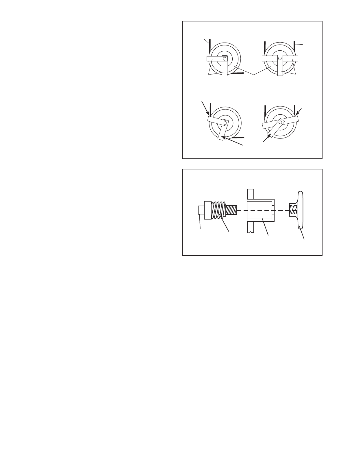
5. Handles:
• Check all handle straps for wear.
• Visually check each strap along the full length
for signs of wear such as cuts, tears or nicks.
Replace the strap immediately if required.
• A “fuzz” on the strap will appear over time and is
not a concern unless it appears to be worn
through strands of the weave.
6. Straps with Rings:
• If a ring is pulling through the strap or tearing
away to the edge of the strap, replace the strap
immediately.
• Check stitching points on straps for tears, worn
spots or separation. Replace the strap if neces-
sary.

8
WEEKLY
1. Hardware: Check all nuts and bolts. Tighten as
required.
2. Cables: Check all cables.
• Check for proper tension.
• Check the entire length of cables by pulling
each handle individually to its fully extended
length and inspect the cable that is exposed on
the exterior of the machine, as well as inspect-
ing the cable inside the cut stack tower.
• Run your fingers along the cable paying close
attention at the bends and attachment points.
• Watch for the following conditions which may
indicate a worn cable in need of replacement:
A. Torn or split cable sheath that exposes the
cable
B. Kinked or severely bent cable
C.A curled or twisted sheath
D.A stretched cable sheath, showing a thin-
ning cross-section
MONTHLYOR AS REQUIRED
1. Grips: Check and replace as needed.
2. Pivoting Shafts: Check to ensure the retainer
rings are in place on both ends of the shafts.
3. Weight Bars: Check to ensure that the bolts are
tight and the bars are secure.
CUSHION ATTACHMENT
NOTE: All FreeMotion Fitness®cushions are fabricat-
ed using a dense plywood with a tee-nut installed for
bolting to the machine framework. Because these tee-
nuts are held by the plywood, they will not withstand
the torque that a standard nut and bolt will. Therefore,
when tightening the cushion bolts, turn until snug and
until the cushion does not move or feel loose.
Overtightening may strip the tee-nut from the plywood
and make it impossible to remove in the future.
CABLE TENSION CHECK
1. Slowly raise and lower the load arm by normal
machine use. The load arm should just come to
rest on the bumper when handle is returned to
the resting position.
• If there is too much tension in the cable, the
load arm will not seat on the bumper.
• If there is not enough tension in the cable, the
load arm will not lift immediately after pulling
one of the handles. Ideally the user
handle/cable should not move more than 1/2"
from its resting position before the load arm
begins to lift.
2. If there is too much or not enough tension in the
cable, adjust the cable as described in CABLE
ADJUSTMENTS, on page 9.
A.
B.
D.
C.

9
ADDITIONAL ADJUSTMENTS
Handle Ends Adjustment– All machines with a
strap and handle
Tools required: 1/8" Allen wrench, cable cutters,
utility knife
Note: Make this adjustment only if the pulley in the
center pulley bracket has been fully adjusted to the
top of the slot and the cable requires more tension.
Note: This adjustment is only for increasing the
cable tension because it requires shortening the
cable. One end is all that requires shortening.
1. Create slack in the cable by pulling the handle
out six to eight inches and propping the empty
load arm in the raised position.
2. Push the black rubber cover off the aluminum
coupler and slide the cover up the cable to con-
tact the pulley in the swivel arm.
3. Loosen the back of the four oval point, 1/4-20-
unc setscrews and pull the cable free.
4. Cut one inch off the cable end with cable cutters.
Note: Using any other tool may flatten or dis-
rupt the end strands so that it may be diffi-
cult to reinsert the cable into the hole of the
coupler.
5. Cut off one inch of the black outer sheath from
the end of the cable.
6. Reinsert the cable and sheath into the coupler
until all of the bare cable is in the hole.
7. Retighten the four setscrews into the threaded
holes. Tighten the setscrews equally until they
contact the cable. Then tighten each screw alter-
nately a 1/4 turn, until all are set to 85
inch/pounds.
8. Slide the black rubber cover over the coupler,
remove the prop and lower the load arm.
9. Check for proper cable tension as described in
CABLE TENSION CHECK, on page 8.
CABLE ADJUSTMENTS
CAUTION: After making any cable adjustment, pull
the handle using a light load and have someone make
sure that the cable is not derailed from a pulley or rub-
bing on a guard (see CABLE GUARD on page 10).
INITIAL ADJUSTMENT
Center Pulley Adjustment– All machines.
Tools required: 9/16"open or box-end wrench, 5/16"
Allen wrench
Note: This is the primary adjustment for all
machines. If this adjustment does not remove the
excess slack, refer to ADDITIONAL ADJUST-
MENTS.
1. Using a 5/16" Allen wrench and a 9/16" open or
box-end wrench, loosen the nut holding the pul-
ley on the center pulley bracket.
2. To increase the tension, slide the pulley upward
in the slot. (To loosen the cable, lower the pul-
ley.)
3. Tighten the nut and check the tension as
described in the CABLE TENSION CHECK, on
page 8. If necessary, readjust the pulley.
Bolt
Nut
Pulley
Slot

10
CABLE GUARDS
Check for alignment periodically to ensure that guards
are not dragging on the cable and that they are per-
forming their intended duty. If the alignment is not
proper, loosen the bolt slightly and readjust as neces-
sary.
Correct Alignment
Incorrect Alignment
Rubbing Contacts
Cable
Out of
Alignment
Guards Guards
Cable
Cable
Pulley
ADJUSTMENT KNOB
If an adjustment knob sticks, it will need to be relubri-
cated. Disassemble the knob and apply a light coat-
ing of lithium grease. Reassemble the knob as shown
in the diagram. If the adjustment knob still does not
function properly, the spring may need to be replaced.
To order a new spring, refer to ORDERING
REPLACEMENT PARTS on the back cover of this
manual.
Adjustment Knob Diagram
Adjustment
Pin Spring Housing Knob

11
CABLE DIAGRAM
The cable diagram shows the proper routing of the
cable. Use the diagram to make sure that the cable
and the cable traps have been assembled correctly. If
the cable has not been correctly routed, the strength
machine will not function properly and damage may
occur. The numbers show the correct route for the
cable. Make sure that the cable traps do not touch
or bind the cable.
1
2
3
4
6
5
8
9
7

12
Note: “#” indicates a non-illustrated part. Specifications are subject to change without notice. See the back cover
of the owner’s manual for information about ordering replacement parts.
Key No. Qty. Description Key No. Qty. Description
11 Base
2 2 Weight Pin
3 1 Left Arm
4 1 Right Arm
5 2 Pulley Arm
6 1 Backrest
7 1 Seat
8 1 Weight Arm
9 1 Weight Bar
10 1 Short Storage Bar
11 1 Long Storage Bar
12 1 Pulley Bracket
13 5 Bumper Ring
14 2 Handle
15 2 Cable Clip
16 5 Pulley with Bushing
17 4 Pulley Plate
18 2 Bungee Cord Clip
19 2 Weight Stop
20 4 Bungee Cord Tie
21 2Bumper
22 61” Bearing
23 6Cable Trap
24 4 Pulley
25 1Small Pivot Rod
26 1Large Pivot Rod
27 43/8” x 1” Bolt
28 13/8” x 1 1/4” Bolt
29 2 3/8” x 4” Bolt
30 2 1” Nylon Washer
31 5 3/8” x 3/4” Bolt
32 3 1/2” x 1 1/4” Bolt
33 4 1” Retainer Ring
34 3 3/8” x 1 3/4” Bolt
35 2 #10 x 1/2” Screw
36 2 3/8” x 2” Bolt
37 2 Trunnion
38 2 5/8” Retainer Ring
39 6 3/8” Nylon Locknut
40 2 5/8” Bearing
41 2 1” Wave Washer
42 2 1” Washer
43 1 Cable
44 2 Bungee Cord
45 2 Coupler
46 2 Coupler Cover
47 8 1/4” Set Screw
48 2 Eyebolt
49 4 Pinch Nut
50 21/2” Bearing
51 21 1/8” Retainer
52 41/2” Nylon Locknut
53 4 1/2” x 4 1/2” Bolt
54 417mm Retainer Rings
55 25/8” Washer
56 1Rectangular Bumper
57 2#8 x 3/4” Self-tapping Screw
# 1 Owner’s Manual
PART LIST—Model No. GZPL40520 R0204A

EXPLODED DRAWING—Model No. GZPL40520 R0204A
15
43
46
45
49
50
49 48
51
47
47
43
46
45
49
50 49
48
51
47
47
11
10
2
2
14
13
32
32
19
44
20
18
35
52
32
44
20
18
22
33
42
41
5
16
37
22
53
16
4
21
31
1
21
28
29
27
29
31
17
24
23
24
23
17
31
7
6
17
23
24
24
23
17
9
22
22 37
41
42
33
5
16
16
3
39
36
52
35
31
31
39
36
53
39
34
8
34
39
26
22
33
33
25
39
16
12
34 40
38
38
39
54
54
54
54
55
55
30
30
23
23
57
56
13

14
WARRANTY TERMS AND CONDITIONS
Limited Warranty on Commercial Equipment
FreeMotion Fitness, Inc. warrants that all new equipment will be free of manufacturing defects in workman-
ship and materials, becoming effective at the date of original installation. Parts repaired or replaced under
the terms of this warranty will be warranted for the remainder of the original warranty period only. Labor
must be performed at a FreeMotion Fitness commercial service facility or by a FreeMotion Fitness author-
ized commercial service provider.
Terms and Conditions of Coverage
1. Warranty applies only while:
(A) it remains in the possession of the original purchaser and proof of purchase is demonstrated,
(B) it has not been subject to accident, misuse, abuse, improper service, or modification, and
(C) claims are made within the warranty period.
2. All coverage is provided by specific Product according to the guidelines listed below.
3. If the Product or any covered part must be returned to a service facility for repairs, We, FreeMotion
Fitness, Inc., will pay all transportation and insurance charges for the first year. We must approve trans-
portation and insurance previous to shipping. You are responsible for transportation and insurance
charges during the remaining years.
4. We will ship to you any new or rebuilt replacement part or component, or, at our option, replace the
Product. Such replacement parts are warranted for the remaining portion of the original warranty period.
5. This warranty does not cover damage or equipment failure caused by failure to provide reasonable and
necessary maintenance as outlined in the owner’s manual. Any failures or damage caused by unautho-
rized service, misuse, accident, negligence, improper assembly or installation, debris resulting from any
destruction activities in the Product’s environment, rust or corrosion as a result of the Product’s location,
alterations or modifications without written authorization, or by failure on your part to use, operate, and
maintain the Product as set in your owner’s manual will void this warranty. All terms of this warranty
are void if this Product is moved beyond the continental borders of the United States of America
(excluding Alaska, Hawaii, and Canada) and are then subject to the terms provided by that coun-
try’s local authorized FreeMotion Fitness representative.
6. During the labor period, FreeMotion Fitness, Inc. compensates Servicers for warranty trips within their
normal service area to repair Product at the consumer’s location. You may be charged a trip charge out-
side the service area.
7. FreeMotion Fitness, Inc. Limited Warranty service may be obtained by contacting Customer Care at
1-800-201-2109.
8. Product limited warranty is void when Product is installed in a country other than where sold.
Limited warranty does not apply to:
1. Repairs performed on Product with missing, altered, or defaced serial numbers.
2. Service calls to correct installation of the Product or instruct owners on how to use the Product.
3. Repair pick-up, delivery, or freight charges other than specified above.
4. Any labor costs incurred beyond the applicable labor warranty period.
Limited Warranty
Parts are warranted to be free from defects in materials and workmanship for the duration of the warranty
period as described below. Labor is warranted for one year except for upholstery and grips.
• 10 years: Structural frame
• 3 years: Bearings, guide rods, pulleys, cams, weight stacks
•1 year: Cables
• 120 days: Upholstery, grips, selector pins, knobs, decals

15
Your Responsibility
Retain proof of purchase; use, operate, and maintain the Product as specified in the Owner’s Manual; noti-
fy Customer Care of any defect within 10 days after discovery of the defect; if instructed, return any defec-
tive part for replacement, or, if necessary, the entire Product for repair.
Owner’s Manual
It is very important that you read the Manual before operating the Product. Remember to perform the peri-
odic maintenance requirements specified in the Manual to assure proper operation and your continued sat-
isfaction.
Receipt of Parts and Service
Simply call Customer Care toll-free at 1-800-201-2109, Monday through Friday from 8 a.m. to 5 p.m.
Mountain Time, and give your name, address, and the serial number of your Product. A representative will
tell you how to get a replacement part, or, if necessary, arrange for service where your Product is located
or advise you on how and where to ship the Product for service.
Before Shipping:
1. Obtain a Return Authorization Number (RA#) from Customer Care.
2. Securely pack your Product.
3. Write the RA# on the outside of the carton.
4. Insure the Product.
5. Include a letter explaining the defect or problem and a copy of your proof of purchase if you believe the
service is covered by warranty.
Exclusive Warranty
FreeMotion Fitness, Inc. is not responsible or liable for indirect, special, or consequential damages arising
out of, or in connection with, the use or performance of the Product or damages with respect to any eco-
nomic loss, loss of property, loss of revenues or profits, loss of enjoyment or use, costs of removal or
installation, or other consequential damages of whatsoever nature. Some states do not allow the exclusion
or limitation of incidental or consequential damages. Accordingly, the above limitation may not apply to you.
The warranty extended hereunder is in lieu of any and all other warranties and any implied warranties of
merchantability or fitness for a particular purpose is limited in its scope and duration to the terms set forth
herein. Some states do not allow limitations on how long an implied warranty lasts. Accordingly, the above
limitation may not apply to you.
Unauthorized Changes to Warranty
No one is authorized to change, modify, or extend the terms of this limited warranty.
State Laws
This warranty gives you specific legal rights and you may have other rights which vary from state to state.

Part No. GZ7055 R0204A Printed in USA © 2003 ICON Health & Fitness, Inc.
To order replacement parts, simply call our Customer Service Department toll-free at 1-800-201-2109, Monday
through Friday, 8 a.m. until 5 p.m. Mountain Time (excluding holidays). To help us assist you, please be pre-
pared to give the following information:
1. The MODEL NUMBER of the product (GZPL40520)
2. The NAME of the product (FREEMOTION®PLATE LOADED SHOULDER strength machine)
3. The SERIAL NUMBER of the product (see the front cover of this manual)
4. The KEY NUMBER and DESCRIPTION of the part(s) (see the PART LIST and EXPLODED DRAWING on
pages 8 and 9 of this manual)
ORDERING REPLACEMENT PARTS
Table of contents
Other FREE MOTION Home Gym manuals

FREE MOTION
FREE MOTION 620 BE User manual

FREE MOTION
FREE MOTION EPIC LEG EXTENSION User manual

FREE MOTION
FREE MOTION Epic Chest User manual

FREE MOTION
FREE MOTION Epic GZFI8063.5 User manual

FREE MOTION
FREE MOTION 220 BE User manual

FREE MOTION
FREE MOTION Epic PLATE LOADED LEG PRESS User manual

FREE MOTION
FREE MOTION GZFM6006.4 User manual
Popular Home Gym manuals by other brands

York Fitness
York Fitness Aspire owner's manual

Christopeit Sport
Christopeit Sport WRT2000 Assembly and operating instructions

Matrix
Matrix ULTRA Single-Station Strength owner's manual

Taurus
Taurus Multi-gym UltraForce Assembly and operating instruction

ParaBody
ParaBody PBF010A Assembly instructions

Klarfit
Klarfit Ultimate Gym 9000 manual