Freecom FC TapeWare AIT-450i User manual


Notice
This document contains proprietary information which is protected by copyright. All rights reserved. No part of this
document may be photocopied, reproduced or translated to another language without prior written consent of
Sony. The information contained in this document is subject to change without notice.
SONY MAKES NO WARRANTY OF ANY KIND WITH REGARD TO THIS DOCUMENT. Sony shall not be liable
for errors contained herein, or indirect, special, incidental or consequential damages in connection with the
furnishing, performance, or use of this document.
© Copyright 2004 Sony Corporation
For further information , please contact the appropriate Sony location listed below;
Sony Corporation
Electronic Devices Marketing Group
Tape Streamer Marketing Section
Gate City Osaki West Tower
Osaki East Tec.
1-11-1 Osaki Shinagawa-ku, Tokyo, 141-0032 Japan
TEL: (81) 3-5435-3486 FAX: (81) 3-5435-3565
Sony Korea Corporation.
34F, ASEM Tower, World Trade Center, 159-1
Samsung-Dong, Kangnam-Ku, Seoul, 135-798 Korea
TEL: 82-2-6001-4249
Sony Electronics Inc.
3300 Zanker Road, San Jose, California 95134,
U.S.A.
TEL: (1) 408-432-1600 FAX: (1)408-955-5533
TLX: 171331 SJESONY
Sony Taiwan Limited, ODS Dept. DS Sect.
5F, 145 Changchun Road, Taipei 104, Taiwan
TEL: (886) 2-2522-7953 FAX: (886) 2-2522-2237
Sony Europe Semiconductor &
Electronic Solutions
The Heights, Blookland, Weybridge, Surrey KT13
OXW
TEL: (01932) 81-6000 FAX: (01932) 81-7001
Sony Corp. of Hong Kong Ltd. Beijing Rep. Office
Electronic Device Marketing Hong Kong, Computer
Peripheral Division
Tower A, 11/F Full Link Plaza, No.18
Chaoyangmenwai Ave., Beijing, 100020 P.R.C.
TEL: 86-10-6588-0633 FAX: 86-10-6588-0855
Sony of Canada Ltd.
Communications & Information Systems Group
Storage Marketing
115 Gordon Baker Road
Toronto, Ontario M2H 3R6
TEL: (416) 499-1414 FAX: (416) 495-3331
Sony Recording Media & Energy Latin America
Storage Drive Group
5201 Blue Lagoon Drive Suite 390
Miami, FL 33126, U.S.A.
TEL: (1) 305-260-4027 FAX: (1)305-260-7850
Sony Electronics Singapore Pte Ltd
Electronic Devices Marketing (Singapore)
Computer Peripherals Division Enterprise
Storage Solutions Department
2 International Business Park #01-10
Tower One The Strategy Singapore 609930
TEL: +65 6544 7322 FAX: +65 6544 7392
Sony Brasil Ltda.
Informatica Division
Rua Inocencio Tobias, 125-Bloco A 01144-000
Sao Paulo, SP Brazil
TEL: (55) 11-3613-9140 FAX: (55) 11-9158-8200

Changing List
Page Clause Title Modify Add Delete Remarks
SDX-450V Series Ver. 1.0 SEPTEMBER, 2004 (RELEASE)

This page intentionally left blank.

SDX-450V series Ver.1.0 Table of Contents
Table of Contents
1. Introduction
1.1. About this Product Specification Manual 1- 1
1.2. Introducing the SONY AIT Technology 1- 1
1.3. Features of the Drive 1- 2
1.4. Reference 1- 3
1.4.1. How to get ECMA-222, 246, 291 Standard Document 1- 3
2. Specifications
2.1. Specifications 2- 1
2.1.1. Dimensions 2- 1
2.1.1.1. Mounting Holes 2- 2
2.1.2. Weight 2- 4
2.1.3. Connectors 2- 4
2.1.3.1. SCSI Cables and Terminators 2- 4
2.2. Environmental Specifications 2- 4
2.2.1. Temperature and Humidity Range 2- 4
2.2.2. Altitude 2- 5
2.2.3. Suspected Particulate 2- 5
2.2.4. Vibration 2- 5
2.2.5. Shock 2- 5
2.2.6. Acoustic Noise 2- 5
2.2.7. EMC 2- 5
2.2.8. Orientation 2- 5
2.3. Performance Specification 2- 6
2.3.1. Data Capacity 2- 6
2.3.2. Data Transfer Rate 2- 7
2.3.2.1. Sustained Data Transfer Rate to and from the Tape 2- 7
2.3.2.2. Burst Transfer Rate to and from the SCSI Bus 2- 7
2.3.3. Initialize Time 2- 7
2.3.4. Load Time 2- 7
2.3.5. Unload Time 2- 7
2.3.6. Search Time 2- 7
2.3.7. Rewind Time 2- 8
2.3.8. Error Rate 2- 8
2.3.9. Retry Limits on Rewrites 2- 8
2.3.10. Definition of Failure 2- 8
2.3.11. Mean Time Between Failures 2- 8
2.3.12. Mean Time to Repair 2- 8
2.3.13. Component Life 2- 8
2.3.14. Durability 2- 8
2.4. Safety 2- 9
2.4.1. Conditions ofAcceptability 2- 9
2.5. Installation Requirements 2- 9
2.5.1. Power Requirements 2- 9
2.6. Data Compression 2- 10

SDX-450V series Ver.1.0 Table of Contents
3. Installation
3.1. Installation Guide 3- 1
3.1.1. SCSI ID Number Jumper 3- 2
3.1.2. Termination Power Switch 3- 2
3.1.3. Parity Disable Jumper 3- 3
3.1.4. Data Compression ON Switch 3- 3
3.1.5. Power Connector 3- 3
3.1.6. SCSI 68 pin Connector 3- 3
3.1.7. Attaching and Removing the Dust Cover 3- 6
3.1.7.1. Attaching the Dust Cover 3- 6
3.1.7.2. Removing the Dust Cover 3- 7
4. Operation
4.1. Summary of LED Indications 4- 1
4.2. Operator Action 4- 2
4.2.1. Powering up the SDX-450V 4- 2
4.2.2. Inserting Cassettes 4- 2
4.2.3. Removing Cassettes 4- 2
4.2.4. Hard Reset Hole 4- 2
4.2.5. Write-Protecting Cassettes 4- 2
4.3. Internal Function 4- 3
4.3.1. The Load Sequence
(Effective for SDX-T3N,TAITE-20N and TAIT1-40N) Refer to
12.2.1. Fast Media Load/Unload (Effective for SDX1-25C,
SDX1-35C and TAIT1-40C, MIC cassette)
4- 3
4.3.2. The Unload Sequence
(Effective for SDX-T3N,TAITE-20N and TAIT1-40N) Refer to
12.2.1. Fast Media Load/Unload (Effective for SDX1-25C,
SDX1-35C and TAIT1-40C, MIC cassette)
4- 3
4.3.3. Power-Fail or SCSI Reset Handling 4- 3
4.3.4. Diagnostic and Normal Status Displays 4- 4
4.3.4.1. Diagnostic Status Display 4- 4
4.3.4.2. Normal Status Display 4- 4
4.4. Tape Format 4- 5
4.4.1. Tape Partitions 4- 5
4.4.1.1. Formatting partitions 4- 5
4.5. Maintenance, Troubleshooting and Service 4- 6
4.5.1. Head Cleaning 4- 6
4.5.1.1. Message when cleaning cassette is necessary 4- 6
4.5.1.2 The condition of cleaning request 4- 6
4.5.1.3. Usage of cleaning cassette 4- 6
4.5.2. Troubleshooting Guide 4- 6
4.5.2.1. Operational Problems 4- 6
4.5.2.2. Read/Write Problems 4- 9
4.5.2.3 Replace Tape 4- 9
4.5.2.4. Media Warning 4- 9

SDX-450V series Ver.1.0 Table of Contents
4.5.3. Clearance for Service 4- 9
4.5.4. Packaging for Return to Sony 4- 9
5. SCSI Interface
5.1. Introduction 5- 1
5.1.1. Overview of the SCSI Interface 5- 1
5.1.2. Supported Messages 5- 1
5.1.3. Supported and Unsupported Commands 5- 1
5.2. SCSI BUS Operation 5- 2
5.2.1. Typical SCSI Operation 5- 2
5.2.2. Disconnect 5- 3
5.3. Message Specification 5- 4
5.3.1. COMMAND COMPLETE (00h) 5- 4
5.3.2. EXTENDED MESSAGE (01h) 5- 5
5.3.2.1. SYNCHRONOUS DATATRANSFER REQUEST (01h) 5- 5
5.3.2.2. WIDE DATATRANSFER REQUEST 5- 6
5.3.3. SAVE DATAPOINTER (02h) 5- 8
5.3.4. RESTORE POINTERS (03h) 5- 8
5.3.5. DISCONNECT (04h) 5- 8
5.3.6. INITIATOR DETECTED ERROR (05h) 5- 8
5.3.7. ABORT (06h) 5- 9
5.3.8. MESSAGE REJECT (07h) 5- 9
5.3.9. NO OPERATION (08h) 5- 9
5.3.10. MESSAGE PARITY ERROR (09h) 5- 9
5.3.11. BUS DEVICE RESET (0Ch) 5- 9
5.3.12. IDENTIFY (80h-FFh) 5- 10
5.3.13. IGNORE WIDE RESIDUE (23h) 5- 10
5.4. Status Specification 5- 10
6. Command Specification
6.1. ERASE 19h 6- 2
6.2. INQUIRY 12h 6- 3
6.3. LOAD / UNLOAD 1Bh 6- 8
6.4. LOCATE 2Bh 6- 9
6.5. LOG SELECT 4Ch 6- 10
6.6. LOG SENSE 4Dh 6- 12
6.6.1. The Log Page Descriptor 6- 14
6.6.2. The Log Parameter Descriptor 6- 15
6.6.3. Supported Log Pages 6- 16
6.6.3.1. Summary List of Supported Pages 6- 17
6.6.4. Write and Read Error Counters Pages 6- 17
6.6.5. Last N Error Events List 6- 18
6.6.6. Tape Log Page (Sony Unique) 6- 19
6.6.7. Tape Capacity Log Page 6- 21
6.6.8. Drive Usage Log Page (Sony Unique) 6- 22
6.6.9. Read and Write Frame Error Counter Page 6- 23

SDX-450V series Ver.1.0 Table of Contents
6.6.10. Data Compression Transfer Log Page 6- 24
6.6.11. AIT Log Page (3Ch) 6- 25
6.6.12. MIC Fixed Length Information page (3Dh) 6- 28
6.6.13. MIC Variable Length Information Page (3Eh) 6- 33
6.7. MODE SELECT 15h 6- 35
6.7.1. Disconnect-Reconnect Page (02h) 6- 38
6.7.2. Data Compression Control Page (0Fh) 6- 39
6.7.3. Device Configuration Page (10h) 6- 41
6.7.4. Medium Partitions Parameter Page (11h) 6- 43
6.7.5. Medium Partitions Parameter Page
(for multi-partitioned tapes)(11h) 6- 45
6.7.6. Informational Exceptions Control Page (1Ch) 6- 48
6.7.7. AIT Device Configuration Page (31h) 6- 49
6.7.8. Append Partition (32h) 6- 51
6.7.9. Delete Partition (33h) 6- 54
6.8. MODE SENSE 1Ah 6- 58
6.8.1. Mode Sense 31h (AIT Device Configuration Page) 6- 60
6.9. PERSISTENT RESERVE IN 5Eh 6- 61
6.10. PERSISTENT RESERVE OUT 5Fh 6- 65
6.11. PREVENT ALLOW MEDIUM REMOVAL 1Eh 6- 67
6.12. READ 08h 6- 68
6.13. READ BLOCK LIMITS 05h 6- 70
6.14. READ BUFFER 3Ch 6- 71
6.15. READ POSITION 34h 6- 73
6.16. RECEIVE DIAGNOSTIC RESULTS 1Ch 6- 75
6.17. RELEASE UNIT 17h 6- 77
6.18. REPORT DENSITY SUPPORT 44h 6- 78
6.19. REPORT LUNS A0h 6- 81
6.20. REQUEST BLOCK ADDRESS 02h 6- 82
6.21. REQUEST SENSE 03h 6- 83
6.22. RESERVE UNIT 16h 6- 91
6.23. REWIND 01h 6- 92
6.24. SEEK BLOCK 0Ch 6- 93
6.25. SEND DIAGNOSTIC 1Dh 6- 94
6.26. SPACE 11h 6- 96
6.26.1. CHECK CONDITION 6- 98
6.26.2. Sony SDX-450V Unique Implementation for SPACE 6- 98
6.26.2.1. Super High Speed Search 6- 98
6.26.2.2. Data Buffer Management 6- 98
6.27. TEST UNIT READY 00h 6- 99
6.28. VERIFY 13h 6- 100
6.29. WRITE 0Ah 6- 102
6.30. WRITE BUFFER 3Bh 6- 104
6.31. WRITE FILEMARKS 10h 6- 106

SDX-450V series Ver.1.0 Table of Contents
7. Drive Diagnostics
7.1. Overview 7- 1
7.2. Diagnostic Test 7- 1
7.2.1. Power-on Self Test 7- 1
7.2.2. SEND DIAGNOSTIC command – Self Test 7- 2
7.2.3. SEND DIAGNOSTIC command – Individual Test 7- 2
7.2.4. Diagnostic Test Number Summary 7- 3
7.2.5. RECEIVE DIAGNOSTIC RESULT command 7- 4
7.2.6. Diagnostics Results Reference 7- 6
7.2.7. Diagnostic Tests RequiringAdditional Parameters 7- 7
7.2.7.1. Error Rate Test (02) Diagnostic Parameters 7- 7
7.2.7.2. Read Data Exerciser (43h) Diagnostic Parameters 7- 8
8. Appendix A: ASC & ASCQ Alphabetic Order 8- 1
9. Appendix B: ASC & ASCQ Numeric Order 9- 1
10. Appendix C: SCSI Commands (OP Code Order) 10- 1
11. Appendix D: ASC & ASCQ for AIT (Sony Unique) 11- 1
12. Appendix E: Introduction to AIT-2 contact type MIC
12.1. MIC Data Structures 12- 1
12.1.1. MIC Header 12- 1
12.1.2. System Log 12- 1
12.1.3. User Volume Note & User Partition Note 12- 2
12.1.4. Super High Speed Search Map 12- 2
12.1.5. Example of Usage 12- 2
12.2. Functional Benefits 12- 3
12.2.1. Fast Media Load / Unload 12- 3
12.2.2. Super High Speed Search 12- 4
12.2.3. Data Integrity / Media Management 12- 5
12.2.3.1. SampleApplication for MIC 12- 5
13. Appendix F: Miscellaneous Notes to AIT-2 contact type MIC
13.1. Partition Numbering in the DDS Emulation Mode 13- 1
13.2. AIT Log Sense 13- 1
13.3. Write Protection Tab on SDX2 cassette 13- 1
13.4. Unique Serial Number in MIC 13- 1
13.5. AIT Cassette Manufacturer ID in MIC 13- 1
13.6. AIT Cassette Secondary ID in MIC 13- 2
13.7. Unreadable MIC 13- 2
13.8. Example SCSI Command Sequence for MIC 13- 2
13.8.1. How to create User Notes inAIT-2 MIC 13- 2

SDX-450V series Ver.1.0 Table of Contents
13.8.1.1. Procedure for Writing User Data on MIC using LOG SELECT
Command 13- 4
13.8.2. User Data Length: 380 byte 13- 5
13.8.2.1. Procedure of Reading User Data on MIC using LOG SENSE
Command 13- 5
13.8.3. How to Update the User Volume Note 13- 6
13.8.4. How to Update the User Partition Note 13- 7
13.8.5. How to Expand or Shrink the User Volume Note 13- 8
13.8.6. How to Expand or Shrink the User Partition Note 13- 8
13.8.7. User Notes Hints 13- 8
14. Appendix G: MIC
(SCSI Interface Specification for AIT Multiple Partitioning)
14.1. MIC Features 14- 1
14.2. The Default Mode for Drive 14- 1
14.3. Cassette has a Mode 14- 1
14.4. Re-Using Cassettes 14- 1
14.5. LOADING / UNLOADING 14- 2
14.6. Application Notes 14- 3
14.6.1. Backup Techniques with MIC Cassettes 14- 3
14.6.2. How to changeActive Partition 14- 3
14.6.3. Retention 14- 3
15. Appendix H: AIT based WORM system
15.1. Important Notice 15- 1
15.2. Write-Protected (WP) Bit in Mode Sense Data 15- 1
15.3. How to detect a WORM cartridge (AIT2 WORM Media:
SDX2-50W) 15- 1
15.4. How to initialize a WORM cartridge 15- 1
15.5. How to handle the WORM cartridge in the drive 15- 3
16. Appendix I: Disaster Recover
16.1. Overview 16- 1
16.2. Creating Disaster Recovery Tape 16- 1
16.3. Configuring the Drive for Disaster Recovery Operation 16- 1
16.4. Exiting DR Mode 16- 1
16.5. Supported CDROM DR Command Set 16- 1
16.5.1. Inquiry (12h) 16- 1
16.5.2. Read 10 (28h) 16- 1
16.5.3. Read Capacity (0x25) 16- 1
16.5.4. Read TOC (0x43) 16- 2
16.5.5. Mode Sense/Select Page Code 0x3C 16- 2
16.6. Reset Handling 16- 2
17. Appendix J: Glossary 17- 1

1.Introduction
SONY AIT-1 Turbo drive SDX-450V series Ver.1.0 1-1
1. Introduction
1.1. About this Product Specification Manual
This Product Specification Manual is applicable for AIT-1 Turbo drive.
This manual provides information about the Sony SDX-450V series Advanced Intelligent Tape Drives which is
necessary to integrate the drives into OEM products. This manual describes the specifications, SCSI Interface,
diagnostics, operation and installation of the Sony AIT-1 Turbo Tape Drives.
The Sony SDX-450V drive uses data compression to achieve high capacity and high transfer rates. Actual capacity
and transfer rate depends on the source file type. The capacity ratings listed in the next subsection are based on a
186 meter tape AIT-1 Turbo cassette. The Sony SDX-450V drive is a high capacity data storage device using
Advanced intelligent tape (AIT) technology. The Sony SDX-450V drive achieves high data integrity through
read-after-write, an additional level of Error Correction Code, and other features.
The Sony SDX-450V drives provide MIC technology that automatically enhance reliability and performance. The
Sony SDX-450V drives provide read and write capability for MIC user data area.
1.2. Introducing the Sony AIT Technology
While magnetic storage technologies continue to push the envelope of recording density and provide higher
capacities and transfer rates every 18 to 24 months, improvements in time to access this data have become very
limited. Since 1990, tape recording densities have increased up to ten fold, while the time to access this data has
increased less than two fold,creating a large mismatch between the amount of stored data and the ability to access
it.
This large “gap” between data access latency and area density has created a dilemma in application development
and limited the potential to implement truly cost-effective tertiary storage solutions. Many applications compensated
for this deficiency by incorporating multiple redundant tape drives, at higher cost, to achieve an acceptable level of
service for their users. Sony’s new Advanced Intelligent Tape design has recognized this need and provided an
innovative approach to solving the data latency problem while increasing capacity and data transfer rates.
Traditional, older tape technologies relied mostly on conventional mechanical means, such as faster search speeds
or an on-tape index to improve access to stored data. While improvements in electronics and magnetics have been
the main enablers of increased capacity and transfer rates, rarely have these same technologies been employed to
significantly improve access to data.
Sony’s Advanced Intelligent Tape (AIT) architecture has deviated from conventional designs and employed
electronic enhancements to significantly improve access to stored data, using a captive, non-volatile memory chip
contained within the magnetic data cartridge. Known as Memory-In-Cassette, or MIC, this memory chip provides a
direct and immediate connection to the tape drive’s on-board processors to enable quick media load, fast access to
user files and provide a wealth of data about the history and current state of the data cartridge.

1.Introduction
SONY AIT-1 Turbo drive SDX-450V series Ver.1.0
1-2
1.3. Features of the Drive
Major features of the Sony SDX-450V include:
• Capacity
20 Gbyte typical when using 98 meter tape AIT-E Turbo cassette (TAITE-20N)
52 Gbyte with 2.6:1 Data Compression
25 Gbyte typical when using 170 meter tape AIT-1 cassette (SDX-T3N or SDX1-25C)
65 Gbyte with 2.6:1 Data Compression
35 Gbyte typical when using 230 meter tape AIT-1 cassette (SDX1-35C)
91 Gbyte with 2.6:1 Data Compression
40 Gbyte typical when using 186 meter tape AIT-1 Turbo cassette (TAIT1-40N or TAIT40C)
104 Gbyte with 2.6:1 Data Compression
• Sustained transfer rate
6 Mbyte/sec when using AIT-E Turbo and AIT-1 Turbo cassette.
4 Mbyte/sec when using AIT-1 cassette.
• Supported Format: AIT-E Turbo, AIT-1 Turbo and AIT-1
• Not compatible with the DDS and EXABYTE format tapes
• Burst transfer rate
15.6 Mbyte/sec Asynchronous
40 Mbyte/sec Synchronous
• Large 12 MB Buffer Memory
• 3.5” Standard Height, 5.25” Half Height
• Embedded SCSI interface (Ultra/WIDE, Single-ended or Low Voltage differential)
• Supports Variable or Fixed record length
• Supports SCSI Disconnection/Arbitration
• Read After Write (RAW) On and Off capability
• Read Retry On and Off capability
• Frame rewrite function
• Three levels of Error Correction Code (ECC)
• High Speed search (120 times nominal Read/Write speed)
• Random read, Append write
• Repeat Write option
• MIC Support (Automatic reliability and performance enhancement.)
• MIC Support (Read and write capability for MIC user data area.)

1.Introduction
SONY AIT-1 Turbo drive SDX-450V series Ver.1.0 1-3
1.4. Reference
Please refer to the following documents for additional information:
• SCSI-2 1ANSI X3.131.-1996 Small Computer Systems Interface-2 (SCSI-2).
• SCSI Parallel Interface-2 (SPI-2) ANSI X3T10-1142D rev 20b.
ANSI X3T9.2/86-109 (Revision 10H, or above), available through ANSI.
• ALDC - Adaptive Lossless Data Compression (ALDC) Algorithm;
ECMA-222, available through 2ECMA.
• 8 mm Wide Magnetic Tape Cartridge for Information Interchange - Helical Scan Recording - AIT-1 Format;
ECMA-246, available through ECMA.
• 8 mm Wide Magnetic Tape Cartridge for Information Interchange - Helical Scan Recording - AIT-1 with MIC
Format; ECMA-291, available through ECMA.
1.4.1. How to get ECMA-222, 246, 291 Standard Document
You can get these ECMA Standard Document file from the following URL.
http://www.ecma-international.org/publications/standards/standard.html
1ANSI (American National Standard for Industry)
2ECMA (European Computer Manufacturers Association)

1.Introduction
SONY AIT-1 Turbo drive SDX-450V series Ver.1.0
1-4
This page intentionally left blank.

2.Specification
SONY AIT-1 Turbo drive SDX-450V series Ver.1.0 2-1
2. Specifications
Physical, environmental and performance specifications for the SDX-450V/P and SDX-450V/RP.
2.1. Specifications
2.1.1. Dimensions
The SDX-450V/P
Height 41.2 mm (1.62 in) ± 0.5 mm (0.02 in)
Width 101.6 mm (4.00 in) ± 0.5 mm (0.02 in)
Depth 155.0 mm (6.10 in) ± 0.5 mm (0.02 in)
The SDX-450V/RP
Height 41.2 mm (1.62 in) ± 0.5 mm (0.02 in)
Width 146.0 mm (5.75 in) ± 0.5 mm (0.02 in)
Depth 155.0 mm (6.10 in) ± 0.5 mm (0.02 in)
Note : The above dimensions do not include the front panel thickness, eject button and SCSI connector.
Height 41.2 0.5mm
[1.62" 0.02"]
Width 101.6 0.5mm
[4.00" 0.02"]
Depth 155.0 0.5mm
[6.10" 0.02"]
7.6
0.5mm
[0.30" 0.02"]
7.4 0.6mm
[0.29" 0.02"]
+
_+
_
+
_
+
_
+
_
+
_
+
_
+
_
+
_
+
_
Figure 2-1: Dimensions (SDX-450V)

2.Specification
SONY AIT-1 Turbo drive SDX-450V series Ver.1.0
2-2
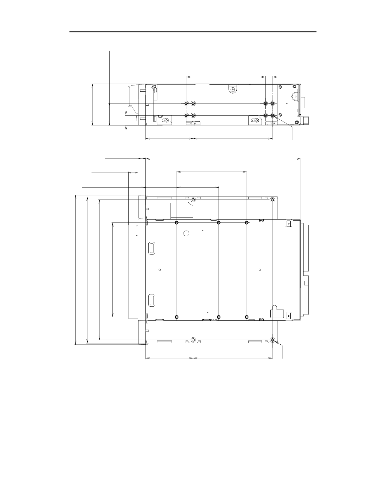
2.1.1.1. Mounting Holes
Figure 2-2a gives details of the mounting holes for the Sony SDX-450V/P and figure 2-2b for the Sony
SDX-450V/RP.
Figure 2-2a: SDX-450V/P Mounting Holes
155.0 0.5mm [6.10" 0.02"]
90.0 0.3mm [3.54" 0.01"]
60.0 0.3mm
[2.36" 0.01"]
70.0 0.3mm [2.76" 0.01"]
31.0 0.3mm
[1.22" 0.01"]
21.0 0.3mm
[0.83" 0.01"]
41.2 0.5mm
[1.62" 0.02"]
4.8 0.5mm
[0.19" 0.02"]
6-M3 (depth 2.5mm [0.10"] max.)
6-M3 (depth 2.5mm [0.10"] max.)
42.0 0.3mm
[1.65" 0.01"]
94.0 0.5mm [3.70" 0.02"]
101.6 0.5mm [4.00" 0.02"]
7.4 0.6mm [0.29" 0.02"]
+
_+
_
+
_+
_
+
_+
_
+
_
+
_
+
_
+
_
+
_
+
_
+
_
+
_
+
_
+
_
+
_
+
_
+
_
+
_
+
_+
_
9.8 0.6mm [0.39" 0.02"]
+
_
+
_+
_
+
_
2.Specification
SONY AIT-1 Turbo drive SDX-450V series Ver.1.0 2-3
Figure 2-2b: SDX-450V/RP Mounting Holes
79.2 0.3mm [3.12" 0.01"]
79.2 0.3mm [3.12" 0.01"]
47.5 0.3mm
[1.87" 0.01"]
79.2 0.3mm [3.12" 0.01"]
47.5 0.3mm
[1.87" 0.01"]
94.0 0.5mm [3.70" 0.02"]
21.8 0.5mm
[0.86" 0.02"]
41.2 0.5mm
[1.62" 0.02"]
9.9 0.5mm
[0.39" 0.02"]
139.6 0.5mm [5.50" 0.02"]
146.0 0.5mm [5.75" 0.02"]
149.0 0.5mm [5.87" 0.02"]
155.0 0.5mm [6.10" 0.02"]
70.0 0.3mm [2.76" 0.01"]
31.0 0.3mm
[1.22" 0.01"] 42.0 0.3mm
[1.65" 0.01"]
4-M3
6-M3
+
_
+
_+
_
+
_
+
_
+
_+
_
+
_
+
_
+
_
+
_+
_
+
_+
_
+
_
+
_+
_
+
_+
_
+
_
+
_
+
_
+
_
+
_
+
_
+
_
+
_+
_
+
_+
_+
_+
_
9.8 0.6mm
[0.39" 0.02"]
+
_+
_
7.4 0.6mm
[0.29" 0.02"]
+
_+
_
7.0 0.5mm
[0.28" 0.02"]
+
_+
_
2.Specification
SONY AIT-1 Turbo drive SDX-450V series Ver.1.0
2-4
2.1.2. Weight
SDX-450V/P 740 grams, without a cassette and a front bezel.
SDX-450V/RP 970 grams, without a cassette and a front bezel.
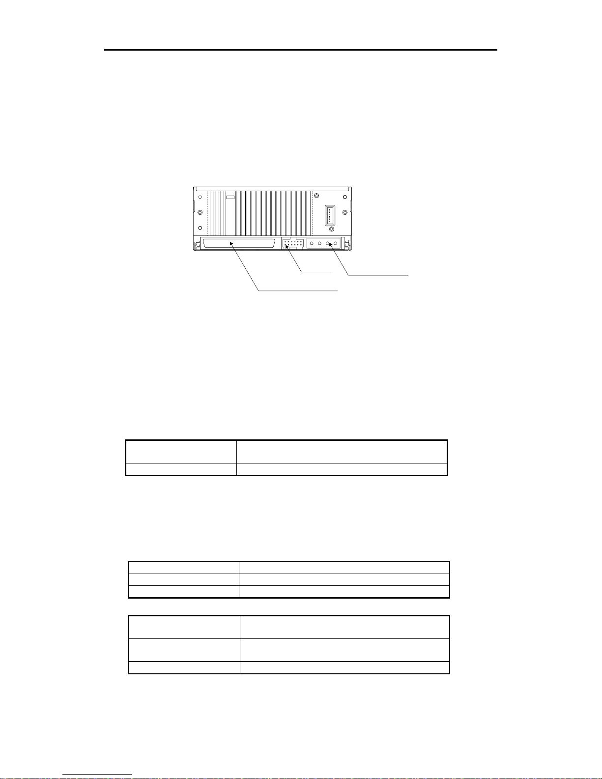
2.1.3. Connectors
TheSDX-450V hasaSCSIconnectorwithapowerconnectorandJumpersatthepositionsshownin Figure2-3.All
other connectors are for use by Sony’s manufacturing and service facilities only.
Figure 2-3: Connector Positions
2.1.3.1. SCSI Cables and Terminators
The Single-Ended SCSI configuration and Low-Voltage-differential SCSI configuration are supported by
SDX-450V/P and SDX-450V/RP. The hardware specification of this interface can be found in Clause 3. Physical
Characteristics, of the X3T10/1142D (SCSI Parallel Interface2) standard. Only unshielded connectors are
supported. Possible cable and connector sources are listed below. This does not imply that these are the only
sources for SCSI accessories.
Note: Whenusinghigh speed datatransfer with theSDX-450V it is recommended that total length of the SCSI data
cable not exceeded 1.5m for Single Ended SCSI configuration. As for Low-Voltage-differential SCSI configuration ,
less than 12m is recommended.
Cable 30 AWG Ribbon
Hitachi UL 20848 (or equivalent)
Connector AMP 1-786090-7 (or equivalent)
2.2. Environmental Specifications
The specifications which apply when media is present may be different than these.
2.2.1. Temperature and Humidity Range
Temperature
Operating 5 ºC to 40 ºC (∆T < 10 ºC/h)
Non-Operating(mech.) -40 ºC to 70 ºC (∆T < 20 ºC/h)
Non-Operating(tape) -40 ºC to 45 ºC (∆T < 20 ºC/h)
Humidity
Operating 20 to 80% RH, non-condensing
Maximum wet bulb temperature : 26 ºC
Non-operating (mech.) 5 to 95%RH(∆RH<30%/h)
Maximum wet bulb temperature : 45 ºC
Non-operating (tape) 20 to 80%RH(∆RH<30%/h)
Jumpers
SCSI 68 pin Connector
Power Connector

2.Specification
SONY AIT-1 Turbo drive SDX-450V series Ver.1.0 2-5
2.2.2. Altitude
Operating 0 to 10,000 feet
2.2.3. Suspended Particulate
Operating Less than 150 microgram/m3
Based Sampling period 24 hours
2.2.4. Vibration
Operating Swept Sine 5 to 500Hz, @0.25G Peak 1 Octave/min.
3 axis, 3 directions
Non-operating Swept Sine 5 to 500Hz, @ 0.5G Peak 1 Octave/min.
3 axis, 3 directions
2.2.5. Shock
Operating No Data Loss
Half Sine
Performance
5 G Peak 3 ms
3 axes, 3 directions
*Interval 10 seconds
Non-operating No Device Damage
Half Sine
90 G Peak 3 ms
(30 G Peak 11 ms)
3 axes, 3 directions
*Interval 10 seconds
2.2.6. Acoustic Noise
The ambient noise level is no greater than 25 dB (A). The sound-meter on (A) scale is located 1m in front of the
center of the drive front panel. (A): A curve weight
Streaming Write/Read 35dB(A)
Insert/Eject 60dB(A)
2.2.7. EMC
EMI/EMS Radiated Emissions /
Conducted noise
Emissions
EN 55022 / 94 + EN 55022 A1 / 95 class B
EMS ESD
(Front Panel Only,
integrated product)
Discharge Voltage
Less than 15kV: No operation failure
Less than 20kV: No drive damage
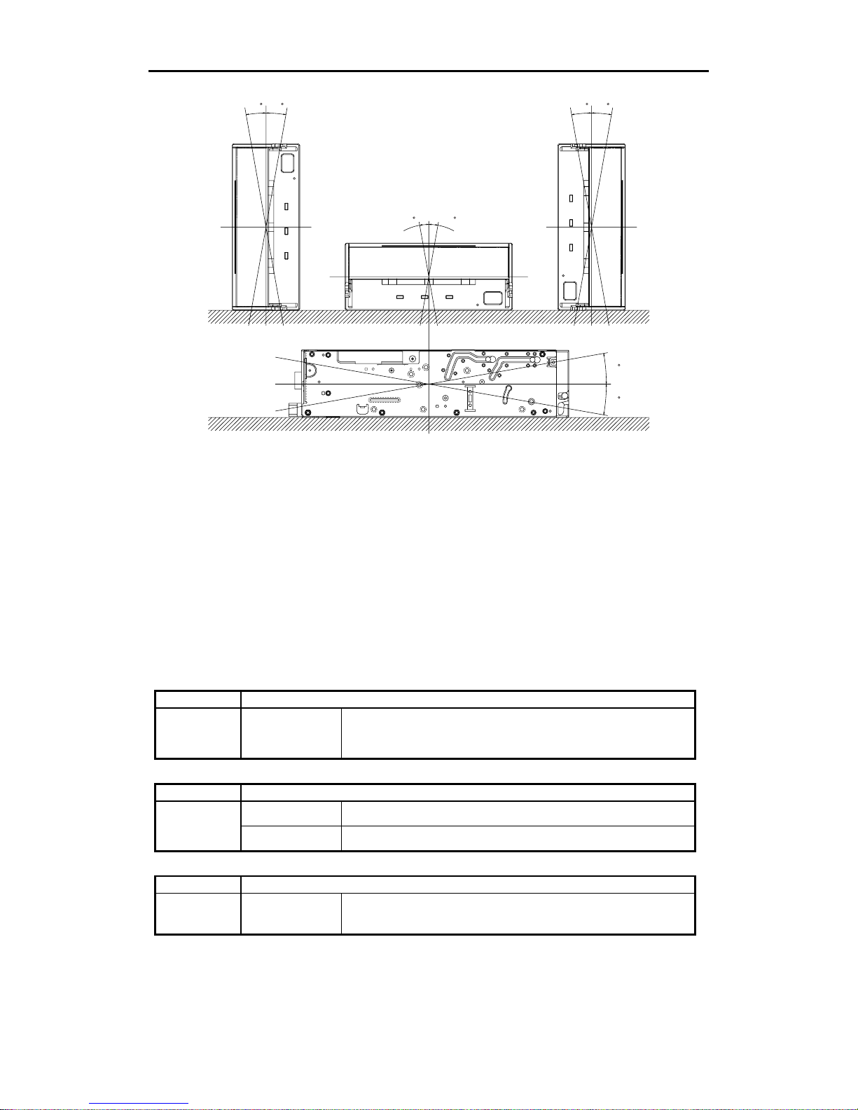
2.2.8. Orientation
TheSDX-450Vcanbeinstalledinthreedifferentmountingpositionsasshowninthefigurebelow. Eachpositionhas
a maximum tolerance of ±10 degrees.
2.Specification
SONY AIT-1 Turbo drive SDX-450V series Ver.1.0
2-6
10 10
10 10
10 10
10
10
Figure 2-4: Mounting Attitude and Tolerance
2.3. Performance Specification
The data capacity, data transfer rate and data reliability specifications this chapter require the media to conform to
the AIT-E Turbo, AIT-1 Turboand AIT-1 Media Specification and also require the drive and media to remain within
their respective operating and non-operating environmental specifications. The specifications below also assume
that the C3 ECC frame is generated on writing and used as necessary on reading, and further assumes that
read-after-write rewrites are used as necessary on writing.
2.3.1. Data Capacity
The SDX-450V includes a data compression capability. When data compression is enabled the drive capacity can
increase from 2 times to 3 times. The efficiency of the data compression depends on the actual data that is being
compressed and cannot be predicted precisely prior to compression.
Format AIT-E Turbo Standard Format
Native
Capacity 20.0 Gbyte typical When using 98 meter tape AIT-E Turbo cassette (TAITE-20N)
Format AIT-1 Standard Format
25.0 Gbyte typical When using 170 meter tape AIT-1 cassette (SDX-T3N and SDX1-25C)
Native
Capacity 35.0 Gbyte typical When using 230 meter tape AIT-1 cassette (SDX1-35C)
Format AIT-1 Turbo Standard Format
Native
Capacity 40.0 Gbyte typical When using 186 meter tape AIT-1 Turbo cassette (TAIT1-40N and
TAIT1-40C)
This manual suits for next models
2
Table of contents
Other Freecom DC Drive manuals


