Use Stage Safety Grade Precautions
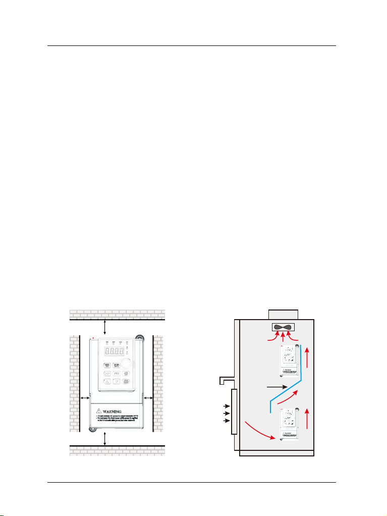
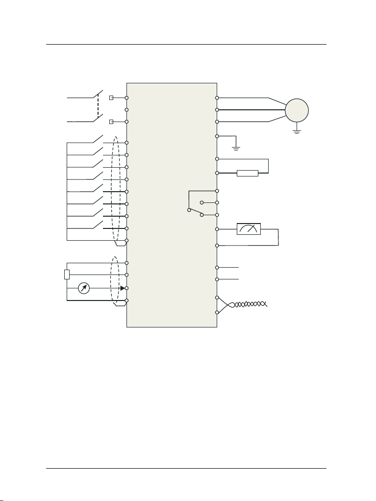
Wiring
²Never connect the power cables to the output terminals
(U,V,W) of the VFD. Pay attention to the marks of the
wiring terminals and ensure correct wiring. Failure to
comply will result in damage to the VFD;
²Install braking resistors at terminals (P+)and (P- or PB)
only. Failure to comply may result in equipment
damage.
²Since all adjustable frequency VFDs from Gozuk have
been subjected to hi-pot test before delivery, users are
prohibited from implementing such a test on this
equipment. Failure to comply may result in equipment
damage.
²Signal wires should to the best of the possibility be
away from main power lines. If this cannot be ensured,
vertical cross-arrangement shall be implemented,
otherwise interference noise to control signal may
occur.
²If motor cables are longer than 100m, it is recommend-
ed output AC reactor be used. Failure to comply may
result in faults.
CAUTION
DANGER
²VFD shall be power-on only after the front cover is
assembled. Risk of electrical hazard.
DANGER
Before
Power-on
²Verify that the input voltage is identical to the rated
voltage of product, correct wiring of input terminals R,S,
T or L1, L2 and output terminals U, V, and W, wiring of
VFD and its peripheral circuits, and all wires should
be in good connection. Risk of VFD damage.
CAUTION
²Do not open the cover after power. Rick of electrical
hazard;
²Do not touches any input/output terminals of VFD with
bare hands. Rick of electrical hazard.
DANGER
After
Power-on ²If auto tuning is required, be careful of personal injury
when motor is running. Risk of accident;
²Do not change the defaults of parameters. Risk of
devices damage.
CAUTION
GK3000 User Manual
-3-