LSIS VFD Quick Start Guide
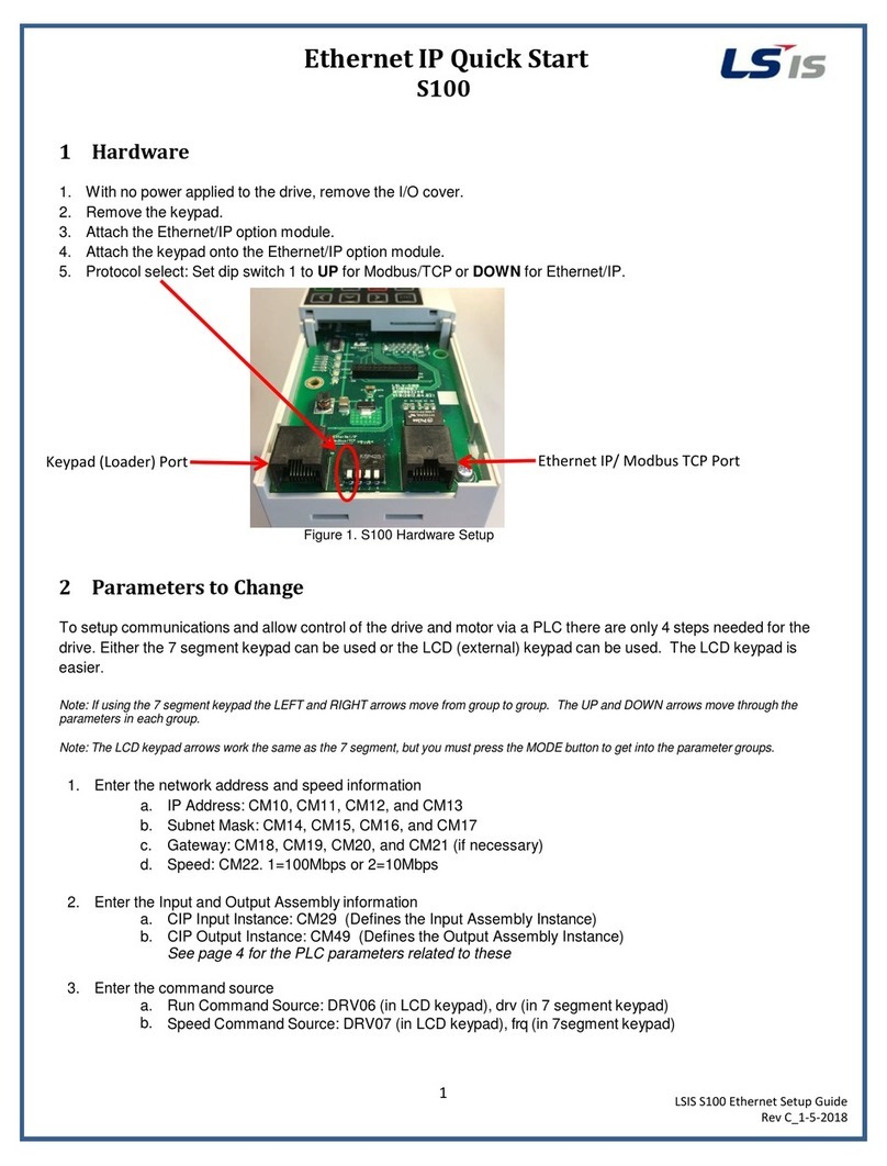
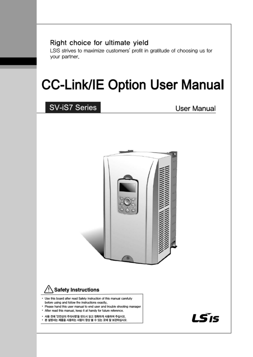
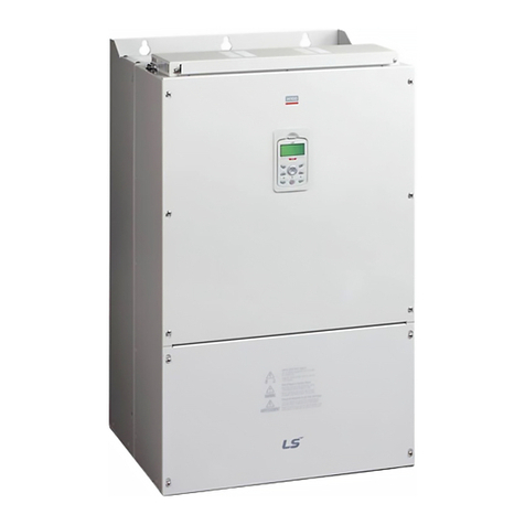
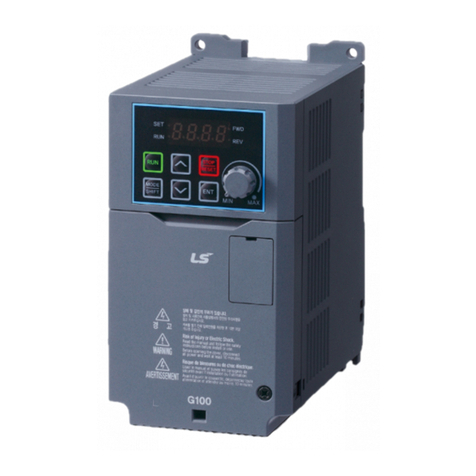
C100, S100, H100, and iS7
2
LSIS VFD Quick Start Guide
Rev G_10-2-2015
By Gary Baase
2. S100/H100/iS7 Basic Setup Parameters
The basic drive and motor parameters are shown in Table 2. Set the parameters according to your application.
Table 2. iS7/H100/S100 Basic Setup Parameters
Note: Many applications will not require changes to the basic setup parameters from their default values.
2.1 S100/H100/iS7 Recommended Additional Parameter Changes
The S100, H100, and iS7 have some default settings the user may want to change to obtain better protection of the
drive/motor and the application. These changes are recommended, but not needed for all applications.
Auto Reset:
Program CON 71 bit 3 to High State (0100).
Program PRT 08 (Reset/Restart after a fault) to “1” (Yes).
Program PRT 09 (Number of Retries) to a number between 0 -10.
Start on Power Loss:
Program ADV 10 (Power on Start) to “1” (Yes).
Phase Loss:
Program PRT 05 (Phase Loss) to the correct bit to the high state for output, input, or both phase loss
recognition. May need to adjust PRT 06 (IPO Band) for input phase loss recognition.
S100 7 segment display: This parameter is in the form of 2 bits. Left bit is 2 (Input), Right bit is bit 1 (Output). It is
represented is in the form of one section of the 7 segment display, ie. | | = low, low; | | = High, igh. High represents
On state, Low represents Off state. H100 and iS7 are shown as dip switches to represent bits.
Group No Group No
Operation 0.00 DRV 1 Command Freq 0 - Max Freq
Operation ACC DRV 3 Acc Time 0 - 6000
Operation dEC DRV 4 Decel Time 1 - 6000
0: Keypad
1: Fx/Rx-1 Start/Stop FW or REV wired separate (P1 = FW, P2 = Rev)
2: Fx/Rx-2 2 Wire Start/Stop (P1 = FW, P2 = Rev)
3: Comm RS485
4: Field Bus
0: Keypad-1
1: Keypad-2 Value Changes immediately
2: V1
4: V2
5: I2
6: Comm RS485
8: Field Bus
12: Pulse
DRV 14 Motor Capacity Depends on drive
BAS 11 Poles 2 - 12
BAS 12 Slip 0 - 3000 RPM If not given then: Rated Freq -((rpm x poles)/120)
BAS 13 Motor Rated Current Depends on drive
BAS 14 No Load Current 0.0 - 1000A
BAS 15 Motor Voltage Depends on drive
BAS 16 Motor Eff % 70 - 100%
BAS 19 Input Voltage 170 - 480V
Set Options
(Use # for 7 Seg)
