Non c o n tra t ual d oc u m ent. W e r e serv e t h e rig h t to i ntr o d u ce m o di f i cat i o n s t hat w e c onsi d e r usef ul , at a n y t i m e.
ITOH DENKI Ju l - 13
- 1 -
UK Branch ITOH DENKI EUROPE S.A.S. Zweigniederlassung Deutschland
Suite 1 Trinity Space Centre 490 av. des Jourdies – Z.A.E. les Jourdies Neumeyerstraße 48
Waldorf Way, Wakefield WF2 8DH – UNITED KINGDOM BP 323 – 74807 – ST PIERRE EN FAUCIGNY Cedex – France 90411 NÜRNBERG - DEUTSCHLAND
Tel: +44 (0)1924 366 539 - Fax : +33 (0)4 50 03 07 60 Tel. : +33 (0)4 50 03 09 99 - Fax : +33 (0)4 50 03 07 60 Tel: +49 911 25 26 200 – Fax : +49 911 25 26 201
SAS au capital de 460 000 Euros - SIRET 343 034 344 000 30 - Code APE 4669B - RCS BONNEVILLE 87 B 413 - N°TVA : FR 71 343034344
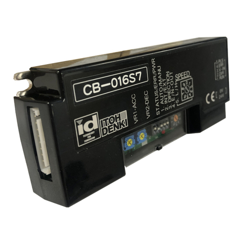
Circuit Board CB016BP-7
Doc/FC/1168-01
Power supply
TBTS 24V DC ± 10% - ripple < 10% - A regulated power supply is recommended
5A built-in fuse - Input current: cf associated Power Moller® 24 specs.
built-in diode for protection against + and - wiring error
Environment
Temperature range 0 / +40 °C / Relative Humidity < 90% - no condensation (prevent thermal shocks)
Non corrosive - non explosive / vibration < 0.5G
CE in accordance with Directive CEM 89/336/CEE
Level of protection
The Circuit Board must be protected from severe shocks and the ingress of water/dust in accordance
with European and local regulations relevant to the installation (UTE C 15-103 :97 ou HD 384.3S2 :95 et
384.5-51S2 :96)
F U N C T I O N
The electronic Circuit Board CB016BP-7 is used to control Power Moller® 24 brushless DC motors with a built-in
electromechanical brake. It is compatible with series PM500FS-B, PM500FS-B, PM500FE-B, PM570FE-B, PM605FE-B. It can only
be used in conjunction with single motors. It performs the following functions:
- Motor Run/Stop
- Selection of the direction of rotation of the motor, depending on the installation requirements
- Variable speed at constant starting torque using an external analogue voltage (0 to 10V)
-Stable speed range in relation to the load
- Dynamic brake and mechanical brake
- Overload protection via built-in thermistor and current limiter
- Error signal in case of motor overload
- PNP or NPN inputs (depending on PLC used) - Factory setting: PNP
- PNP or NPN outputs (depending on PLC used) - Factory setting: PNP
- Acceleration and deceleration regulated using 2 potentiometers (0 – 2sec)
- Motor speed pulse signal output
- Speed selection via rotary switch (20 fixed speeds)
- Automatic or manual restart after overload activation
The Circuit Board delivers a PWM (Pulse Width Modulation) controlled by a magnetic pulse sensor built into the motor
C O N D I T I O N S O F U S E


