Freedom Enterprise MisMatcher Delux User manual

1

2
1. Read these instructions.
2. Keep these instructions.
3. Heed all warnings.
4. Follow all instructions.
5. Do not use apparatus near water - for example, but not limited to: near a bathtub, washbowl, kitchen sink, in a wet
basement, or near a swimming pool or the like.
6. Clean only with dry cloth.
7. Do not install near any heat sources such as radiators, heat registers, stoves or other apparatus (including
ampliers) that produce heat.
8. Protect the power cord from being walked on or pinched particularly at plugs, convenience receptacles, and the
point where they exit from the apparatus.
9. Use attachments/accessories specied by the manufacturer. Ensure that any external equipment used in
conjunction with this product is installed according to the safety specications supplied with that equipment.
10. Unplug this apparatus during lightning storms or when unused for a long period of time.
11. Care should be taken so that objects do not fall and liquids are not spilled into the enclosure through openings. Do
not expose this product to rain or moisture.
12. Refer all servicing to qualied service personnel. Servicing is required when the apparatus has been damaged
in any way, such as if power supply cord or plug is damaged, liquid has been spilled or objects have fallen into the
apparatus, the apparatus has been exposed to rain or moisture, does not operate normally, or has been dropped. ↡
WARNING - When using electric products, these basic precautions should always be followed.

3
Thank you for purchasing the new MisMatcher Delux from Freedom Enterprise.
It has been engineered to be a powerful yet compact and handy tool to help you
throughout your journey to create effects to your heart’s desire. By reading this
manual you’ll become familiar with the MisMatcher Delux, how to use it and how
to make the most of it. Good luck, and have a great experience with your brand-
new video glitcher from Freedom Enterprise.
Thank You.

4
Contents
Cables 5
Quick Start 6
Controls 7
Misc 7
I/O 8
Passive Mixers / Attenuators 9
Enhancer 10
Sync Mixer 11
Principle of Operation 12
Patching Examples 13
1 13
2 14
3 15
4 16
5 17
6 18
7 19
Troubleshooting 20
Specications 21
Warranty 22
5
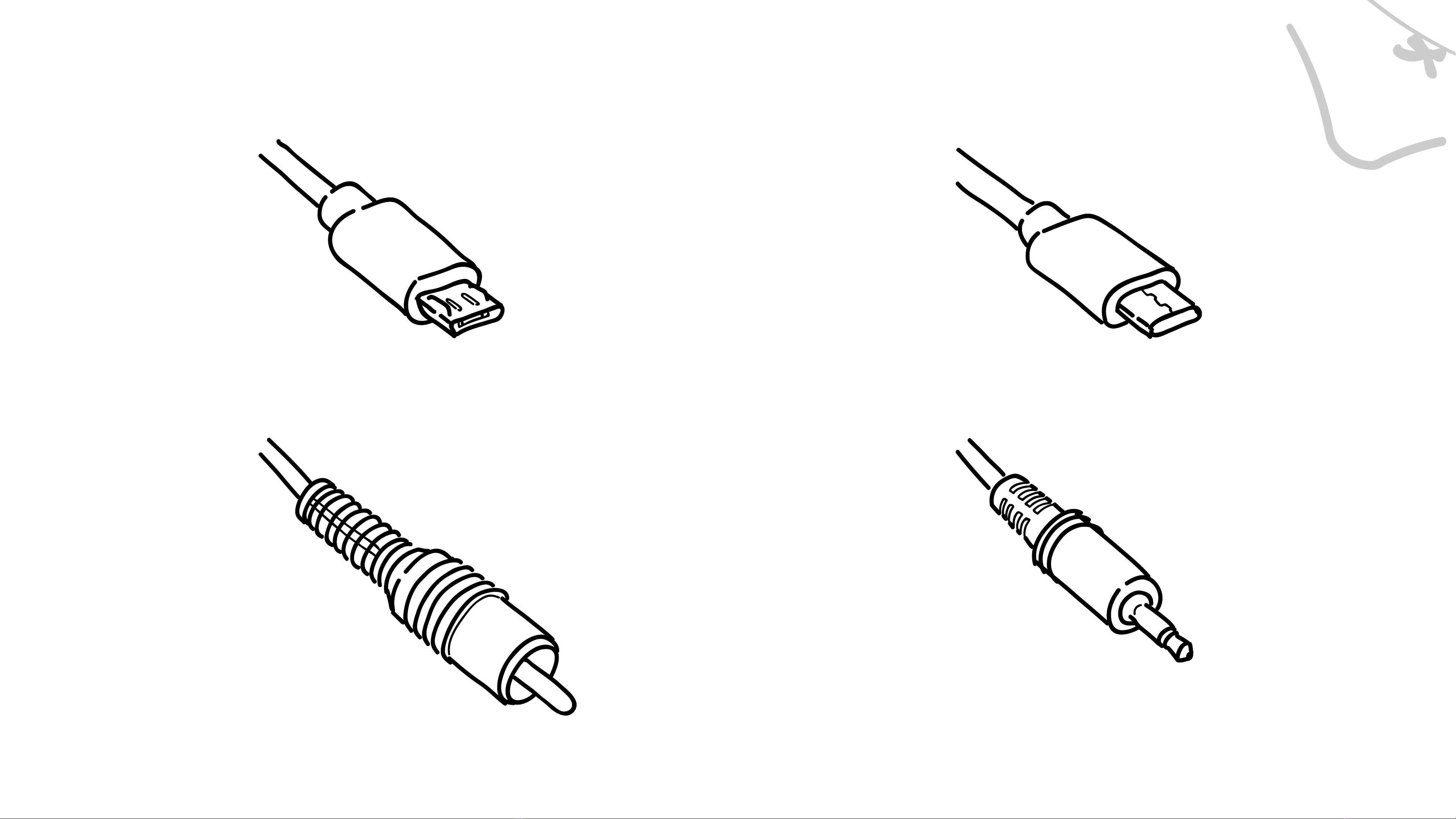
Cables
Micro USB
RCA
Patch Cable (3.5mm
Male to Male)
USB-C

6
Quick Start
1- Connect your Micro USB or Type-C USB cable to a USB charger and then connect it to your MisMatcher Delux.
2- Connect your camera to your MisMatcher’s RCA A port, using a RCA cable
3- Connect your CRT TV to your MisMatcher’s RCA C port, using a RCA cable.
4- Connect one end of a 3.5mm patch cable to the RCA A access point.
5- Connect the other end of the same 3.5mm patch cable to Enhancer In.
6- Connect one end of another 3.5mm patch cable to Enhancer Out.
7- Connect the other end of the same 3.5mm patch cable to the RCA C access point.
8- Use the three knobs at the bottom, Feedback 1, Feedback 2 and Gain to control the effect.

7
Controls
USB Power
Extension Port
For improved reliability and versatility, you can
choose one of two power ports to power your
MisMatcher Deluxe, Micro USB or USB-C.
To connect expansion modules, line up the arrows
near the expansion port in each module and push
them rmly together.
- Misc

8
RCA A RCA B RCA C
RCA A
Patch Point
RCA B
Patch Point
RCA C
Patch Point
The three RCA ports at the top can be used to
easily connect your cameras and monitors to the
MisMatcher Delux. The patch points at the bottom
are used to perform the patching using only 3.5mm
patch cables.
Controls- I/O

9
Potentiometer’s Fixed End
Potentiometer’s Wiper
Potentiometer
The three potentiometers in the user interface can
be used to either attenuate the intensity of a video
signal, or to fade between two different video signals.
The potentiometer’s jacks are automatically
connected to ground if no patch cable is inserted.
Thanks to this you can easily create an attenuator
by connecting your video source to one of the
potentiometer’s xed ends and leaving the other
xed end unplugged. The attenuated signal can be
accessed through the wiper jack in the middle of the
potentiometer.
To fade between two video sources, simply connect
one source to one xed end of the potentiometer
and the other video source to the other xed end.
The wiper will give you the mix between the two.
Controls- Passive Mixers / Attenuators
10
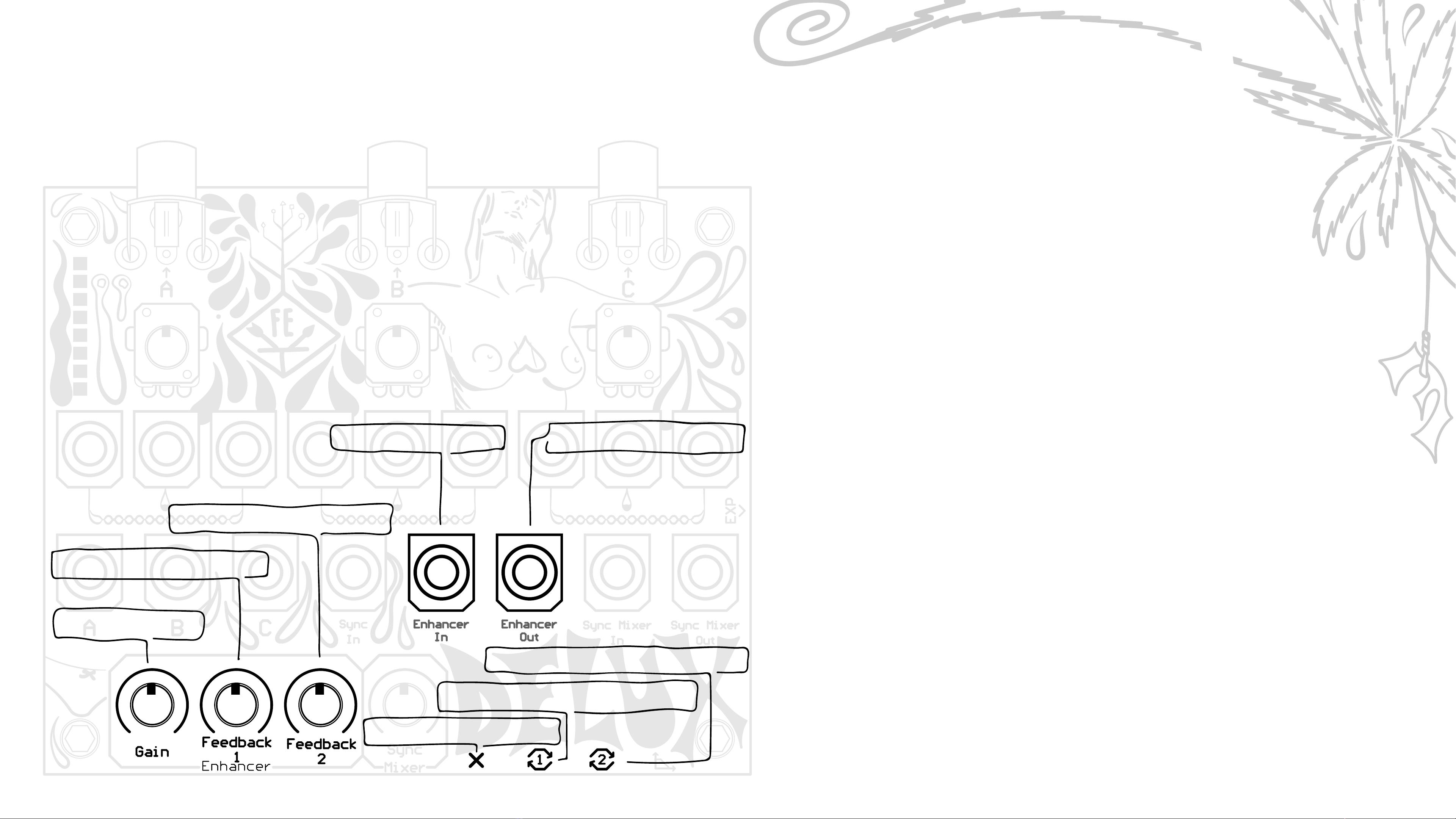
The Enhancer can be used to either boost saturation
and sharpness of the video, or using the provided Gain,
Feedback 1 and 2 controls to distort the video and
create interesting effects. Simply patch some video
into the Enhancer Input and connect your monitor to
Enhancer Output.
The Gain knob controls the overall amplication of
the circuit. It’s normally enabled when nothing is
connected to the Gain Gate Control port, and can be
controlled with an external gate source with a logic
value of 1 to be enabled and 0 to be disabled.
Feedback 1 and Feedback 2 knobs take video from
different stages of the circuit and feeds it back into the
Enhancer’s input. They are normally enabled when
nothing is connected to their respective Feedback 1
Gate Control and Feedback 2 Gate control ports, and
can be controlled with an external gate source with a
logic value of 1 to be enabled and 0 to be disabled.
Controls- Enhancer
Feedback 2 Amount
Gain Gate Control
Feedback 1 Gate Control
Feedback 2 Gate Control
Gain Amount
Feedback 1 Amount
Enhancer Input Enhancer Output
Table of contents
Other Freedom Enterprise Music Pedal manuals


