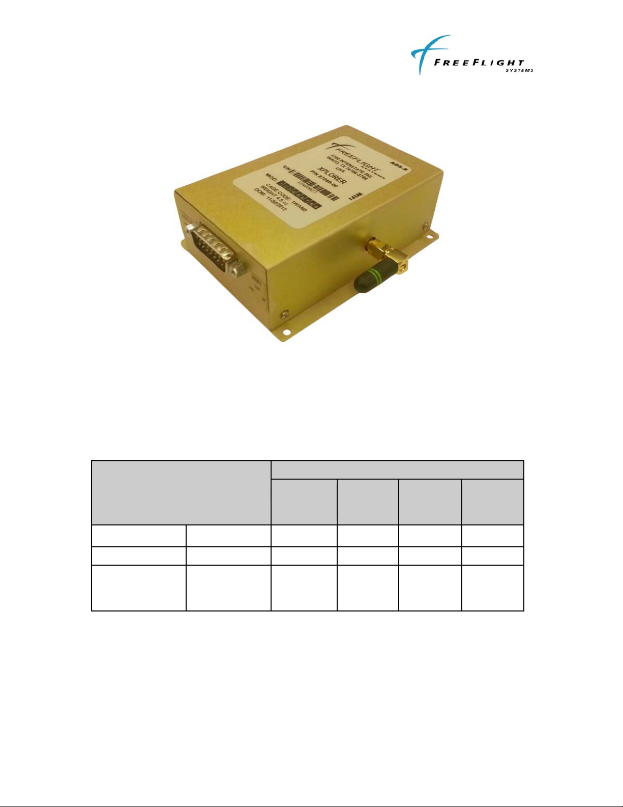
XPLORER ADS-B Receiver
Installation Manual
87214, Revision A December 3, 2012
Table of Contents
SECTION I GENERAL INFORMATION .....................................................................I-1
1.1 INTRODUCTION.............................................................................................I-1
1.2 SYSTEM DESCRIPTION ................................................................................I-1
1.2.1 General Description.....................................................................................I-1
1.2.2 XPLORER CONFIGURATIONS..................................................................I-1
1.2.3 Example Configurations ..............................................................................I-2
1.2.4 GPS Usage..................................................................................................I-3
1.3 XPLORER INSTALLATION OVERVIEW ........................................................I-4
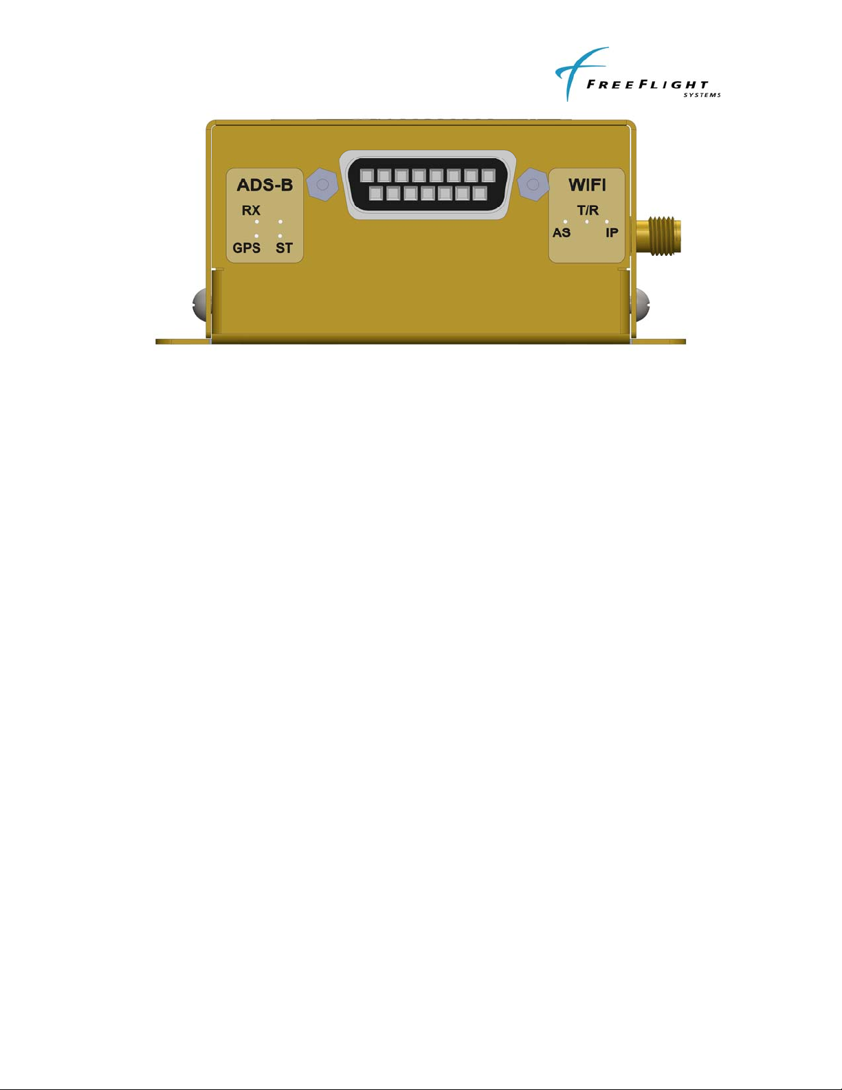
1.3.1 Connectors ..................................................................................................I-4
1.3.2 Status Lights................................................................................................I-4
1.4 UAT ANTENNA REQUIREMENTS .................................................................I-5
1.5 Technical Characteristics ................................................................................I-6
1.6 PARTS AND EQUIPMENT .............................................................................I-7
1.6.1 XPLORER Receiver Items ..........................................................................I-7
1.6.2 Installation Kits ............................................................................................I-7
1.7 MATERIALS REQUIRED BUT NOT SUPPLIED.............................................I-8
1.7.1 Required......................................................................................................I-8
1.7.2 Optional .......................................................................................................I-8
SECTION II INSTALLATION ......................................................................................II-1
2.1 GENERAL ......................................................................................................II-1
2.2 UNPACKING AND INSPECTING EQUIPMENT ............................................II-1
2.3 EQUIPMENT MOUNTING .............................................................................II-1
2.3.1 XPLORER Mounting...................................................................................II-1
2.4 COOLING REQUIREMENTS .........................................................................II-1
2.5 XPLORER ELECTRICAL CONNECTIONS ...................................................II-2
2.5.1 XPLORER INTERFACE – PINOUT ...........................................................II-2
2.6 XPLORER INTERFACE DETAILS.................................................................II-2
2.6.1 Power Input ................................................................................................II-2
2.6.2 Serial Interfaces (RS-232 Version Only) ....................................................II-2
2.6.3 Time Mark Input (PPS) ...............................................................................II-3
2.6.4 Maintenance Interface (RS-232 Version Only)...........................................II-3
2.6.5 Status LEDs................................................................................................II-3
2.7 UAT ANTENNA INSTALLATION ...................................................................II-4