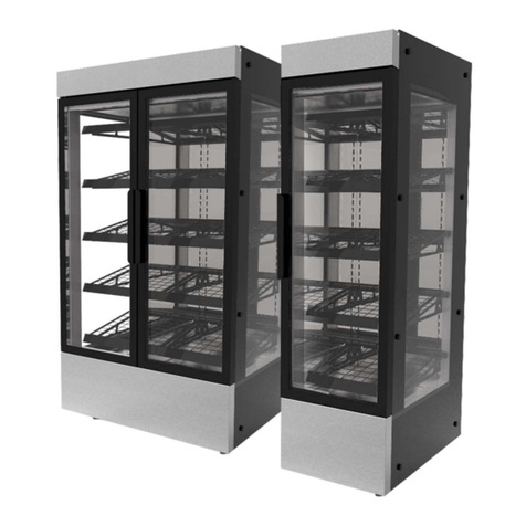
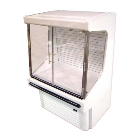
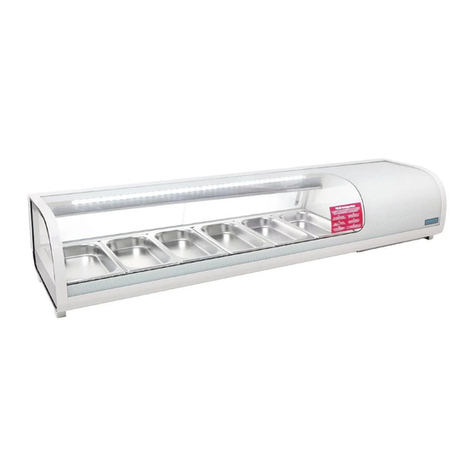
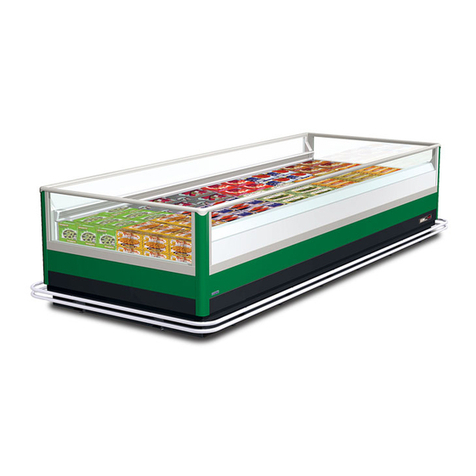
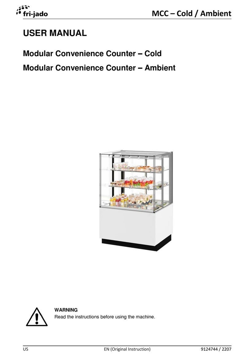
Fri-Jado MC 75 User manual

Service Manual Modular Counter Hot and Cold form 9123791 rev.03/2017
WWW.FRIJADO.COM
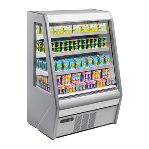
Models:
MC 75 and 100 Hot Full Service. Curved and Square glass
MC 75 and100 Hot Self Service. Curved and Square glass
MC 75 and100 Cold Full Service. Curved and Square glass
MC 75 and100 Cold Self Service. Curved and Square glass
Curved and Cube underframe
SERVICE MANUAL
MODULAR COUNTER HOT AND COLD MERCHANDSERS
- NOTICE -
This manual is prepared for the use of trained Service Technicians and
should not be used by those not properly qualified. If you have atten-
ded a trianing for this product, you may be qualified to perform all the
procedures in this manual.
This manual is not intended to be all encompassing. If you have not
attended training for this product, you should read, in its entirety, the
repair procedure you wish to perform to determine if you have the ne-
cessary tools, instruments and skills required to perform the procedure.
Procedures for which you do not have the necessary tools, instruments
and skills should be performed by a trained technician.
Reproduction or other use of this Manual, without the express written
consent of Fri-Jado, is prohibited.
Curved glass Square glass

Service Manual Modular Counter Hot and Cold form 9123791 rev.03/2017Page 2

Service Manual Modular Counter Hot and Cold form 9123791 rev.03/2017 Page 3
Versions
Version Issue date
dd/mm/yy
Remarks
01/2010 01/01/2010 First release.
12/2014 01/12/2014 Model MC 100 updated. Model MC 75 added. Various updates.
03/2017 01/03/2017 New ERC 211 and 213 thermostat added. Square models added.
New electric diagrams. Various updates.

Page 4 Service Manual Modular Counter Hot and Cold form 9123791 rev.03/2017
INDEX
Index .......................................................................................................................................................... 4
General technical data.............................................................................................................................. 6
Removal and replacement of parts in hot version ................................................................................ 8
Side Panels.............................................................................................................................................. 8
Front Panel............................................................................................................................................. 8
Sliding wheel on door ........................................................................................................................... 9
Thermostat (Danfoss ERC 211) .............................................................................................................. 9
Sensor Danfoss thermostat ................................................................................................................ 10
Tumble switch light and heating ........................................................................................................ 10
Top Shelves........................................................................................................................................... 11
Bottom Shelf ........................................................................................................................................ 11
Lamp holder......................................................................................................................................... 12
Electronic ballast.................................................................................................................................. 12
Curved glass self service and flat glass Square .................................................................................. 13
Safety thermostat (MC 100 Hot self service) ...................................................................................... 13
Heating element in top (MC 100 Hot self service)............................................................................. 14
Blower (self service)............................................................................................................................. 14
Removal and replacement of parts in cold version ............................................................................. 15
Side panels ........................................................................................................................................... 15
Front panel........................................................................................................................................... 15
Sliding wheel on door ......................................................................................................................... 16
Thermostat (Danfoss ERC 213) ............................................................................................................ 16
Temperature sensor ............................................................................................................................. 17
Defrost sensor ...................................................................................................................................... 18
Tumble switch light and cooling......................................................................................................... 19
Lamp holder......................................................................................................................................... 19
Relay ..................................................................................................................................................... 20
Electronic ballast.................................................................................................................................. 20
Curved glass self service and flat glass Square................................................................................... 21
Blower(S) ............................................................................................................................................. 21
Changing Danfoss EKC to ERC thermostat........................................................................................ 22
Electrical tests and service procedures hot version.............................................................................. 24
Heating element test........................................................................................................................... 24
TL lamp test.......................................................................................................................................... 24
Contactor and blower test .................................................................................................................. 25
Adjusting Danfoss ERC 211 thermostat.............................................................................................. 26
Adjusting Danfoss ERC 211 thermostat (continued) ......................................................................... 27
Error codes ERC 211............................................................................................................................. 27
Danfoss ERC 211 settings MC 75 + 100 full service ............................................................................ 28
Danfoss ERC 211 settings MC 75 + 100 self Service ........................................................................... 29
Adjusting Danfoss EKC 102A thermostat till serial number 100080879........................................... 30
Adjusting Danfoss EKC 102A thermostat till serial number 100080879........................................... 31
Control locations full and self service hot.......................................................................................... 32

Service Manual Modular Counter Hot and Cold form 9123791 rev.03/2017 Page 5
Electrical tests and service procedures cold version............................................................................. 33
Heating element test Evaporation tray.............................................................................................. 33
TL lamp test.......................................................................................................................................... 33
Adjusting Danfoss ERC 213 thermostat.............................................................................................. 34
Adjusting Danfoss ERC 213 thermostat (continued) ......................................................................... 35
Error codes ERC 213............................................................................................................................. 35
Danfoss ERC 213 settings MC 75 + 100 full service ............................................................................ 36
Danfoss ERC 213 settings MC 75 self service ...................................................................................... 37
Danfoss ERC 213 settings MC 100 self service .................................................................................... 38
Adjusting Danfoss EKC 102C thermostat till serial number 100080879 .......................................... 39
Adjusting Danfoss EKC 102C thermostat till serial number 100080879 .......................................... 40
Adjusting Danfoss EKC 102C thermostat till serial number 100080879 .......................................... 41
Control locations full and self serve cold ........................................................................................... 42
Troubleshooting ...................................................................................................................................... 43
Troubleshooting Modular Counter 75 and 100 Hot .......................................................................... 43
Analytic troubleshooting Modular Counter 75 and 100 Hot............................................................ 44
Troubleshooting Modular Counter 75 and 100 Cold......................................................................... 45
Analytic troubleshooting Modular Counter 75 and 100 Cold .......................................................... 46
Exploded views & Part lists.................................................................................................................... 48
Modular counter 75 Hot full service (Cube, Square) ......................................................................... 48
Modular counter 75 Hot self service (Cube, Square) ......................................................................... 50
Modular counter 75 Hot full service (Cube, Curved) ......................................................................... 52
Modular counter 75 Hot self service (Cube, Curved)......................................................................... 54
Modular counter 75 Cold full service (Cube, Square)........................................................................ 56
Modular counter 75 Cold self service (Cube, Square)........................................................................ 60
Modular counter 75 Cold full service (Cube, Curved)........................................................................ 62
Modular counter 75 Cold self service (Cube, Curved) ....................................................................... 64
Modular counter 100 Hot full service (Cube, Square) ....................................................................... 68
Modular counter 100 Hot self service (Cube, Square) ....................................................................... 70
Modular counter 100 Hot full service (Cube, Curved) ....................................................................... 72
Modular counter 100 Hot full service (Curved, Curved).................................................................... 74
Modular counter 100 Hot self service (Cube, Curved)....................................................................... 76
Modular counter 100 Hot self service (Curved, Curved).................................................................... 78
Modular counter 100 Cold full service (Cube, square) ...................................................................... 80
Modular counter 100 Cold self service (Cube, square) ...................................................................... 84
Modular counter 100 Cold full service (Cube, Curved)...................................................................... 88
Modular counter 100 Cold full service (Curved, Curved) .................................................................. 90
Modular counter 100 Cold self service (Cube, Curved) ..................................................................... 94
Modular counter 100 Cold self service (curved, Curved)................................................................... 98
Electrical diagrams................................................................................................................................ 102
Circuit Diagram MC 75 -100 Hot full and self service ...................................................................... 102
Circuit Diagram MC 75 -100 Hot full and self service till serial nr. 100080879............................... 103
Circuit Diagram MC 75 -100 Cold full and self service..................................................................... 104
Circuit Diagram MC 75 -100 Cold full and self service till serial nr. 100080879 ............................. 105
Page 6 Service Manual Modular Counter Hot and Cold form 9123791 rev.03/2017
GENERAL TECHNICAL DATA
This manual covers the Modular Counter Hot and Cold Merchandisers. The Merchandisers come
in 4 versions and 2 sizes of 750 and 1000 mm.
• MC 75 and100 Hot Full Service.
• MC 75 and100 Hot Self Service.
• MC 75 and 100 Cold Full Service.
• MC 75 and 100 Cold Self Service.
All of the information, illustrations and specifications contained in this manual are based on the
latest product information available at the time of printing.
Type MC 75 Hot
Full Service
MC 75 Hot
Self Service
MC 75 Cold
Full Service
MC 75 Cold
Self Service
Power (W) 2800 2900 1300 1300
Fuses needed with power connection
230V, 1N ~ 50Hz ( 1 phase with zero ) 1x 16 A 1x 16 A 1x 10 A 1x 10 A
Standard plug from factory single
pole
Two-pole
earthed plug
16 A
Two-pole
earthed plug
16 A
Two-pole
earthed plug
16 A
Two-pole
earthed plug
16 A
Sound pressure - - < 70 dB(A) < 70 dB(A)
Temp. class Full and Self service* - - 3M2 3M2
Net weight (kg) 161 156 161 163
Gross weight (kg) 188 182 188 190
Height (mm) 1516 1516 1516 1516
Width (mm) 750 750 750 750
Depth (mm) 771 771 771 771
Maximum loading height 10 cm 10 cm
Temperature class* - - 3M2 3M2
Refrigerant** - - R134A R134A
Amount of refrigerant - - 0.450 kg 0.450 kg
* Product temperature class according to NEN-EN 441-6
** The refrigerant complies with the environmental requirements applicable at the time of manufacturing of
the unit.
Tools
• Standard set of tools.
• Metric wrenches, sockets and hex socket key wrenches.
• Multi-meter and AC current clamp meter.
• Insulation value tester (Megger)
• Temperature tester.
TECHNICAL DATA
GENERAL TECHNICAL DATA

Page 7
Service Manual Modular Counter Hot and Cold form 9123791 rev.03/2017
GENERAL TECHNICAL DATA
Type MC 100 Hot
Full Service
MC 100 Hot
Self Service
MC 100 Cold
Full Service
MC 100 Cold
Self Service
Power (W) 2800 3000 1300 1300
Fuses needed with power connection
230V, 1N ~ 50Hz ( 1 phase with zero ) 1x 16 A 1x 16 A 1x 10 A 1x 10 A
Standard plug from factory single
pole
Two-pole
earthed plug
16 A
Two-pole
earthed plug
16 A
Two-pole
earthed plug
16 A
Two-pole
earthed plug
16 A
Sound pressure - - < 70 dB(A) < 70 dB(A)
Temp. class Full and Self service* - - 3M2 3M2
Net weight (kg) 180 175 190 185
Gross weight (kg) 212 206 224 218
Height (mm) 1516 1516 1516 1516
Width (mm) 1000 1000 1000 1000
Depth (mm) 771 771 771 771
Maximum loading height 10 cm 10 cm
Temperature class* - - 3M2 3M2
Refrigerant** - - R134A R134A
Amount of refrigerant - - 0.580 kg 0.580 kg
* Product temperature class according to NEN-EN 441-6
** The refrigerant complies with the environmental requirements applicable at the time of manufacturing of
the unit.
Tools
• Standard set of tools.
• Metric wrenches, sockets and hex socket key wrenches.
• Multi-meter and AC current clamp meter.
• Insulation value tester (Megger)
• Temperature tester.
TECHNICAL DATA

Page 8 Service Manual Modular Counter Hot and Cold form 9123791 rev.03/2017
REMOVAL AND REPLACEMENT OF PARTS
WARNING: Disconnect the electrical power to the machine
at the main circuit box. Place a tag on the circuit box indica-
ting the circuit is being serviced.
1. Remove the 3 screws on the backside that
hold the panel.
2. Slide the side panel backwards and remo-
ve the panel.
3. Reverse the procedure to install.
Note: When placing the plate back lift the
plate against the top side and pull the plate
on the bottom side to guide it past the side.
1. Loosen the 2 screws on the bottom front-
side.
2. Remove the 2 screws on the top side and
remove the panel.
3. Reverse the procedure to install.
Note: When placing the front back see to it
that it fits over the side panels.
REMOVAL AND REPLACEMENT OF PARTS IN HOT VERSION
SIDE PANELS
FRONT PANEL

Page 9
Service Manual Modular Counter Hot and Cold form 9123791 rev.03/2017
REMOVAL AND REPLACEMENT OF PARTS
1. Remove the door by lifting this out of the
runner and bring it towards yourself.
2. Use a drill of 4.2 mm to drill out the 2
pop rivets.
3. Fix the new wheel again with pop rivets
of 4.2 mm.
4. Place the door back again.
SLIDING WHEEL ON DOOR
THERMOSTAT (DANFOSS ERC 211)
1. Remove the 3 screws that secure the ope-
ration panel and open the panel.
2. Loosen the blocking clips on the sides of
the thermostat and remove thermostat
from housing.
4. Remove the wiring from the thermostat.
5. Reverse the procedure to install.
Old version with
separate handles
New version with
integrated handles

Page 10 Service Manual Modular Counter Hot and Cold form 9123791 rev.03/2017
REMOVAL AND REPLACEMENT OF PARTS
1. Open the operation panel according prior
procedure.
2. Remove the wiring of the sensor on the
thermostat.
3. Remove the front glass and both side
glasses.
5. Remove the screws that secure the cover
profile on the left backside and remove
the profile.
6. Remove the screws that secure the top
shelf on both sides on the shelf support.
7. Slide the top shelf carefully for 10 cm. to
the customer side.
8. Remove the screws that secure the sensor
holder and remove the sensor from the
holder.
9. Lead the wiring of the sensor to the front
and remove the wiring.
10.Reverse the procedure to install.
Note: See to it that the sensor is placed
straight inside the shelf.
SENSOR DANFOSS THERMOSTAT
TUMBLE SWITCH LIGHT AND HEATING
1. Open the operation panel according prior
procedure.
2. Disconnect the wiring.
3. Remove the switch by pushing the clamps
on both sides.
4. Reverse the procedure to install.

Page 11
Service Manual Modular Counter Hot and Cold form 9123791 rev.03/2017
REMOVAL AND REPLACEMENT OF PARTS
1. Remove the front panel, operation panel,
side and front glass according prior proce-
dures.
2. Remove the screws that secure the cover
profile on the right hand backside and
remove the profile.
3. Remove the screws that secure the shelf
on both sides on the shelf support. For
top shelve remove the sensor according
prior procedure.
4. Remove the screws that secure the cover
on the electric box and lower the cover.
5. Disconnect the wiring of the heating ele-
ment.
6. Remove the shelf by sliding it to the front
side and guide the wiring outside.
7. Remove the price rail and holder from the
shelf.
8. Reverse the procedure to install.
TOP SHELVES
BOTTOM SHELF
1. Remove the front panel, side and front
glass and the gastronorm trays according
prior procedures.
2. Remove the screws that secure the shelf on
the backside.
3. Remove the screws that secure the cover
on the electric box and lower the cover.
4. Disconnect the wiring of the heating ele-
ment.
5. Remove the shelf by lifting it out of the
bottom side and guide the wiring outside.
6. Remove the price rail and holder from the
shelf.
7. Reverse the procedure to install.

Page 12 Service Manual Modular Counter Hot and Cold form 9123791 rev.03/2017
REMOVAL AND REPLACEMENT OF PARTS
LAMP HOLDER
1. Remove the front glass (only full service)
and the lamp.
2. Remove the holder out of the clipped
fixation and pull the wiring outside for
about 5 cm.
3. Disconnect the wiring by turning and pul-
ling of the wire.
4. Reverse the procedure to install.
ELECTRONIC BALLAST
1. Remove the front panel according prior
procedure.
2. Remove the screws that secure the cover
on the electric box and lower the cover.
3. Remove the wiring from the Ballast.
4. Remove the screws that secure the ballast
and remove the ballast.
5. Reverse the procedure to install.

Page 13
Service Manual Modular Counter Hot and Cold form 9123791 rev.03/2017
REMOVAL AND REPLACEMENT OF PARTS
1. Turn the curved or flat glass to the top
position.
2. Remove the cover plates on the mounting
profile (if necessary).
3. Loosen the adjusting screws that secure
the glass with the a torques key TX15.
4. Remove the glass.
5. Place the new glass with the plastic pro-
tection profile.
6. Reverse the procedure to install.
CURVED GLASS SELF SERVICE AND FLAT GLASS SQUARE
1. Remove the screws that secure the cover
profile on the left backside and remove
the profile.
2. Remove, on the top side, the screws that
secure the light fixture and turn the light
fixture downwards.
3. Remove the sensor from the clip and lead
the sensor outside.
4. Remove the screws that secure the ther-
mostat and remove the thermostat.
5. Remove the wiring from the thermostat.
6. Reverse the procedure to install.
Note: Set the thermostat on 175°C.
SAFETY THERMOSTAT (MC 100 HOT SELF SERVICE)

Page 14 Service Manual Modular Counter Hot and Cold form 9123791 rev.03/2017
REMOVAL AND REPLACEMENT OF PARTS
HEATING ELEMENT IN TOP (MC 100 HOT SELF SERVICE)
1. Remove the side glass and the cover pro-
file on the left and right hand side on the
backside according prior procedures.
2. Remove, on the top side, the screws that
secure the light fixture and turn the light
fixture downwards.
3. Slide the insulation sleeve backwards on
both sides of the element en remove the
wiring.
4. Remove the nuts on both ends on the he-
ating element and remove the element.
5. Reverse the procedure to install.
Note: Don’t forget to put the sleeves back on
there places.
BLOWER (SELF SERVICE)
1. Remove the front panel according prior
procedure.
2. Remove the bolts that secure the moun-
ting plate of the blower assembly and
move the assembly towards yourselves.
3. Remove the wiring from the blower.
4. Remove the screws that secure the cover
plate on the blower housing and remove
the plate.
5. Remove the screws that secure the blo-
wer and remove the blower.
6. Remove the screws that secure the tube
with flange and remove the flange.
7. Reverse the procedure to install.
Note: See to it that the steel tubes of the
blower are fitted back again inside the PVC
tubing.

Page 15
Service Manual Modular Counter Hot and Cold form 9123791 rev.03/2017
REMOVAL AND REPLACEMENT OF PARTS
WARNING: Disconnect the electrical power to the machine
at the main circuit box. Place a tag on the circuit box indica-
ting the circuit is being serviced.
1. Remove the 3 screws on the backside that
hold the panel.
2. Slide the side panel backwards and remo-
ve the panel.
3. Reverse the procedure to install.
Note: When placing the plate back lift the
plate against the top side and pull the plate
on the bottom side to guide it past the side.
1. Loosen the 2 screws on the bottom front-
side.
2. Remove the 2 screws on the top side and
remove the panel.
3. Reverse the procedure to install.
Note: When placing the front back see to it
that it fits over the side panels.
REMOVAL AND REPLACEMENT OF PARTS IN COLD VERSION
SIDE PANELS
FRONT PANEL

Page 16 Service Manual Modular Counter Hot and Cold form 9123791 rev.03/2017
REMOVAL AND REPLACEMENT OF PARTS
1. Remove the door by lifting this out of the
runner and bring it towards yourself.
2. Use a drill of 4.2 mm to drill out the 2
pop rivets.
3. Fix the new wheel again with pop rivets
of 4.2 mm.
4. Place the door back again.
SLIDING WHEEL ON DOOR
THERMOSTAT (DANFOSS ERC 213)
1. Remove the 3 screws that secure the cover
panel and remove the panel.
2. Remove the 2 screws that secure the ope-
ration panel and remove the panel.
3. Loosen the blocking clips on the sides of
the thermostat and remove thermostat
from housing.
4. Remove the wiring from the thermostat.
5. Reverse the procedure to install.
Old version with
separate handles
New version with
integrated handles

Page 17
Service Manual Modular Counter Hot and Cold form 9123791 rev.03/2017
REMOVAL AND REPLACEMENT OF PARTS
1. (Full service only) Remove the front glass.
2. Remove the suction grid and the 2 flat
plates on the bottom side inside the cabi-
net.
3. Remove the 2 screws that secure the blo-
wer plate and turn the blower plate.
5. Cut the tyrap that holds the sensor and
remove the sensor.
6. Remove the operation panel according
prior procedure and disconnect the wiring
of the sensor on the thermostat.
7. Remove the sensor.
8. Reverse the procedure to install.
Note 1: When refitting the sensor it is easiest
to guide the wiring of the sensor through
the hole starting on the bottom side.
Note 2: The sensor wiring will pass through
the polyurethane foam. When installing the
new sensor some extra sealant should be ap-
plied to recreate a watertight fit.
TEMPERATURE SENSOR
Full service
older model
1 blower
Full and
Self service
2 blowers

Page 18 Service Manual Modular Counter Hot and Cold form 9123791 rev.03/2017
REMOVAL AND REPLACEMENT OF PARTS
DEFROST SENSOR
1. Remove the front glass (full service only),
suction grid, the 2 flat plates, blower
plate and operation panel according prior
procedures.
2. Lift out the holder with the honeycomb
profile.
3. Measure the distance and place where the
sensor is placed inside the evaporator.
Remove the sensor from between the seg-
ments of the evaporator.
4. Disconnect the wiring on the thermostat
and remove the sensor.
5. Reverse the procedure to install.
Note 1: When refitting the sensor it is easiest
to guide the wiring of the sensor through
the hole starting on the bottom side.
Note 2: The sensor wiring will pass through
the polyurethane foam. When installing the
new sensor some extra sealant should be ap-
plied to recreate a watertight fit.
Full service
older model
1 blower
Full and
Self service
2 blowers

Page 19
Service Manual Modular Counter Hot and Cold form 9123791 rev.03/2017
REMOVAL AND REPLACEMENT OF PARTS
LAMP HOLDER
1. Remove the front glass (only full service)
and the lamp.
2. Remove the holder out of the clipped
fixation and pull the wiring outside for
about 5 cm.
3. Disconnect the wiring by turning and pul-
ling of the wire.
4. Reverse the procedure to install.
TUMBLE SWITCH LIGHT AND COOLING
1. Open the operation panel according prior
procedure.
2. Disconnect the wiring.
3. Remove the switch by pushing the clamps
on both sides.
4. Reverse the procedure to install.

Page 20 Service Manual Modular Counter Hot and Cold form 9123791 rev.03/2017
REMOVAL AND REPLACEMENT OF PARTS
RELAY
ELECTRONIC BALLAST
1. Remove the cover panel according prior
procedure.
2. Remove the screw that secures the venti-
lation backpanel and remove the panel.
3. Remove the screws that secure the cover
on the electric box and lower the cover.
3. Remove the wiring from the relay.
4. Remove the screws that secure the relay
and remove the relay.
5. Reverse the procedure to install.
1. Remove the cover panel and the ventilati-
on back panel according prior procedures.
2. Remove the screws that secure the cover
on the electric box and lower the cover.
3. Remove the wiring from the ballast.
4. Remove the screws that secure the ballast
and remove the ballast.
5. Reverse the procedure to install.
This manual suits for next models
9
Table of contents
Other Fri-Jado Display Case manuals