Fri-Jado Turbo Deli Rotisserie TDR 5m User manual

WWW.FRIJADO.COM
Service Manual Turbo Deli RotisserieII form 9120929 rev. 04/2021
Turbo Deli Rotisserie
- NOTICE -
This manual is prepared for the use of trained Service Technicians and should
not be used by those not properly qualified. If you have attended a training
for this product, you may be qualified to perform all the procedures in this
manual.
This manual is not intended to be all encompassing. If you have not attended a
training for this product, you should read, in its entirety, the repair procedure
you wish to perform to determine if you have the necessary tools, instru-
ments and skills required to perform the procedure. Procedures for which you
do not have the necessary tools, instruments and skills should be performed
by a trained technician.
Reproduction or other use of this Manual, without the express written consent of
Fri-Jado, is prohibited.
SERVICE MANUAL
MODELS
TDR 5m
TDR 5p
TDR 8 m
TDR 8 p/i
Model TDR 8 p

Page 2 Service Manual Turbo Deli RotisseriePKII form 9120929 rev. 04/2021
EMPTY PAGEEMPTY PAGE

Page 3
Service Manual Turbo Deli RotisserieII form 9120929 rev. 04/2021
Versions
Version Issue date
dd/mm/yy
Remarks
2020 Merging of previous manuals from TDR m, TDR p and TDR i.
Addition of TDRp with 9192400 pcb board
20210430 30-04-2021 First release

INDEX
Page 4
TABLE OF CONTENTS
Service Manual Turbo Deli RotisseriePKII form 9120929 rev. 04/2021
Index .......................................................................................................................................................... 4
General technical data.............................................................................................................................. 6
Technical Data ....................................................................................................................................... 6
Programming instructions TDR p............................................................................................................. 7
Connecting mains power ...................................................................................................................... 7
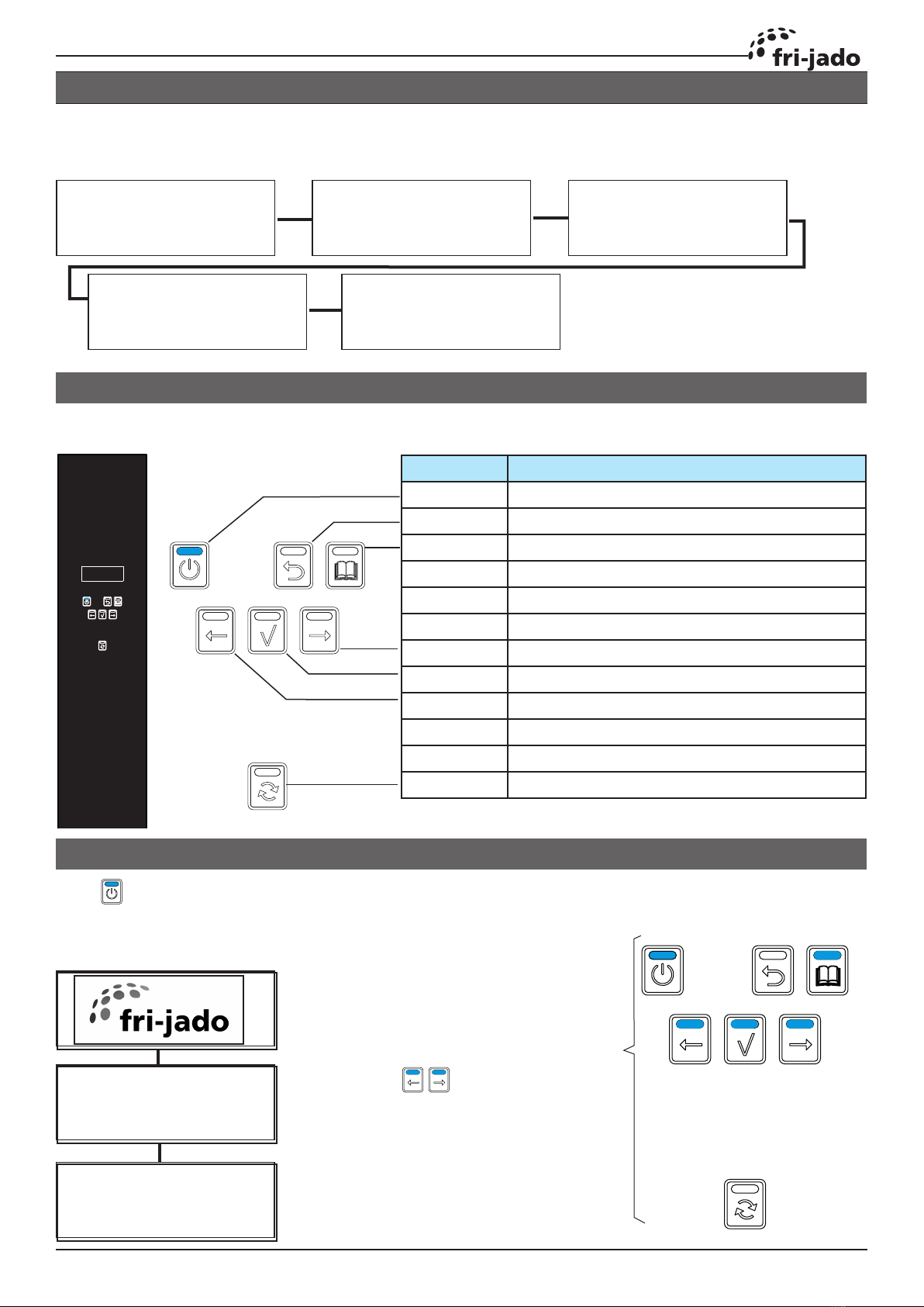
Overview of control panel .................................................................................................................... 7
Switching on .......................................................................................................................................... 7
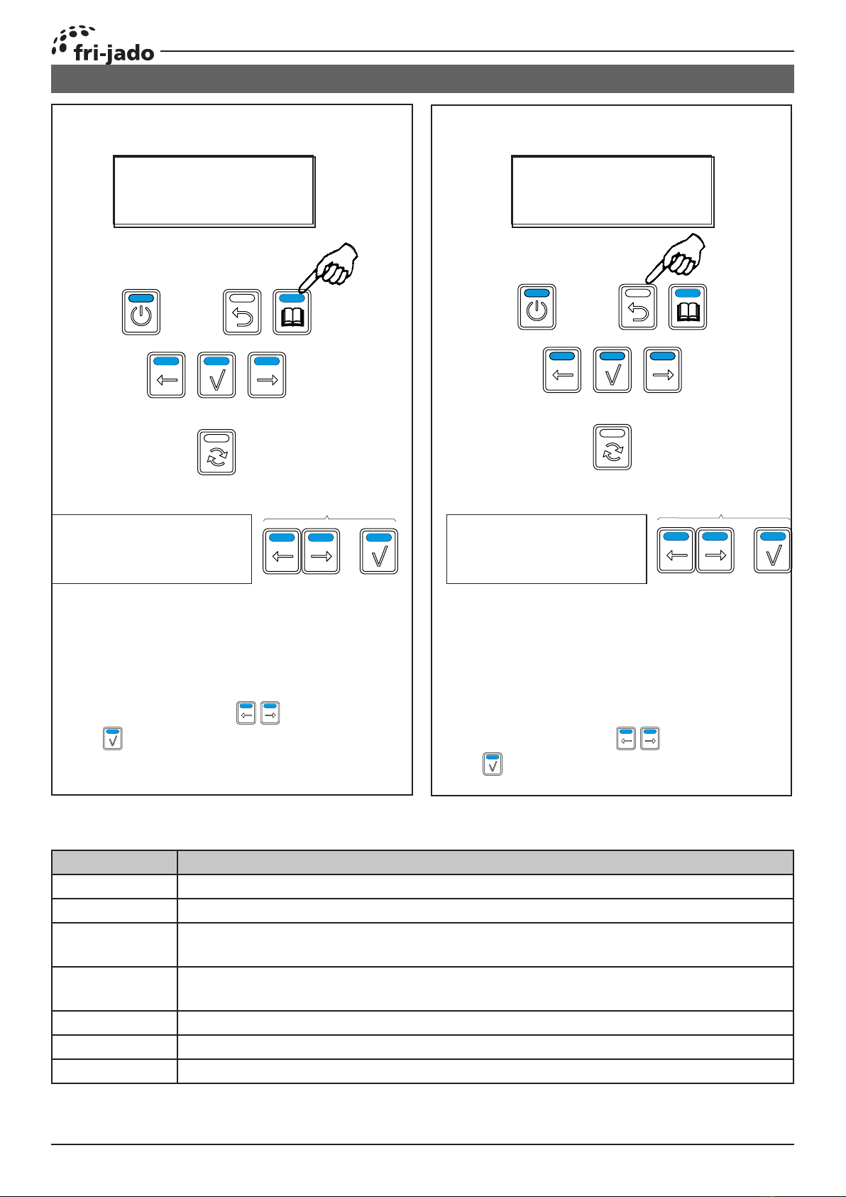
Entering the Manager or Service menu ............................................................................................... 8
The USB option read and store (cook books or parameters).......................................................... 10
The USB option transfer (error log and parameter settings)........................................................... 10
Files on the USB drive (strict rules) ..................................................................................................... 11
Updating software TDRp.................................................................................................................... 11
Manager and Service parameters ....................................................................................................... 13
Description of parameters................................................................................................................... 14
The automatic cook correction ........................................................................................................... 16
Default parameters EUR...................................................................................................................... 17
TDR i Programming instructions........................................................................................................... 19
MEnu settings TDRac ....................................................................................................................... 19
MEnu settings TDR-i ........................................................................................................................ 20
First Settings and Diagnostic Tools TDR-i ................................................................................... 21
I/O test TDR-i ....................................................................................................................................... 22
Updating software TDR-i.................................................................................................................... 23
Default parameters Version 6.01.27 TDR-i ........................................................................................ 24
Service procedures.................................................................................................................................. 26
Access to service parts TDR-p (2020)................................................................................................... 26
Access to service parts stacked units................................................................................................... 27
Operating panel (general) .................................................................................................................. 28
CPU board ............................................................................................................................................ 28
Broken buzzer...................................................................................................................................... 29
Keypad.................................................................................................................................................. 29
Door switch .......................................................................................................................................... 30
Rotor switch ......................................................................................................................................... 30
Replacing a lamp ................................................................................................................................. 31
lamp holder.......................................................................................................................................... 31
Blower motor....................................................................................................................................... 32
Heating element.................................................................................................................................. 33
Rotor drive motor................................................................................................................................ 34
High limit thermostat.......................................................................................................................... 36
PT 1000 sensor...................................................................................................................................... 36
Door inside........................................................................................................................................... 37
Door outside ........................................................................................................................................ 37
Electrical tests.......................................................................................................................................... 38
Measuring the heating elements....................................................................................................... 38
Measuring the Blowers....................................................................................................................... 38
Measuring the Rotor (drive) motor ................................................................................................... 40
Measuring the 500W lamp................................................................................................................. 40
Measuring the PT1000 sensor ............................................................................................................ 40
Trouble shooting ..................................................................................................................................... 41
Overview of error codes TDR-p........................................................................................................... 41
Error 55 explanation............................................................................................................................ 42
Trouble shooting by Symptom............................................................................................................ 43
Trouble shooting by part / function. .................................................................................................. 45

Page 5
TABLE OF CONTENTS
Service Manual Turbo Deli RotisserieII form 9120929 rev. 04/2021
Trouble shooting the TDW warmer.................................................................................................... 49
Exploded views and partslists ............................................................................................................... 50
TDRp, Electrical parts.......................................................................................................................... 50
TDRp, Parts list Electrical parts........................................................................................................... 51
TDR-p/I Connectors and wiring ........................................................................................................... 52
TDR-p/I Parts list Connectors and wiring ............................................................................................ 53
TDR-p/I, Electrical parts untill serial number 100097687.................................................................. 54
TDR-p/I, Parts list Electrical parts untill serial number 100097687................................................... 55
TDRm, Electrical parts......................................................................................................................... 56
TDRm, Parts list Electrical parts ......................................................................................................... 57
TDr Doors ............................................................................................................................................ 58
TDr Parts list Doors ............................................................................................................................. 59
TDR Illumination................................................................................................................................. 60
TDR Parts list Illumination.................................................................................................................. 61
TDR 5 Rotor......................................................................................................................................... 62
TDR 7/8 Rotor...................................................................................................................................... 62
TDR 5 Parts list Rotor.......................................................................................................................... 63
TDR 5 Heating..................................................................................................................................... 64
TDR 7/8 Heating.................................................................................................................................. 64
TDR 5/7/8 Parts list Heating................................................................................................................ 65
TDR 5 Sheet metal .............................................................................................................................. 66
TDR 5 Parts list Sheet metal ............................................................................................................... 67
TDR 7/8 Sheet metal ........................................................................................................................... 68
TDR 7/8 Parts list Sheet metal ............................................................................................................ 69
Fasteners............................................................................................................................................... 70
Electrical diagrams ................................................................................................................................. 72
Circuit diagram TDR 5P and 8p (from serial nr. 100097688) ............................................................. 72
Wiring diagram TDR 5P and 8p (from serial nr. 100097688)............................................................ 73
Overview of CPU board....................................................................................................................... 74
Overview of Power & I/O board (from serial nr. 100097688) ........................................................... 75
Circuit diagram TDR 5P and 8p (Untill serial nr. 100097687) ........................................................... 76
Wiring diagram TDR 5P and 8p (untill serial nr. 100097687) ........................................................... 77
Circuit diagram TDR 5m and 8m......................................................................................................... 78
Wiring diagram TDR 5m and 8m ........................................................................................................ 79
Circuit diagram TDW 5 ........................................................................................................................ 80
Circuit diagram TDW 8 ........................................................................................................................ 80
Wiring diagram TDW 5........................................................................................................................ 81
Wiring diagram TDW 8........................................................................................................................ 81
Electrical diagrams (before May 2014)................................................................................................. 82
Circuit diagram TDR 5P and 8p (untill serial number 100067527)................................................... 82
Wiring diagram TDR 5P and 8p (untill serial number 100067527) .................................................. 83
Circuit diagram TDR 5P and 8p (untill 01-07-2012) .......................................................................... 84
Wiring diagram TDR 5P and 8p (untill 01-07-2012).......................................................................... 85
Circuit diagram TDR 5m and 8m (untill 01-07-2012) ........................................................................ 86
Wiring diagram TDR 5P and 8p (untill 01-07-2012).......................................................................... 87

Page 6 Service Manual Turbo Deli RotisseriePKII form 9120929 rev. 04/2021
This manual covers the TDR electric oven models.
All of the information, illustrations and specifications contained in this manual are based on the
latest product information available at the time of printing.
GENERAL TECHNICAL DATA
TECHNICAL DATA
European Models TDR 5 TDR 8 TDR 5+5 TDR 8+8
Dimensions
- Width 835 mm 995 mm 835 mm 995 mm
- Depth 710 mm 830 mm 710 mm 830 mm
- Height 895 mm 1050 mm 1775 mm 2080 mm
Weight
- Gross 160 kg 210 kg 300 kg 425 kg
- Net 130 kg 185 kg 266 kg 375 kg
Maximum ambient temperature 35 °C 35 °C 35 °C 35 °C
Sound pressure < 70 dB(A) < 70 dB(A) < 70 dB(A) < 70 dB(A)
Electrical installation
- Voltage 3N~ 400/230
V
3N~
400/230 V
3N~ 400/230 V 3N~
400/230 V
- Frequency 50/60 Hz 50/60 Hz 50/60 Hz 50/60 Hz
- Required power 6.6 kW 10,5 kW 13.2 kW 21 kW
- Max. nom. current 10.0 A 15.5 A 20 A 31 A
Plug CEE-form
16 A
CEE-form
16 A
CEE-form 32 A CEE-form
32 A
Length of power cable approx. 2,20 m 2,20 m 2,20 m 2,20 m
American Models TDR 5 TDR 7 TDR 5+5 TDR 7+7
Dimensions
- Width 33 inch 39 ¼ inch 33 inch 39 ¼ inch
- Depth 28 inch 32 ¾ inch 28 inch 32 ¾ inch
- Height 35 ¼ inch 41 ¼ inch 70 inch 82 inch
Weight
- Gross 353 lbs 463 lbs 661 lbs 937 lbs
- Net 287 lbs 408 lbs 586 lbs 827 lbs
Maximum ambient temperature 95 °F 95 °F 95 °F 95 °F
Sound pressure < 70 dB(A) < 70 dB(A) < 70 dB(A) < 70 dB(A)
Electrical installation
- Voltage 3~ 208 V 3~ 208 V 3~ 208 V 3~ 208 V
- Frequency 50/60 Hz 50/60 Hz 50/60 Hz 50/60 Hz
- Required power 6.6 kW 10.5 kW 2x 6.6 kW 2x 10.5 kW
- Max. nom. current 18.9 A 30.8 A 2x 18.9 A 2x 30.8 A
Plug NEMA15-30P NEMA 15-
50P
2x NEMA 15-
30P
2x NEMA
15-50P
Length of power cable approx. 75 inch 75 inch 75 inch (2x) 75 inch (2x)
Tools
• Standard set of tools.
• Metric wrenches, sockets and hex socket key wren-
ches.
• Multi-meter and AC current clamp meter.
• Temperature tester.
• Insulation value tester (Megger).
• Field Service Grounding Kit.

Page 7Page 7
Service Manual Turbo Deli RotisserieII form 9120929 rev. 04/2021
CONNECTING MAINS POWER
PROGRAMMING INSTRUCTIONS TDR P
Push to switch on. (push 3 seconds to switch off)
The following messages appear.
Note the software version (firmware)
Key Function
ON / OFF Switching the unit on / off (3 sec)
UNDO Go back to previous menu
LIST Recipe / Programming modus
FORWARD One step ahead in choice / setting
OK Acknowledge a function or change
BACK One step back in choice / setting
ROTOR Switching the rotor ON
Functional keys are lit. In this case only the On / Off key. (mains is connected)
Messages on screen when connecting mains power.
Note the bootloader version.
SWITCHING ON
OVERVIEW OF CONTROL PANEL
Rotisserie in “ON” position.
The keys are only il-
luminated when more than
2 programs are stored.
Bootloader (Vx.xx.xx) Bootloader (Vx.xx.xx)
No USB stick found
Starting application
Bootloader (Vx.xx.xx)
Loading application
In progress ...%
Parameters init OK
Read language files
Bootloader (Vx.xx.xx)
Checking CRC
In progress ...%
Interface P Eco
TDR
Version x.x.x
Chicken
98 99 1 223 4 6 6 7

Page 8
PROGRAMMING INSTRUCTIONS
Service Manual Turbo Deli RotisseriePKII form 9120929 rev. 04/2021
4 8 7 8
default 1 1 1 1
ENTERING THE MANAGER OR SERVICE MENU
Entering the manager menu Entering the service menu
Choose figure
and confirm (4x)
Choose figure
and confirm (4x)
5 sec.
The following options appear on the
bottom line.
Usb - Programming- Parameters- Change
pin- Clock- Transfer- Version.
Select an option with and confirm
with
The following options appear on the
bottom line.
Usb - Function- Parameters- Clock- Counter-
Operation- User pin- Fault- Test Prog- Set
Demo On.
Select an option with and confirm
with
Option Description
USB Store cook-books to USB, or Read cook-books from USB
Programming Make, edit or delete cooking programs
Parameters Edit manager parameters. (service parameters include these as well)
See manager parameters below.
Change pin Pin 0000 gives free access. Default Pin code is 1111. Only active if in the
service menu, the <user Pin in use> parameter is set to <Y>
Clock Set time / date and format time / date (12 / 24 clock)
Transfer Stores error log and parameter settings on 2 separate files on USB
Version Shows the software version
Options in the manager menu
Chicken
98 99 1 223 4 6 6 7
Chicken
98 99 1 223 4 6 6 7
Pin 0 . . .
Enter your user code
Pin 0 . . .
Enter your service code

Page 9Page 9
PROGRAMMING INSTRUCTIONS
Service Manual Turbo Deli RotisserieII form 9120929 rev. 04/2021
Option Description
USB Store cook-books and / or parameters to USB.
Read cook-books and / or parameters from USB.
Function Function test of inputs and outputs, including the keypad
Parameters Edit manager parameters.
Clock Set time / date and format time / date (12 / 24 clock)
Counter In this menu you can view the total working hours of the fan, gearbox and
heaters. After replacing one of these parts you have to set the counter on
zero again.
Operation In this menu you can view the total hours of operation of the rotisserie. This
value is not resettable.
User pin In this menu you can view the current set pincode. This code can only be
viewed and not changed.
Fault In this menu you can view all occurred errors and, if applied, in what
cooking program.
Test prog In this menu you can start a test program. This fixed program has one
cooking step of 250°C for 20 minutes and a holding program of 85°C and 10
minutes.
Set demo on In this menu you can set the machine into a demonstration mode. In de-
monstration mode the machine will not turn the heating elements on and
will simulate the machine heating.
Options in the service menu

Page 10
PROGRAMMING INSTRUCTIONS
Service Manual Turbo Deli RotisseriePKII form 9120929 rev. 04/2021
Manager menu
USB Edit
Servicemenu
USB Fu..
THE USB OPTION READ AND STORE (COOK BOOKS OR PARAMETERS)
USB read and store
Read Sto.
USB read and store
Read Store
Read from stick
Recipes Par.
Store on stick
Recipes Par.
A-------------
Save File nameRead stick
Choice of parameters only in ser-
vice menu
Enter the manager or service menu as described before.
Also see chapter “Files on USB drive”
THE USB OPTION TRANSFER (ERROR LOG AND PARAMETER SETTINGS)
Choose character with and
for next one.
Finally push on an empty field
and again to save.
When reading Recipes (cook-books) or Parameters from the USB drive,
you have to choose which one, if there is more then one file.
Manager menu
Clk Transfer Vers.
Enter the manager menu as described before.
Also see chapter “Files on USB drive”
Insert stick and press
enter
2 files are being stored in the folder “DUMP”.
These are “log.csv” and “params.csv”
Cook-books are stored or red from the folder “PROGRAMS” .
Parameters are stored or red from the folder “PARAMETERS”.
The files are .csv files
Insert the USB drive and press
Read Store

Page 11
PAR1.CSV
PAR2.CSV
AUTOPAR.CSVAUTOPAR.CSV
PROG1.CSV
PROG2.CSV
AUTOPROG.CSVAUTOPROG.CSV
Page 11
PROGRAMMING INSTRUCTIONS
Service Manual Turbo Deli RotisserieII form 9120929 rev. 04/2021
FILES ON THE USB DRIVE (STRICT RULES)
These files can be found on the USB drive
regarding the TDRp.
The highligted folders and files are fixed and
made by the TDRp controller.
The other files can be named by yourself, but
there are strict rules.
Note that all files are .csv files and can be red
or modified with applications like excell.
The parameter files in “DUMP”and ”PA-
RAMS” contain the complete parameter list,
including the service parameters.
The files in “PROGRAMS” contain a list of
recipes.
Strict rules for folders and files on the USB drive.
• Own made programs have to be put in the folder “PROGRAMS”.
• Customized parameter lists have to be put in the folder “PARAMS”.
• The name of a file may not exist of more than 8 characters and can’t have a space bet-
ween the characters.
• It is not allowed to have an open line in the “excell” recipe list.
• All file names must have the extension “.csv”.
When the message “files not found” is indicated on the display, one of the above might not
be in order.
Also malfunction of the USB drive can occur.
A software update might help too.
UPDATING SOFTWARE TDRP
Updating the software can be done:
• When certain features come available
• When a bug is fixed.
• When the controller is acting strange or crashed
The zip file with the latest software can be found on the Fri-
Jado website.
At the moment of writing, this is version V1_05_07.
It is not necessary to place this zip file on the USB drive.
The folder 42-P+CPU however must be copied or moved di-
rectly on the USB stick. Not in a folder deeper!
See update procedure on next page
Automatic uploadingAutomatic uploading of parameters and programs.
Be sure that the parameters and programs are copied in files with the names “autoparautopar” or
“autoprogautoprog” on a USB drive.
Put the USB drive in the socket and switch ON the rotiserie. Wait for the message to take
out the USB drive.

42-P+CPU
Page 12
PROGRAMMING INSTRUCTIONS
Service Manual Turbo Deli RotisseriePKII form 9120929 rev. 04/2021
Bootloader version V1.01.02
-USB stick found
starting upgrade
-Checking CRC
In progress
-Copying file
-Loading application
-Checking CRC
-Please remove USB stick
to start application
2. Connect the USB drive.
1. Disconnect the mains supply
3. Connect the mains supply
5. Disconnect the USB drive.
4. The following messages appear
The software comes in a .zip le. The name cor-
responds with the version of the software. For
example: V1_05_07.zip.
1. Extract the zip le
2. Copy or move the folder “42-P+CPU” to the
USB drive.
Preparing the software (rmware)
Updating the software (rmware)

Page 13
4 8 7 8
Page 13
PROGRAMMING INSTRUCTIONS
Service Manual Turbo Deli RotisserieII form 9120929 rev. 04/2021
MANAGER AND SERVICE PARAMETERS
Entering the manager parameters Entering the service parameters
Use and <Next Par.> to scroll through the parameter list.
Push for the < Change> option and confirm .
Use and to change and jump back to <Next Par>
Use to scroll to <Save>, confirm with and confirm again with
Use to step back (undo) if applicable.
Note that the manager menu only shows the green fields from the list below.
Manager menu
Edit Parameters Pin
Pin 0 . . .
Enter your user code
Servicemenu
Fu.. Parameters Ci..
Pin 0 . . .
Enter your service code
Preheat allowed: NO
Cha. Next Par. Prev
Choose figure
and confirm (4x)
Choose figure
and confirm (4x)
5 sec.
Chicken
98 99 1 223 4 6 6 7
Chicken
98 99 1 223 4 6 6 7
default 1 1 1 1

Page 14
PROGRAMMING INSTRUCTIONS
Service Manual Turbo Deli RotisseriePKII form 9120929 rev. 04/2021
1 Only visible when “Cook Corr. option” in Service Menu is set on “yes”
2 Only visible when “Ecocook option” in Service Menu is set on “yes”
Parameter Description
Preheat allowed Enables or disables a preheat step prior to the cooking program (steps)
Yes > Preheat is allowed. In the cooking program you can still choose
whether or not to preheat.
No > Preheat is disabled.
Preheat temp This is the default preheat temperature setting. Can be changed in the
cooking program.
Holding allowed Enables or disables a warm hold step at the end of the cooking program.
If “no” is selected holding is not possible, even if there is a program with
a holding tep.
Holding temp This is the default holding temperature setting. Can be changed in the
cooking program.
*Cook correction*Cook correction
Cook corr. option
Enables or disables the cook correction function. See description below.
Cook cor. fact.
* Eco function* Eco function
Ecocook option
Enables or disables the Eco mode.
The heating is being switch of a few minutes before and the accumu-
lated heat of the cooking cavity will be used to finish the product. The
cooking time wil be a few minutes longer.
Ecocook var. This parameter alows to set the variable of the ecocook. Var. adjustable
from 1 to 9. This is the percentage of the total cooking time.
Language Choose of available language.
Big digits Choice for big digits on the display during preheat, cooking and hold
cycle.
Sound preheat
T1
Choice of sound at the end of the preheat step. You can choose 3 diffe-
rent sounds (T1-T2-T3) and the level of the sound (up to 4 white blocks)
or no sound (no white block).
Sound step T2 Choice of sound at the end of the first grilling step. You can choose 3
different sounds (T1-T2-T3) and the level of the sound (up to 4 white
blocks) or no sound (no white block).
Sound done T2 Choice of sound at the end of the grilling step(s). You can choose 3 diffe-
rent sounds (T1-T2-T3) and the level of the sound (up to 4 white blocks)
or no sound (no white block).
Temp. unit: Choice of Celcius (°C) or Fahrenheit (°F).
Boost allowed Possibility to add extra cooking time in minutes at the end of the
cooking cycle.
User PIN in use N No pin code will be asked for the manager menu
Y Unless changed, the default pincode 1111 will be asked. 0000 will
still be free access
DESCRIPTION OF PARAMETERS
In the manager menu, only the green parameters are visible

Page 15Page 15
PROGRAMMING INSTRUCTIONS
Service Manual Turbo Deli RotisserieII form 9120929 rev. 04/2021
Parameter Description
Lights out Choice of lighting during opening of the door in standby position.
Y The lights will go on for 20 seconds.
key beep choice for beep or no beep, with key operation.
Temp. offset Temperature offset of PT1000 sensor.
Example: at a set point of 180°C (355°F) and an offset of -20°C (-35°F) ,
the oven cavity will be controlled on 200°C (390°F)
Key sens Adjustment of the sensitivity of the keys. Sensitivity is highest on value 1
and lowest on 9.
Temp. grad. This parameter allows the setting of the minimal temperature rise, in °C
/ 2minutes, of the PT sensor during the preheat, cooking or hold step.
This parameter is used for the error 55 test.In this test the measuring
only starts 5 minutes after beginning of a heating step. Duration of the
test is 5 periods of 2 minutes. Measuring stops at 150°C/302°F or when
temp. in the cabinet is < 30°C than the set temperature. When the
temperature rise is lower than 0.5°C per 2 minutes during 5 consecutive
periods, an “error 55” will be indicated and the machine switches off.
Second display Setting of the display on customer side.
0 = Second display has only the rotor function.
1 = Second display has only limited functions like viewing during
cooking proces.
2 = As 1 + possibility of selection of programs and starting.
3 = Not in use.
Thermistor Enables or disables the detection of the thermistor in the blower . See
error 66.
Hood check Enables detection of feedback signals from the hood, if applicable. Not
in EUR versions.
See error 91 and 92

Page 16
PROGRAMMING INSTRUCTIONS
Service Manual Turbo Deli RotisseriePKII form 9120929 rev. 04/2021
The program calculates the surface from the
diagram below the curved line. (tempera-
ture * time). The result is the so called heat
number. This heat number is stored into
the cooking program.
All further cooking programs will try to get
the same heat number.
The second diagram shows an example with
full load. It takes more time for the unit to
reach the programmed cooking tempera-
ture. See dashed line. The surface above
the dashed line represents the missing part
of the heat number. The cook correction
will put this missing part behind the nor-
mal cooking time. Therefore extra time is
added in order to reach the desired heat
number.
It is also possible that time is deducted in case
a smaller load has been put into the oven.
Time will be added in case of:
A bigger load.
A colder load. (straight from the freezer)
A lower mains voltage.
Somebody opened the door.
Time will be deducted in case of:
A smaller load.
A warmer load. (defrosted)
Higher mains voltage.
Note that:
In case the time or temperature will be
changed in the cooking program, the heat
number will be adapted with this amount.
THE AUTOMATIC COOK CORRECTION
°C
°C
Extra time
Cooking time
Temparature curve
with half load
The automatic cook correction facility will automaticly add or deduct time to the pro-
grammed cooking time in order to have constant cooking quality.
After programming a new program, the first cooking process will be the “learning” process.
It is recommended to do the first cook with a half load.
The heat number is stored in the cooking
program. In case such a program is cop-
ied with FIPS (see additional software),
the heat number goes with it.
It is possible that in case the program has
changed a lot, the cook correction is not
able to perform well anymore. In that
case the program has to be deleted and
reprogrammed with the good param-
eters.
It is possible to disable this auto cook cor-
rection feature in the service parameters.
See “parameter listings” -> “auto correct.
Full load
Half load

Page 17Page 17
PROGRAMMING INSTRUCTIONS
Service Manual Turbo Deli RotisserieII form 9120929 rev. 04/2021
Level 1 Level 2 Default Possibilities
Information 1.05.2007 software version
Manager 1111
Preheat allowed yes yes - no
Preheat temp 210 50 - 250
Holding allowed no yes - no
Holding temp 85 50 - 250
Cook Correction 1yes yes - no
Eco function 2yes yes - no
Language English "English - Nederlands - Deutsch - Francais -Espanol - Russian"
Big Digits yes yes - no
Sound preheat T1, T1 - T2 - T3
Sound step T2, T1 - T2 - T3
Sound done T3, T1 - T2 - T3
Service 4878
Preheat allowed yes yes - no
Preheat temp 210 50 - 250
Holding allowed no yes - no
Holding temp 85 50 - 250
Cook corr. Option yes yes - no
Cook corr. factor 3 1 - 6
Ecocook option yes yes - no
Ecocook var 6 1 - 9
Language English "English - Nederlands - Deutsch - Francais -
Espanol - Russian"
Big Digits yes yes - no
Sound preheat T1, T1 - T2 - T3
Sound step T2, T1 - T2 - T3
Sound done T3, T1 - T2 - T3
Temp unit °C °C - °F
Boost allowed no yes - no
User pin in use no yes - no
Lights out yes yes - no
Key beep no yes - no
Temp offset 0 -50 - +50°C or -100-+100°F
Key sense 7 1 - 11
Temp grad 3 "0 - 19
0 = disable error 55"
Second Display 0 0-1-2-3
Thermistor 3no yes - no
Hood Check no yes - no
DEFAULT PARAMETERS EUR
1 Only visible when “Cook Corr. option” in Service Menu is set on “yes”
2 Only visible when “Ecocook option” in Service Menu is set on “yes”
3 May be put on yes in case serial number higher than 100067526

Page 18
PROGRAMMING INSTRUCTIONS
Service Manual Turbo Deli RotisseriePKII form 9120929 rev. 04/2021
EMPTY PAGEEMPTY PAGE

Page 19
Service Manual Turbo Deli RotisserieII form 9120929 rev. 04/2021
MENU SETTINGS TDRAC
To enter the set up of the TDR AC
press the on/o key for 3 seconds.
The main screen will show 3 options:
• operate
• program
• settings
Select the program by pushing the
corresponding key.
Within the program menu the user can
edit or add additional cooking pro-
grams.
The cooking programs can be “pin
code” protected in the manager menu.
The operator menu will allow the user
to run cooking and cleaning programs
Selection buttons
Display
Rotation pad
Operate
Program
on/ o key
TDR I PROGRAMMING INSTRUCTIONS

TDR i Programming instructions
Page 20 Service Manual Turbo Deli RotisseriePKII form 9120929 rev. 04/2021
MENU SETTINGS TDR-I
Information
The Information screen will display the following information
about the rotisserie:
• Device type (TDRi)
• Firmware version of the CPU board (version: 6.01.27
• Last error
• Firmware version of the I/O board (MFMB:v1.00)
Manager
The manager settings are used to change local settings like
temperature, date/time or to load recipes. A complete overview
can be found in the TDR ac service manual.
No pin code is required if it is set to the default value “0000”
Settings
Service
A complete overview of service settings is available. Use pin code
4878 to enter the menu.
This manual suits for next models
3
Table of contents
Other Fri-Jado Grill manuals
Popular Grill manuals by other brands

Roundup Food Equipment Division
Roundup Food Equipment Division HOT DOG CORRAL HDC owner's manual

Heritage
Heritage 200 user guide

Barbecook
Barbecook Basic User manual and assembly instructions

Weber
Weber Genesis 1300 owner's manual

Julien
Julien HOME REFINEMENTS KAMADO Installation and maintenance guide

Weber
Weber Summit E 470 Assembly instructions