Frico AR4200 Series User manual

Original instructions
AR4200
.... 20
SE
.... 59
PL
.... 34
FR
.... 29
NO
.... 64
RU
.... 25
GB .... 39
DE
.... 49
NL .... 54
IT
.... 44
ES

AR4200
2
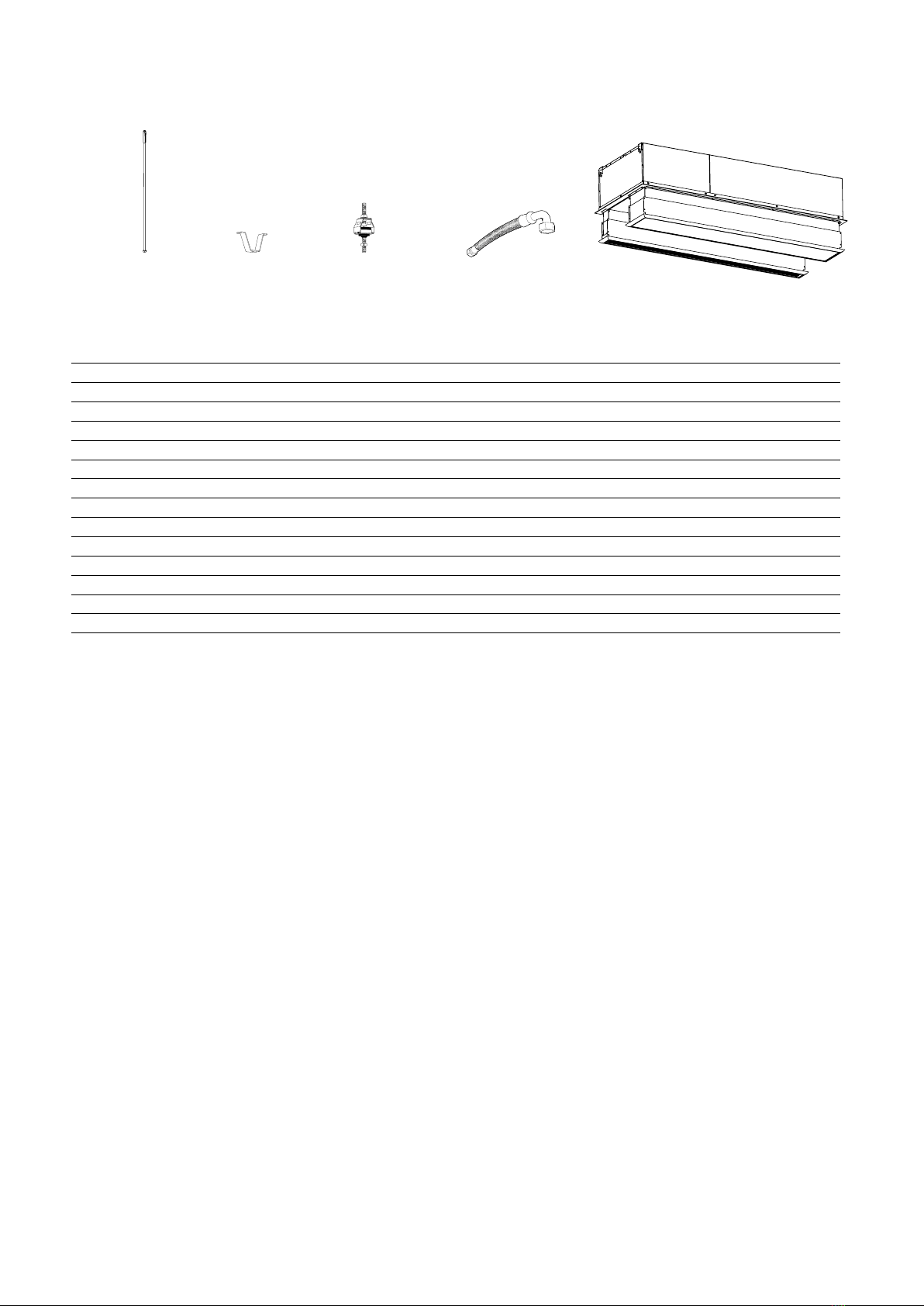
Introduktionssidorna består huvudsakligen av bilder. För översättning av de
engelska texter som används, se respektive språksidor.
SE
The introduction pages consist mainly of pictures. For translation of the
English texts used, see the respective language pages.
GB
Introduksjonssidene består hovedsakelig av bilder. For oversettelse av de
engelske tekstene, se de respektive språksidene
NO
Les pages de présentation contiennent principalement des images. Consulter
la page correspondant à la langue souhaitée.
FR
Die Einleitungsseiten bestehen hauptsächlich aus Bildern. Für die Übersetzung
der verwendetenTexte in englischer Sprache, siehe die entsprechenden
Sprachseiten.
DE
Las páginas introductorias contienen básicamente imágenes. Consulte la
traducción de los textos en inglés que las acompañan en las páginas del
idioma correspondiente.
ES
De inleidende pagina's bevatten hoofdzakelijk afbeeldingen. Voor een vertaling
van de gebruikte Engelse teksten, zie de pagina's van de resp. taal.
NL
Le pagine introduttive contengono prevalentemente immagini. Per le
traduzioni dei testi scritti in inglese, vedere le pagine nelle diverse lingue.
IT
Początkowe strony zawierają głównie rysunki. Tłumaczenie wykorzystanych
tekstów angielskich znajduje się na odpowiednich stronach językowych.
PL
RU Страницы в начале Инструкции состоят в основном из рисунков, схем и
таблиц. Перевод встречающегося там текста приведен в разделе RU.

B
A
1 m: 4 x M8
1,5 m: 4 x M8
2 m: 6 x M8
2,5 m: 6-8 x M8
803
851
851
296
53 90
218
ø29
ø29
ø20
A
[mm]
B
[mm]
AR4210 1067 1020
AR4215 1577 1520
AR4220 2067 2020
AR4225 2579 2520
AR4200
3

AR4200
4
Mounting on threaded bars outside the unit
AR4215
AR4210
Top view
884
851
71
56
218
1400
851
851
851
945
1198 1198
945
ø29
ø20
ø29
AR4220
AR4225

AR4200
5
Fig. 1b. Mounting on threaded bars outside the unit.
Mounting on threaded bars outside the unit
Fig. 1a: Mounting brackets on delivery.
AR4220
AR4225

AR4200
6
Mounting on threaded bars inside the unit
AR4215
AR4210
Top view
AR4220
AR4225
363 340
430
430 56
56
430
56
430
56
291
291 994
411
368
754
666 666
484 218
71
56
291
292 828 339 828
742742
397 723 340 723
ø29
ø20
ø29

AR4200
7
1 m: 4 x M8
1,5 m: 4 x M8
2 m: 6 x M8
2,5 m: 6-8 x M8
Fig. 2. Mounting on threaded bars inside the unit.
Mounting on threaded bars inside the unit

Fig. 3: Snap fixings
90°
AR
Service hatch
Fig. 4: SIRe inside the unit.
Fig. 5: Hoses are mounted via cable glands at knockouts to protect the hose and prevent air leakage.
AR4200
8
1
2

Accessories
AR4200
9
PA34TR15 AR4210/4215 4 pcs L: 1 m
PA34TR20 AR4220 6 pcs L: 1 m
PA34TR30 AR4225 8 pcs L: 1 m
PA34CB15 AR4210/4215 4 pcs
PA34CB20 AR4220 6 pcs
PA34CB30 AR4225 8 pcs
PA34VD15 AR4210/4215 4 pcs
PA34VD20 AR4220 6 pcs
PA34VD30 AR4225 8 pcs
FHDN2010 AR4200W 2 pcs L: 1 m
AR42XTT10 AR4210 H: 130-210 mm
AR42XTT15 AR4215 H: 130-210 mm
AR42XTT20 AR4220 H: 130-210 mm
AR42XTT25 AR4225 H: 130-210 mm
PA34CBPA34TR PA34VD FHDN20 AR42XTT
See separate manual.

SIReB
SIReAC
SIReAA
SIReRTX 70x33x23 mm
SIReUR 114x70x50 mm
SIReWTA
SIReCJ4
SIReCJ6
SIReCC603 3 m
SIReCC605 5 m
SIReCC610 10 m
SIReCC615 15 m
SIReCC640 40 m
SIReCC403 3 m
SIReCC405 5 m
SIReCC410 10 m
SIReCC415 15 m
SIRe
C
SIReB
SIReAC/SIReAA
SIReRTX
SIReUR
SIReWTA
SIReCC
SIReCJ4/SIReCJ6
VKF15LF
DN15
VKF15NF
DN15
VKF20
DN20
VKF25
DN25
VKF32
DN32
SD230
BPV10
SDM24
ST23024
VOT15 DN15
VOT20 DN20
VOT25 DN25
VKF
SDM24 ST23024
SD230 BPV10
VKF
VLSP VLP
VOT
AR4200
10

AR4200 A
AR4200 W
AR4210 A/W
White
White
°C°C°C
Transformer
230V
200V
170V
145V
120V
100V
N
Yellow
Orange
Red
Brown
Black
Green
Blue
°C
AR4225/4220/4215 A/W
H1 H2N
Id RoomC2 C1 Actuator 230V Supply 230V
PE L
N
Heating
L
N
~
L
N F2 F3F1 F4 F5
Trafo
N
L
Motor
SIRe B1N
Trafo
Motor
protection
Internal
sensor
Blue
230V
200V
175V
145V
120V
100V
N
Transformer
230V~
AR4200
11

AR4210/4215 E
AR4210E 4210E/4215E
400V3~
Black
Grey
Blue
White
White
°C°C°C
Transformer
230V
C2
C1
200V
170V
145V
120V
100V
N
Yellow
Orange
Red
Brown
Black
Green
Blue
N
°C
AR4215E
H1 H2N
Id RoomC2 C1 Actuator 230V Supply 230V
PE L
N
Heating
L
N
~
L
N F2 F3F1 F4 F5
Trafo
N
L
Motor
SIRe B1N
Trafo
Motor
protection
Internal
sensor
Black
Blue
230V
200V
175V
145V
120V
100V
N
Transformer
230V~
L1L2 L3
AR4200
12

AR4220/4225 E
400V3~
Black
Grey
Blue
White
White
°C°C°C
Transformer
230V
C2
C1
C4
C3
200V
170V
145V
120V
100V
N
Yellow
Orange
Red
Brown
Black
Green
Blue
N
N
N
°C°C
AR4220/4225E
H1 H2N
Id RoomC2 C1 Actuator 230V Supply 230V
PE L
N
Heating
L
N
~
L
N F2 F3F1 F4 F5
Trafo
N
L
Motor
SIRe B1N
Trafo
Motor
protection
Internal
sensor
Black
Blue
230V
200V
175V
145V
120V
100V
N
Transformer
230V~
!
2× 400V3~
L1L2 L3
L1L2 L3 L1L2L3
AR4200
13

400V3~
Black
Grey
Blue
White
White
°C°C°C
Transformer
230V
C2
C1
C4
C3
200V
170V
145V
120V
100V
N
Yellow
Orange
Red
Brown
Black
Green
Blue
N
NN
°C°C
AR4220/4225E
2x 400V3~ supply
H1 H2N
Id RoomC2 C1 Actuator 230V Supply 230V
PE L
N
Heating
L
N
~
L
N F2 F3F1 F4 F5
Trafo
N
L
Motor
SIRe B1N
Trafo
Motor
protection
Internal
sensor
Black
Blue
230V
200V
175V
145V
120V
100V
N
Transformer
230V~ 400V3~
2× 400V3~
!
N
NN
NN
1× 400V3~
2× 400V3~
NN
2× 400V3~
00V
AR4220/4225 E
2x 400V3~
AR4200
14

SIReB Basic
AR4200 A / AR4200 E
Wiring diagrams for SIReAC Competent and SIReAA Advanced, see manual for SIRe.
C2
X5
C1
X4
ROOM
X3
Pot.
Unit ID ACTUATORSUPPLY
N L NL
PE
L
~
230V~
C2
X5
C1
X4
ROOM
X3
Pot.
Unit ID ACTUATORSUPPLY
N L NL
PE
L
~
230V~
C2
X5
C1
X4
ROOM
X3
Pot.
Unit ID ACTUATORSUPPLY
N L NL
PE
L
~
230V~
SIReCC6XX (max 50 m)
SIReCC6XX
(max 50 m)
SIReCC6XX
(max 50 m)
SIReUB1
SIReRTX
(optional)
L=2m
SIReB1/B2/B1EC
SIReB1/B2/B1EC
SIReB1/B2/B1EC
AR4200
15

Wiring diagrams for SIReAC Competent and SIReAA Advanced, see manuals for SIRe.
SIReB Basic
AR4200 W
C2
X5
C1
X4
ROOM
X3
Pot.
Unit ID ACTUATORSUPPLY
N L NL
PE
L
~
230V~
C2
X5
C1
X4
ROOM
X3
Pot.
Unit ID ACTUATORSUPPLY
N L NL
PE
L
~
230V~
C2
X5
C1
X4
ROOM
X3
Pot.
Unit ID ACTUATORSUPPLY
N L NL
PE
L
~
230V~
SIReCC6XX (max 50 m)
SIReB1/B2/B1EC
SIReB1/B2/B1EC
SIReB1/B2/B1EC
SIReCC6XX
(max 50 m)
SIReCC6XX
(max 50 m)
SIReUB1
SIReRTX
(optional)
SD230
SD230
SD230
L=1,5m
L=2m
AR4200
16

*1) Recommended outlet air temperature for good comfort and optimized output.
*2) Nominal output at given supply and return water temperature.
AR4200
17
Supply water temperature:80 °C
Room temperature: +18 °C
Outlet air temperature: +35 °C*1
Water temperature: 80/60 °C
Room temperature: +18 °C
Type Fan
position
Airflow
[m3/h]
Output
[kW]
Return water
temp.
[°C]
Water
flow
[l/s]
Pressure
drop
[kPa]
Output *2
[kW]
Outlet
air temp.
[°C]
Water
flow
[l/s]
Pressure
drop
[kPa]
AR4210W max 2700 15,2 31 0,07 2,9 29,1 49,6 0,36 43,9
min 110 0 6,6 27 0,03 0,6 15,6 59,5 0,19 14,1
AR4215W max 3800 21,7 30 0,11 2,2 43,3 51,4 0,53 38,4
min 1600 9,5 27 0,04 0,5 23,3 60,7 0,29 12,5
AR4220W max 5500 32,1 31 0,16 2,1 61,6 50,8 0,75 33,4
min 2300 13,4 27 0,06 0,4 33,2 60,3 0,41 10,9
AR4225W max 6500 38,7 29 0,18 3,3 75,8 52,2 0,93 57,8
min 2700 15,8 24 0,07 0,6 40,2 61,7 0,49 18,3
Output charts water AR4200W - Standard coil
Supply water temperature:70 °C
Room temperature: +18 °C
Outlet air temperature: +35 °C*1
Water temperature: 70/50 °C
Room temperature: +18 °C
Type Fan
position
Airflow
[m3/h]
Output
[kW]
Return water
temp.
[°C]
Water
flow
[l/s]
Pressure
drop
[kPa]
Output *2
[kW]
Outlet
air temp.
[°C]
Water
flow
[l/s]
Pressure
drop
[kPa]
AR4210W max 2700 16,1 35 0,11 5,7 23,1 43 0,28 29,5
min 110 0 6,3 28 0,04 0,8 12,4 51 0,15 9,7
AR4215W max 3800 22,1 32 0,14 3,8 34,3 44,4 0,42 25,7
min 1600 9,4 28 0,05 0,7 18,6 52,1 0,23 8,5
AR4220W max 5500 32,2 33 0,21 3,6 48,8 44 0,59 22,3
min 2300 13,2 28 0,08 0,6 26,4 51,7 0,32 7, 4
AR4225W max 6500 36,8 30 0,22 4,8 60,3 45,2 0,73 39
min 2700 15,4 25 0,08 0,9 32,2 53 0,39 12,6
Supply water temperature: 60 °C
Room temperature: +18 °C
Outlet air temperature: +35 °C*1
Water temperature: 60/40 °C
Room temperature: +18 °C
Type Fan
position
Airflow
[m3/h]
Output
[kW]
Return water
temp.
[°C]
Water
flow
[l/s]
Pressure
drop
[kPa]
Output *2
[kW]
Outlet
air temp.
[°C]
Water
flow
[l/s]
Pressure
drop
[kPa]
AR4210W max 2700 15,8 37 0,17 12,3 16,9 36,4 0,21 1 7, 4
min 110 0 6,4 30 0,05 1,5 9,2 42,4 0,11 5,9
AR4215W max 3800 21,6 35 0,21 7, 6 25,2 37,4 0,31 15
min 1600 9,2 29 0,07 1,2 13,8 43,2 0,17 5,1
AR4220W max 5500 32,0 36 0,32 7, 8 35,7 37 0,43 13,1
min 2300 13,5 30 0,11 1,1 19,6 42,9 0,24 4,5
AR4225W max 6500 38,8 35 0,37 12,0 44,6 38,1 0,54 23,2
min 2700 15,3 27 0,11 1,5 24 44,1 0,29 7, 7
Supply water temperature: 55 °C
Room temperature: +18 °C
Outlet air temperature: +35 °C*1
Water temperature: 55/35 °C
Room temperature: +18 °C
Type Fan
position
Airflow
[m3/h]
Output
[kW]
Return water
temp.
[°C]
Water
flow
[l/s]
Pressure
drop
[kPa]
Output *2
[kW]
Outlet
air temp.
[°C]
Water
flow
[l/s]
Pressure
drop
[kPa]
AR4210W max 2700 15,6 39 0,24 23,3 13,8 32,9 0,17 12,2
min 110 0 6,2 30 0,06 2,1 7, 5 38 0,09 4,2
AR4215W max 3800 21,8 37 0,29 14,2 20,5 33,8 0,25 10,5
min 1600 9,3 30 0,09 1,8 11,3 38,6 0,14 3,6
AR4220W max 5500 31,0 37 0,42 12,4 29,1 33,5 0,35 9,2
min 2300 13,2 30 0,13 1,6 16 38,4 0,19 3,2
AR4225W max 6500 38,7 37 0,52 22,1 36,6 34,5 0,44 16,5
min 2700 16,1 29 0,15 2,5 19,8 39,5 0,24 5,6

AR4200
18
Output charts water AR4200WLL - Special coil
*1) Recommended outlet air temperature for good comfort and optimized output.
*2) Nominal output at given supply and return water temperature.
Supply water temperature: 55 °C
Room temperature: +18 °C
Outlet air temperature: +32 °C*1
Water temperature: 55/35 °C
Room temperature: +18 °C
Type Fan
position
Airflow
[m3/h]
Output
[kW]
Return water
temp.
[°C]
Water
flow
[l/s]
Pressure
drop
[kPa]
Output *2
[kW]
Outlet
air temp.
[°C]
Water
flow
[l/s]
Pressure
drop
[kPa]
AR4210WLL max 2500 12,0 29 0,11 2,0 15,7 36,5 0,19 4,9
min 110 0 5,3 28 0,05 0,4 8,6 40,8 0,10 1,7
AR4215WLL max 3600 1 7, 2 27 0,15 2,0 24,3 37,8 0,29 6,4
min 1600 7, 6 26 0,06 0,5 13,1 42,1 0,16 2,2
AR4220WLL max 5200 25,1 29 0,23 1,6 33,3 36,8 0,40 4,2
min 2300 9,2 29 0,08 0,3 18 40,9 0,22 1,4
AR4225WLL max 6200 30,6 28 0,27 1,8 41,3 37,5 0,50 5,3
min 2700 13,9 28 0,13 0,5 21,9 41,8 0,27 1,7
Supply water temperature:50 °C
Room temperature: +18 °C
Outlet air temperature: +32 °C*1
Water temperature: 50/30 °C
Room temperature: +18 °C
Type Fan
position
Airflow
[m3/h]
Output
[kW]
Return water
temp.
[°C]
Water
flow
[l/s]
Pressure
drop
[kPa]
Output *2
[kW]
Outlet
air temp.
[°C]
Water
flow
[l/s]
Pressure
drop
[kPa]
AR4210WLL max 2500 12,0 30 0,15 3,2 11,9 31,9 0,14 3,1
min 110 0 5,1 27 0,05 0,6 6,4 35,1 0,08 1,1
AR4215WLL max 3600 1 7, 0 28 0,19 3,1 18,6 33,1 0,22 4,1
min 1600 7, 7 26 0,08 0,7 10 36,4 0,12 1,4
AR4220WLL max 5200 25,3 30 0,31 2,7 24,9 32,1 0,30 2,6
min 2300 11,3 28 0,13 0,6 13,2 34,9 0,16 0,8
AR4225WLL max 6200 30,1 29 0,35 2,9 31,3 32,8 0,38 3,3
min 2700 12,8 27 0,14 0,6 16,4 35,8 0,20 1
Supply water temperature: 45 °C
Room temperature: +18 °C
Outlet air temperature: +32 °C*1
Water temperature: 45/35 °C
Room temperature: +18 °C
Type Fan
position
Airflow
[m3/h]
Output
[kW]
Return water
temp.
[°C]
Water
flow
[l/s]
Pressure
drop
[kPa]
Output *2
[kW]
Outlet
air temp.
[°C]
Water
flow
[l/s]
Pressure
drop
[kPa]
AR4210WLL max 2500 12,8 32 0,24 7, 6 14,4 33,7 0,35 14,7
min 110 0 5,2 28 0,07 1,0 7, 3 37,5 0,18 4,5
AR4215WLL max 3600 1 7, 4 30 0,29 6,4 20,8 34,9 0,50 17
min 1600 7, 8 27 0,11 1,1 11,1 38,3 0,27 5,6
AR4220WLL max 5200 25,7 32 0,48 5,8 29 34,3 0,70 11,5
min 2300 11,0 28 0,16 0,9 15,5 37,7 0,37 3,8
AR4225WLL max 6200 29,6 30 0,49 5,2 35,6 34,8 0,86 14,4
min 2700 13,3 28 0,19 1,0 18,7 38,3 0,45 4,5
Supply water temperature: 40 °C
Room temperature: +18 °C
Outlet air temperature: +32 °C*1
Water temperature: 40/30 °C
Room temperature: +18 °C
Type Fan
position
Airflow
[m3/h]
Output
[kW]
Return water
temp.
[°C]
Water
flow
[l/s]
Pressure
drop
[kPa]
Output *2
[kW]
Outlet
air temp.
[°C]
Water
flow
[l/s]
Pressure
drop
[kPa]
AR4210WLL max 2500 11,9 34 0,46 24,6 10,1 29,9 0,24 8
min 110 0 5,1 29 0,11 1,9 5,5 32,6 0,13 2,7
AR4215WLL max 3600 1 7, 2 32 0,55 20,7 15,5 30,6 0,37 10,4
min 1600 7, 8 29 0,17 2,5 8,3 33,3 0,20 3,5
AR4220WLL max 5200 24,1 32 0,77 14,1 21,4 30,1 0,52 6,8
min 2300 10,6 29 0,23 1,6 11,5 32,7 0,28 2,3
AR4225WLL max 6200 29,6 32 0,95 1 7, 6 26,5 30,5 0,64 8,6
min 2700 13,0 29 0,28 1,9 14 33,2 0,34 2,7

AR4200
19
Protection class: IP20.
CE compliant.
*1) Lowest/highest airflow of totally 5 fan steps.
*2)Sound power (LWA) measurements according to ISO 27327-2: 2014, Installation type E.
*3) Sound pressure (LpA). Conditions: Distance to the unit 5 metres. Directional factor: 2. Equivalent absorption
area: 200 m². At lowest/highest airflow.
*4) ∆t = temperature rise of passing air at maximum heat output and lowest/highest airflow.
*5) Applicable at water temperature 60/40 °C, air temperature, in +18 °C.
*6) Applicable at water temperature 40/30 °C, air temperature, in +18 °C.
1Ambient, no heat - AR4200 A
Type Output
[kW]
Airflow*1
[m3/h]
Sound
power*2
[dB(A)]
Sound
pressure*3
[dB(A)]
Voltage
Amperage
(control)
Length
[mm]
Weight
[kg]
AR4210A 0 1150/2800 76 40/60,5 230V~/4,1 A 1021 50
AR4215A 0 1650/3900 78 42/62 230V~/5,2 A 1530 70
AR4220A 0 2350/5600 79 44/63 230V~/8,1 A 2021 93
AR4225A 0 2850/6700 80 45/64 230V~/9,3 A 2533 11 8
3Electrical heat - AR4200 E
Type Output
steps
[kW]
Airflow*1
[m3/h]
∆t*4
[°C]
Sound
power*2
[dB(A)]
Sound
pressure*3
[dB(A)]
Voltage
Amperage
(control)
Voltage
Amperage
(heat)
Length
[mm]
Weight
[kg]
AR4210E12 3,9/7,8/12 1150/2800 31/13 76 40/60,5 230V~/4,1 A 400 V3~/17 A 1021 58
AR4215E18 6,0/12/18 1650/3900 33/14 78 42/62 230V~/5,2 A 400 V3~/26 A 1530 81
AR4220E24 7,8/15/23 2350/5600 31/13 79 44/63 230V~/8,1 A 400 V3~/34 A 2021 107
AR4225E30 9,9/20/30 2850/6700 32/13 80 45/64 230V~/9,3 A 400 V3~/43 A 2533 137
2Water heat - AR4200 W
Type Output*5
[kW]
Airflow*1
[m3/h]
∆t*4,5
[°C]
Water
volume
[l]
Sound
power*2
[dB(A)]
Sound
pressure*3
[dB(A)]
Voltage
[V]
Amperage
[A]
Length
[mm]
Weight
[kg]
AR4210W 17 1100/2700 24/18 1,9 76 40/60 230V~ 4,0 1021 57
AR4215W 25 1600/3800 25/19 3,0 76 42/60,5 230V~ 5,5 1530 78
AR4220W 35 2300/5500 25/19 4,0 78 43/62 230V~ 8,0 2021 105
AR4225W 44 2700/6500 26/20 5,1 78 45/62,5 230V~ 9,6 2533 134
2Water heat - AR4200 WLL, coil for very low temperature water (460 °C)
Type Output*6
[kW]
Airflow*1
[m3/h]
∆t*4,6
[°C]
Water
volume
[l]
Sound
power*2
[dB(A)]
Sound
pressure*3
[dB(A)]
Voltage
[V]
Amperage
[A]
Length
[mm]
Weight
[kg]
AR4210WLL 10 1100/2500 15/12 3,1 76 40/60 230V~ 3,8 1021 58
AR4215WLL 15 1600/3600 15/12 4,7 76 42/60,5 230V~ 5,2 1530 80
AR4220WLL 21 2300/5200 15/12 7, 5 78 43/62 230V~ 7, 6 2021 107
AR4225WLL 26 2700/6200 15/12 9,6 78 45/62,5 230V~ 9,1 2533 137
Technical specifications

AR4200
25
GB
Assembly and operating instructions
Mounting
The air curtain is installed horizontally with
the supply air grille facing downwards as close
to the door as possible, concealed in the false
ceiling. The only visible part of the unit is
the underside which is level with the ceiling.
The service hatch must be accessible, nothing
should prevent it being fully opened.
The unit is ready for suspension with
threaded bars on its outside. The threaded
bars can also be fixed on the inside of the
unit e.g. when mounted on a solid suspended
ceiling.
Mounting on threaded bars inside the unit
See pages 6-7.
1.Hang on threaded bars (M8) according to
fig. 2 (accessory).
2.Adjust the height using the lower nut so
that the frame is in level wth the ceiling.
Lock using the upper nut.
General Instructions
Read these instructions carefully before
installation and use. Keep this manual for
future reference.
The product may only be used as set out in
the assembly and operating instructions. The
guarantee is only valid if the product is used
in the manner intended and in accordance
with the instructions.
Application area
AR4200 is an air curtain for recessed
mounting. The air curtain is available without
heat, with electrical heating and with water
heating. Recommended installation height 4,2
m.
Protection class: IP20.
Operation
Air is drawn in from underneath and blown
out downwards so that it protects the door
opening and minimizes heat loss. To achieve
the optimum curtain effect the unit must
extend the full width of the opening.
The grille for directing exhaust air is
adjustable and is normally angled outwards to
achieve the best protection against incoming
air.
The efficiency of the air curtain depends
on the air temperature, pressure differences
across the doorway and any wind pressure.
NOTE! Negative pressure in the building
considerably reduces the efficiency of the air
curtain. The ventilation should therefore be
balanced.
For the protection of wider doorways, several
units can be mounted next to each other.
Minimum distance from outlet to floor for
electrically heated units is 1800 mm.
Mounting on threaded bars outside the unit
See pages 4-5.
1.The mounting brackets are fixed to the unit
during transport. Slacken these, turn them
around and screw into place on the unit
according to fig. 1a.
2.Hang on threaded bars (M8) according to
fig. 1b (accessory).
3.Adjust the height using the lower nut so
that the frame is in level wth the ceiling.
Lock using the upper nut.
Electrical installation
The installation, which should be preceded by
an omnipolar switch with a contact separation
of at least 3 mm, should only be wired by a
competent electrician and in accordance with
the latest edition of IEE wiring regulations.
The control system is pre-installed in the air
curtain with an integrated control card. SIRe
is supplied pre-programmed with quick-fit
connections. Modular cables are connected
to the control board. Fig. 4 . See manual for
SIRe.
1.The service hatch is opened by loosening
the snap fixings located on the bottom of
the unit (turn 90°). Fig. 3 .
2.The unit is connected via the cable gland on
one side of the unit or its top.
Unit without heating or with water heating
Connected via the built-in SIRe control board
with cord without plug (in the terminal box at
delivery).
Other manuals for AR4200 Series
1
This manual suits for next models
4
Table of contents
Other Frico Ventilation Hood manuals
Popular Ventilation Hood manuals by other brands

Beko
Beko HCP 61310 I user manual

Gaggenau
Gaggenau AF210762 User manual and assembly instructions

Haier
Haier HIH-T895 INSTALLATION GUIDE/USER GUIDE

Progress
Progress PDP9031E user manual

Salda
Salda RIS 260VE 3.0 Technical data

Jenn-Air
Jenn-Air 30" RETRACTABLE DOWNDRAFT VENT SYSTEM Installation Instructions and Use & Care Guide