FRIEDHELM LOH Rittal L8 User manual

AS 4050.452
Crimping machine L8
Operating instructions

Contents
2 We reserve the right to make technical modifications. Rittal Crimping machine L8
EN
Contents
1About this documentation....................................................... 3
2General safety instructions...................................................... 4
2.1 Intended use.........................................................................................................4
2.2 The following is not permitted............................................................................4
2.3 Machine dangers..................................................................................................4
2.4 Operational hazards.............................................................................................4
2.5 Hazard sources.....................................................................................................4
2.6 Safety equipment.................................................................................................5
2.7 Warning signs at and on the machine or components......................................5
2.8 Residual risks........................................................................................................5
2.9 Safety measures at the installation site .............................................................5
2.10 Notes for the operating company.......................................................................5
2.11 Noise.....................................................................................................................6
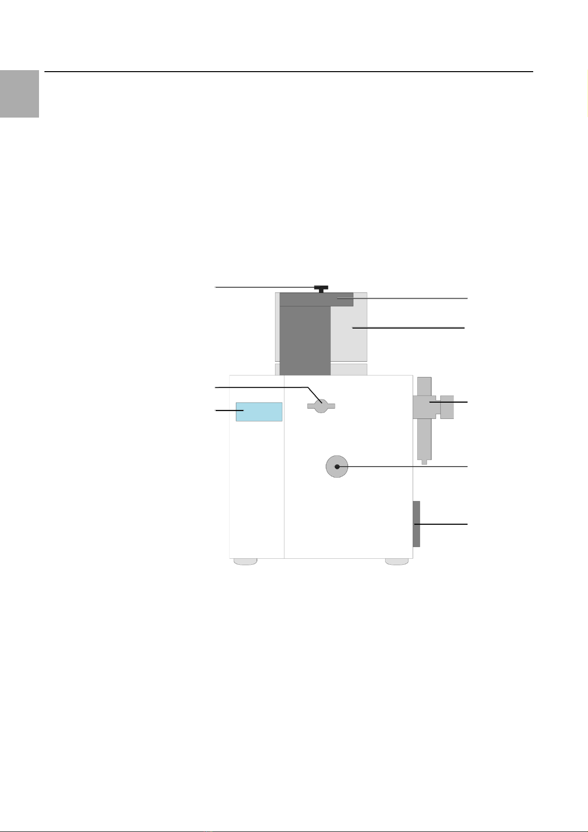
3Device description................................................................... 6
3.1 Overview...............................................................................................................6
3.2 Technical data.......................................................................................................7
4Operating instructions............................................................. 8
4.1 Setting up the machine........................................................................................8
4.2 Switch on the machine ........................................................................................9
4.3 Menus...................................................................................................................9
4.4 Conductor insertion / conductor cutting..........................................................11
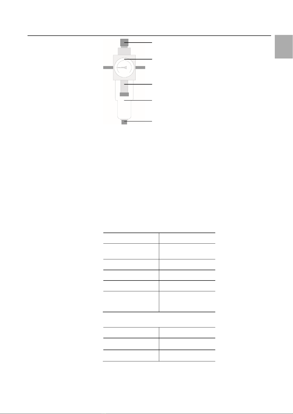
5Tools......................................................................................12
5.1 Ferrule feed........................................................................................................12
5.2 Triggering unit....................................................................................................13
5.3 Insulation stripping blade and cam...................................................................13
6Maintenance .........................................................................14
6.1 Maintenance notes............................................................................................14
6.2 Daily maintenance..............................................................................................14
6.3 Weekly maintenance .........................................................................................15
6.4 Monthly maintenance........................................................................................18
6.5 Quarterly maintenance......................................................................................21
6.6 When required...................................................................................................22
7Troubleshooting.....................................................................22
7.1 Machine does not start......................................................................................22
7.2 No start for inserted wire..................................................................................22
7.3 The wire is only stripped....................................................................................23
7.4 Large number of rejects.....................................................................................23
7.5 Error messages...................................................................................................23
8Pneumatic connection diagram ..............................................26
9Electrical connection diagram.................................................27
10 Spare parts ............................................................................28
11 Disposal.................................................................................28

1 About this documentation
Rittal Crimping machine L8 We reserve the right to make technical modifications. 3
EN
1About this documentation
The warnings in this documentationare structured differently depending on the
severity of danger.
Warning!
Possible risk of fatality!
Notices with the signalword "warning" warn you about situations
which could leadto fatal or serious injuries if you do not pay attention
to the notices specified.
Caution!
Risk of injury!
Notices with the signalword "caution"warn you aboutsituations
which could leadto injury if you do notpay attentionto the notices
specified.
Attention!
Propertydamage!
Notices with the signalword "attention"warnyou aboutdangers whichcould
resultin damage to property.
Situation-related warnings may contain the following warning symbols:
Symbol
Meaning
Warning: dangerous electrical voltage
Warning: injury to hands due to sharp blades
Work may only be performed by a qualified electrician
Only perform work with personal protective equipment
Disconnect the mains plug
Notes on documentation
Additionalformattingis usedin the restof the textwhich has the followingmean-
ing:
Note:
This constitutes information which is not related to safety,but which
provides importantinformation regarding correctand effectivework.
◼This symbol indicates an "action point"and showsthatyou shouldperform an
operation or procedure.

2 General safety instructions
4 We reserve the right to make technical modifications. Rittal Crimping machine L8
EN
–Bullet points are indicatedwith dashes.
Operating instructions in other languages can be foundon our website:
Click here!
2General safety instructions
2.1 Intended use
The crimping machineL8 is an electro-pneumaticcrimping machinedesigned ex-
clusively forstripping insulation from flexibleconductors in accordancewith
DIN 60228:2005 and for crimping loose wireendferrules with plastic collars (size
0.5 –2.5 mm² / length 8). For this reason, because of its construction, the machine
has only this intended use.
For the intendeduse,the following mustbe observed:
–All notes from the operating instructions
–The documentation of the supplied products,as well as
–The notes for servicing/maintenance
Any other use is deemed improper.
The details in section 3.2 "Technical data" as well as in the original documentation
for any accompanying supplied products must be observed and adhered to.
An improperuse of the productis notknownto the manufacturer.
The manufacturer isnot liable forany damage resultingfrominappropriateor un-
intended use.
2.2 The following is not permitted
–Removing notification or warning signs.
–Openingthe machineduring operation.
–Using the machine with obvious defects or damage.
–The insertion of objects thatare notconductors.
2.3 Machine dangers
A risk evaluation with subsequent safety inspection and safety acceptance was per-
formed on the crimping machineL8.
2.4 Operational hazards
The operator may rectifyonly thosefaultsfor which the housing doesnot need to
be removed.
◼The machine mustbe disconnected fromthe power gridbeforechanging tools or
spare parts.
2.5 Hazardsources
◼Before performing servicing, maintenanceand cleaning workon the machine,
switch off the machine, disconnectitfromthe power supply (e.g.cutoff the elec-
tricity supply, switch off the fuse).

2 General safety instructions
Rittal Crimping machine L8 We reserve the right to make technical modifications. 5
EN
Caution!
Risk of injury due to missing safety equipment!
◼Never removesafety equipment or decommissionitby making
changes to the machine.
2.6 Safety equipment
Safety equipment is installed to protectpersonnel. The operating company is
obliged to inspectthe safety devicesannually.
–Housing: Afterremoval of the housing, ensurethatthe earthing wireisinserted
before the machineisclosed again. The housingmay be removed onlyby special-
ists or qualified personnel.
–Switched-mode powersupply: The SMPS protects against dangerous voltages,
because not morethan 60 VACor 110VDC may be present.
Under no circumstancesmay safety devicesbe changed, removed orcircumvented
by changes to the machine.
2.7 Warning signs at and on themachine or components
–PE conductorconnection: This marking is placed on theearth screw.
Symbol
Meaning
The protective earth is a measure that in the event of a fault protects
against dangerous touch voltage and electrical shock. The "protective
earth" measure is provided by the protective conductor.
The connectionismade viaan IEC connector with leadingprotective conductor
contact.The "PE"protectiveconductor(green/yellowinsulating sheathonly in
Germany) is used for these protective measures.
2.8 Residualrisks
Even when all safety and warning notes areobserved,residualrisks remain forthe
machine operation.
The machine is state-of-the-artand builtaccording to recognisedsafety regula-
tions. Nevertheless, hazards forusers or third-parties can result when operating
the machine.
–The machine may be usedonly forthe intended purpose.
–The machine mustbe in propersafety condition during commissioning.
Warning!
Electrical shock causedby working on live components!
◼Only authorised personnel may performworkon electronic
components.
2.9 Safety measures at theinstallationsite
The machine mustbe placed stableon atable.
–There is alarge hazard risk should amachinefall.
Note:
Inner-companyinstructions and checks should ensure thatthe work-
place and itsvicinity remainclean and uncluttered.
2.10 Notes for the operating company
–The operatingcompanyis obligedto write operatinginstructions.
–The operatingcompanyis obligedto inspectthe safetydevices annually.

3 Device description
6 We reserve the right to make technical modifications. Rittal Crimping machine L8
EN
–Deploy only original fuses with the specifiedamperage.
–Knowledgeof the local, operational safety and accident-preventionregulations.
–All notes on machinesmustbe keptlegible, and renewedwhennecessary.
◼Notify the manufacturer without delay shoulddefects becomeapparent, provid-
ed they were notcausedintentionally.
◼Any imperfect machineparts must be replaced immediately.
2.11 Noise
The A-weightedequivalent continuous soundpressure level of the L8 crimpingma-
chine is ≤70 dB(A).
Consequently, earmuffs are not requiredfor operating the machine.
3Device description
3.1 Overview
Fig. 1: Overall view
5
4
2
1
3
6
8
7

3 Device description
Rittal Crimping machine L8 We reserve the right to make technical modifications. 7
EN
Fig. 2: Interior view
Key
1Setting button
2Separating unit
3Vibrating conveyor (VC) upper part
4Touch display
5Twist lock
6Maintenance unit
7Insertion funnel
8Mains filter module
9Opening wedge
10 S1 setting
11 Stripped insulation scrap container
12 Hexagonal spanner
13 Tool unit (ferrule holding unit, crimping unit)
14 Cable feeding unit
3.2 Technical data
AS crimping machine L8
Feeding length
27 mm + crimping length
Cross-section
0.5…2.5 mm² (20…14 AWG)
Crimping form
Trapezoidal
Drive
Electro-pneumatic
Voltage
100…240 V
Frequency
50/60 Hz
Power consumption
100 VA
Fuse (mains filter module)
2 x T2AH250V
Operating pressure
5.5 bar
Air consumption per cycle
approx. 0.9 l
10
11
9
12
13
14

4 Operating instructions
8 We reserve the right to make technical modifications. Rittal Crimping machine L8
EN
AS crimping machine L8
Degree of protection
IP 20
Cycle time
approx. 1.0 s
Continuous sound pressure level
≤70 dB(A)
Dimensions (W x D x H)
390 x 330 x 460 mm
Colour
RAL 9003
Weight
31 kg
Interfaces
Touch display
Operating environment
Storage/transport temperature
-25 °C…+55 °C
Ambient temperature
+5 °C…+40 °C
Operating temperature
+10 °C…+45 °C
Max. operating altitude
2000 m above mean sea level
Humidity
50% at 40 °C (without dewing)
90% at 20 °C (without dewing)
Contamination level
2
Pressure safety equipment
85%…110 %
4Operating instructions
4.1 Setting up the machine
◼Read the operatinginstructions carefully beforecommissioningthe machine.
◼Deploy the machine onlyin adry environment.
Attention!
The electricaldatashown on the rating plate must match thatofthe powergrid.
Otherwise, damagecan occur to the machine.
Warning!
Electrical shock causedby working on live components!
◼Disconnectthe mains plug and separatethe machinefromthe
pneumatic network.
Note:
◼Before processing,clean the stranded wires toremovelubricants
(e.g.talcum).
The machine is equipped with a compressed-airmaintenance unit (compressed-air
filter and regulatingvalve). Itcan be connecteddirectlyto the compressed-airsup-
ply.
◼Connectthe mains cableto the machineand to the powersupply.

4 Operating instructions
Rittal Crimping machine L8 We reserve the right to make technical modifications. 9
EN
Fig. 3: Maintenanceunit
Key
1Setting button
2Manometer
3Filter element
4Container
5Manual drain
4.2 Switch on themachine
◼Switch on the mains switch atthe mains filter module.
Menu 1 appears in the display.
4.3 Menus
–Up or down
–SelectE
Operating menu
Ready/Strip/Crimp
VC: %
Status display
Vibrating conveyor (VC)
power
Day quantity count
(C 5 s: delete)
Error message
First number
Second number
S: 1/0 (step)
Stripping-crimping
Feed
Vibrating conveyor(VC) power
Display in %
Increase power
Decrease power
–120 V: VC power approx. 54%
–230 V: VC power approx. 27%
1
2
3
4
5

4 Operating instructions
10 We reserve the right to make technical modifications. Rittal Crimping machine L8
EN
◼SelectE.
Cursor flashes.
◼Setthe value with .
◼ConfirmE.
To load the infeedbelt:
–When the key isheld down, the VCvalue increases tothe highestvalue.
–After releasingthe key, the VC power returns after 3 seconds to the storedVC
value.

4 Operating instructions
Rittal Crimping machine L8 We reserve the right to make technical modifications. 11
EN
Insulation stripping program
0
Stripping and crimping
1
Stripping only
After switchingon themachine, the "Stripping = 0"programis set.If the "Stripping
= 1" program is selected, this is displayed in the Operating menu.
Quantity counterand processing time
Tot. ct.:
Total quantity count
Mach. time:
Machining time of a cycle
in ms
Service:
Shows the quantity still to
be processed until the next
service.
Testinputs
No., status
I or 0
Name of the component
Testoutputs
No., status
I or 0
Name of the component
For simulating:
C = 0, E = 1
General data
Step times
PC data
Language
1: German
2: English
3: French
4: Italian
5: Dutch
4.4 Conductor insertion / conductor cutting
Insertingthe conductorin the insertionfunneltriggers the workcycle.
Note:
The cable mustbe cutstraightand mustnothave any kinks orbends.

5 Tools
12 We reserve the right to make technical modifications. Rittal Crimping machine L8
EN
40 mm
Correct
Incorrect
Correct
Inclined cut
Incorrect
Protected
conductor
Pulled-out
conductor
Crushed
conductor
Recessed
conductor
Tab. 1: Conductorinsertion/ conductorcutting
5Tools
5.1 Ferrule feed
The ferrulefeed consistsof the vibratingconveyorupperpart,the separatingunit
and the feed pipe.
◼Loosen the screwin the middleof the vibrating conveyorupperpart,turn it
counter-clockwiseand raiseitfor changing.
◼To set the separatingunit,pull the buttonupwardsand turn.
◼Fasten the vibrating conveyorupperpartagain.
◼Fill the wire end ferrules.
◼Call program2 "Vibrating conveyorpower".
◼To load the infeedbelt:press the key until the required powerof the vibrating
conveyoris attained and keeppressed.
After releasingthe key, the powerreturns to the storedvalue.
◼Setthe feed speed so thatan adequatesupplywith ferrules is guaranteed.
The first wire is only strippedof its insulation.
Wire end ferrule
Vibrating conveyor (VC)
upper part
Separating unit
0.5 / 8 N
1
0.5
0.5 / 8 S
1
0.75 –1.0
0.75 / 8 N
1
0.75 –1.0
0.75 / 8 S
1
0.75 –1.0

5 Tools
Rittal Crimping machine L8 We reserve the right to make technical modifications. 13
EN
Wire end ferrule
Vibrating conveyor (VC)
upper part
Separating unit
1.0 / 8 N
1
0.75 –1.0
1.0 / 8 S
1/2
1.5
1.5 / 8 N
1/2
1.5
1.5 / 8 S
2
2.5
2.5 / 8 N
2
2.5
2.5 / 8 S-XS
2
2.5
Tab. 2: Setting overview
5.2 Triggering unit
◼Open the frontpanel.
◼Pull the tool unit forwards.
◼Place the setting wheel of the triggering unitatposition "0","+","–" or "––".
–"0" is the standard feeding length.
–"+" lengthens the feeding length (turnclockwise).
–"–"shortens the feeding length.
–"––" shortens the feeding lengthmore to prevent stranded-wire protrusion
(turn counter-clockwise).
Fig. 4: Setting the triggering unit
5.3 Insulationstripping blade and cam
Caution!
There is risk of fingerinjuries atthe insulationstripping blades.
◼Never touch theblade.
◼Remove the fastening screws(2x).
◼Remove the cam.
◼Remove the cover.
◼Remove the bladewith tweezers.
◼Install in the reversesequence.

6 Maintenance
14 We reserve the right to make technical modifications. Rittal Crimping machine L8
EN
Dependingon the strength and thicknessof the insulation,the cammustbe ad-
justed in the "+"or "–" direction.
◼To cutless,move the camin the "+"direction;to cutmore,movethe camin the
"–"direction.
Fig. 5: Insulation stripping module
6Maintenance
Warning!
Electrical shock causedby working on live components!
◼Disconnectthe mains plug and separatethe machinefromthe
pneumatic network.
6.1 Maintenance notes
Note:
–The manufacturer recommends thatacustomer serviceis per-
formed on the machine every 400,000 cycles.
–Never cleanthe machineinteriorwith compressed air.
–Do notuse spray oil or spray grease.
–If possible, use silicone or PTFEoils (Teflon oil).
–Use lubricating greases suitablefor rollerbearings and sliding sur-
faces.
–The display and the touch screenare madeof plastic and mustnot
come into contactwith hard objects.The touch-screen surfacecan
be cleanedwith a softcloth without any solvents.
6.2 Daily maintenance
Emptying the stripped insulationscrapcontainer
◼Open the frontpanel.
◼Withdrawand empty the stripped insulation scrap container.
◼Reinsertthe container.
◼Close the frontpanel.
Cam

6 Maintenance
Rittal Crimping machine L8 We reserve the right to make technical modifications. 15
EN
Fig. 6: Stripped insulationscrap container
Key
1Stripped insulation scrap container
6.3 Weekly maintenance
Blowingclean the feed guide
◼Remove the feed guide:unscrewthe handle,turn the guide counter-clockwise
and remove upwards.
◼Remove the feeding material fromthe feed guide.
◼Clean the guide carefullywith compressedair.
◼Replace the guide on themachine, turnclockwiseto the limitstop and tighten
the fastening handle.
Fig. 7: Feed guide
Key
1Handle
2Feed guide
1
1
2

6 Maintenance
16 We reserve the right to make technical modifications. Rittal Crimping machine L8
EN
Cleaning the machineinterior
◼Open the frontpanel.
◼Remove the strippedinsulationscrap container.
◼Clean the machineinteriorusing abrushand a vacuumcleaner.
Attention!
Propertydamage!
Do notuse compressedair to clean the machineinterior.
Cleaning the stranded wirefixture
◼Clean the strandedwirefixtureusing abrush and methylatedspirits.
Fig. 8: Stranded wire fixture
Key
1Cleaning area
2Stranded wire fixture
Cleaning the holding pliers
◼Open the frontpanel.
The holding pliersare locatedon the frontpanel.
◼Clean the holding pliersusing abrush.
1
2

6 Maintenance
Rittal Crimping machine L8 We reserve the right to make technical modifications. 17
EN
Fig. 9: Holding pliers
Key
1Holding pliers
Cleaning the insulationstripping unit
◼Swivel the tool unit to the right.
◼Clean the entry holein the insulation strippingunitcarefully with asoft,suitable
brush (e.g.pipe cleaner) and methylatedspirits.
◼Under no circumstances,lubricate the insulationstrippingunit.
Fig. 10: Insulation stripping unit
Key
1Cleaning area
Checking the insulationstrippingblade
◼Swivel the tool unit to the right.
◼To visually check the blade forwearor damage,pushthe stripping carriageup-
wards.
◼To resetthe bladesetting:Pushthe tool unitrightto the limitstop.
1
1

6 Maintenance
18 We reserve the right to make technical modifications. Rittal Crimping machine L8
EN
Fig. 11: Insulation stripping unit
Key
1Control area
2Limit stop
3Stripping carriage
Checking the compressed areasetting
To ensurecorrect functioningof the machine,the pressuresetatthe maintenance
unit mustlie in the range 5.0 to 5.5 bar.
Fig. 12: Compressed-air maintenanceunit
Key
1Pressure setting
6.4 Monthly maintenance
Stranded wirefixture
◼Check the strandedwire fixturecastorsforfreemovement.
◼Lightly oil the castors pivot.
◼Lightly oil the strandedwire fixturepivot.
1
2
3
1

6 Maintenance
Rittal Crimping machine L8 We reserve the right to make technical modifications. 19
EN
Fig. 13: Stranded wire fixture
Key
1Stranded wire fixture pivot
2Castor
Holdingpliers
◼Lightly oil the holding pliers atthe pivotand the contactsurface.
Fig. 14: Holding pliers
Key
1Pivot and the contact surface
Ferruleholding unitand crimping tool
◼Swivel the tool unit to the right.
◼Loosen the rightscrew of the strandedwire fixtureby half aturn.
◼Hit the screwheadlightly.
◼Remove the rightscrewcompletely.
◼Withdrawthe stranded wirefixtureatthe front.
◼Ensure thatthe distance ring remains on the shaft.
◼Pull the tool unit forwards.
◼Check the ferrule holding unitcastors for free movement.
1
2
1
1

6 Maintenance
20 We reserve the right to make technical modifications. Rittal Crimping machine L8
EN
◼Check the crimpingtool castors forfree movement.
◼Lightly oil the castors pivot.
◼Lightly oil the guide pin.
◼Reinsertthe stranded wirefixture. Ensurethatthe guide shaftsits in the hole of
the stranded wirefixture.
◼Tighten the right screw.
Fig. 15: Ferrule holding unitand crimping tool
Key
1Right screw
Fig. 16: Ferrule holding unitand crimping tool
1
2
3
4
5
1
This manual suits for next models
1
Table of contents
Popular Crimping Tools manuals by other brands

TE Connectivity
TE Connectivity PRO-CRIMPER III instruction sheet

JAE
JAE ET-KN01W-12 Operation manual

Textron
Textron Klauke K 16 instruction manual

Tyco Electronics
Tyco Electronics AUTOPRESS C120 Technical handbook

Tyco Electronics
Tyco Electronics PRO-CRIMPER III instruction sheet

RYCO
RYCO MINI CRIMPER Series Operation manual