Gates MobileCrimp 4-20 Installation manual


Carefully read and understand the following warnings before operating this crimper.
WARNING!
An incorrect hose assembly can rupture or blow apart in use, resulting in serious injury, death
or property damage. REMEMBER: Others depend on you to make correct assemblies.
FOR SAFETY
’
S SAKE
USE THIS MACHINE ONLY IF YOU:
1. Receive hands-on TRAINING with the MobileCrimp®4-20 and Gates assemblies.
2. Follow current GATES OPERATING MANUAL AND CRIMP DATA for the MobileCrimp 4-20.
3. Use only NEW (UNUSED) GATES hose and fittings.
4. Wear SAFETY GLASSES.
5. KEEP HANDS CLEAR OF MOVING PARTS. Support hose with one hand while activating
pump with other hand.
6. DO NOT operate pump UNLESS cylinder is locked in crimp position.
7. To avoid risk of injury, DO NOT use crimper UNLESS CONTROLLER BASE PLATE is in place.
8. DO NOT operate crimper in horizontal position.
Shop Air Pump
Prod. No.: 7481-0002, Part No.: 77820
Weight: 10 lbs.
1/4 H.P. 12 Volt DC Pump
Prod. No.: 7481-0037, Part No.: 77439
Weight: 20.5 lbs.
1/2 H.P. 115 Volt AC Pump
Prod. No.: 7481-0034, Part No.: 77441
Weight: 32 lbs.
Hand Pump
Prod. No.: 7481-0006, Part No.: 77821
Weight: 25.6 lbs.
1/4 H.P. 115 Volt AC Pump
Prod. No.: 7481-0033, Part No.: 77440
Weight: 20 lbs.
1-1/2 H.P. 115 Volt AC Pump
Prod. No.: 7481-0035, Part No.: 77442
Weight: 108 lbs.
Positive Stop Control
Prod. No.: 7480-0051, Part No.: 77421
Dimensions: 12 1/4" wide x 6 1/4"deep x 19 1/2" high
Weight: 57 lbs. (with stand)
Digital Dial Control
Pump Specifications
All pumps maximum rated working pressure: 10,000 psi
®
4
2
0
MobileCrim
p
®

1
Contents
Identification List ...........................................................................................2
Setup ..............................................................................................................3
Hose Preparation ............................................................................................7
Operating Instructions ....................................................................................9
Measuring and Adjusting the Crimp Diameter ..............................................13
Maintenance .................................................................................................14
Troubleshooting ............................................................................................15
Replacement Parts List ..................................................................................16
Warranty ................................................................................inside back cover
Serial No. _______________
(Located on front top of cylinder)
Date of Purchase _________
®
4
2
0
MobileCrim
p
®
1
®
4
2
0
MobileCrim
p
®
2
Die
Pressure Plate
Hose Assembly
Literature Packet Magnet
.05 Allen Wrench
Clamps
Stand
Molykote and Brush
Crimper
Identification List
3
®
4
2
0
MobileCrim
p
®
Setup
1. Unpack carton.
• Remove crimper, pressure plate (1),
nylon-covered hose assembly (1),
literature envelope (1), stand (2 pieces),
magnet (1) .05 Allen wrench (1) and
Molykote lubricant (1) from shipping
carton. Locate the serial number
assigned to the crimper on the top front
of the cylinder and record on page one
for future reference.
2. Attach crimper to the stand.
• Place crimper on flat, well-supported
surface (such as the top of a workbench
or the bed of a service vehicle) with the
handle to the right.
• Remove two (2) knobs, flat washers (2)
and spacer (1) from crimper pivot bolts.
• Slide the two halves of the stand
together and attach to the crimper
at the pivot bolts.
• Replace spacer, flat washers and knobs.
Do not tighten knobs.
• Lift crimper and allow stand to swing
down onto the surface. Tighten knobs.
Left Side
Right Side
spacer

®
4
2
0
MobileCrim
p
®
4
3. Fasten crimper to work surface
before use (to avoid damage to
machine or personal injury because
an unsecured machine can fall).
• Position crimper so that mounting holes
are approximately 7" to 8" from the
edge of the work surface.
• Mark the drilling location using the
mounting holes as a guide (see illustra-
tion below).
• Drill two 5/16" diameter holes.
• Use mounting holes or clamps to fasten
stand to work surface.
4. Attach pump to crimper.
• Place pump near crimper.
• Connect hose assembly to the pump
port (3/8" NPT threads). Pipe sealant
may be used to seal connection. (For
best connection, use Gates’ Quick
Disconnect couplings, G95311-0606
and G95321-0606, sold separately.)
• Connect opposite end to the adapter
on crimper.
5. Check pump oil level.
• Pump comes with oil in reservoir.
• Check proper oil level per pump
operating manual instructions or the
Maintenance Section (p. 14) of this
manual.
6. Connect pump to power outlet.
• For 115V connection, plug power cord
into a properly grounded and rated circuit
(see inside cover for circuit requirements).
• For vehicle battery connection, see
pump operating manual.
Edge of
work
surface
(2) 5/16 "diameter holes
71
/2"11"
clamps
mounting holes
To avoid damage to
the machine or injury
to you, ALWAYS fasten
the crimper to the work
surface before you attempt to crimp.
5
®
4
2
0
MobileCrim
p
®
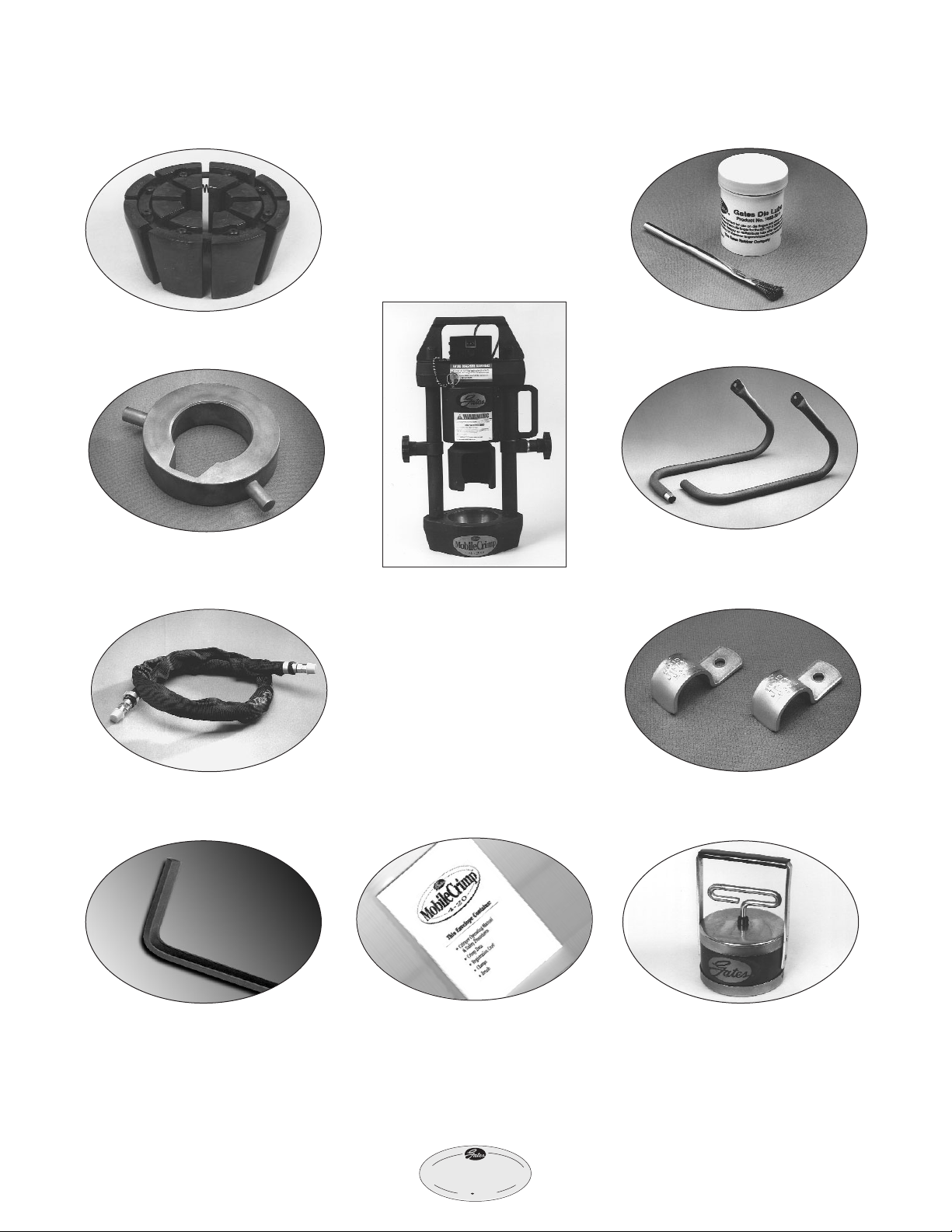
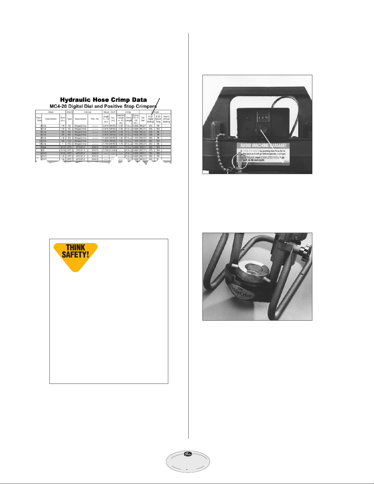
7. Bleed air from system.
• Tilt crimper forward so adapter is at
its highest point.
• Turn the knob on the controller to a
setting of 400, which allows the ram
to extend approximately 1".
• Turn pump on by pressing and holding
the power ”on“ switch, (see pump
operating manual for switch location)
which extends the ram.
• When the light comes on and buzzer
sounds, immediately release “on” switch
allowing ram to fully retract. NOTE: If
light and buzzer are faint or do not
work, the controller batteries may need
replacement. See “Maintenance” section
of this manual.
• Repeat a minimum of five (5) times to
bleed air completely.
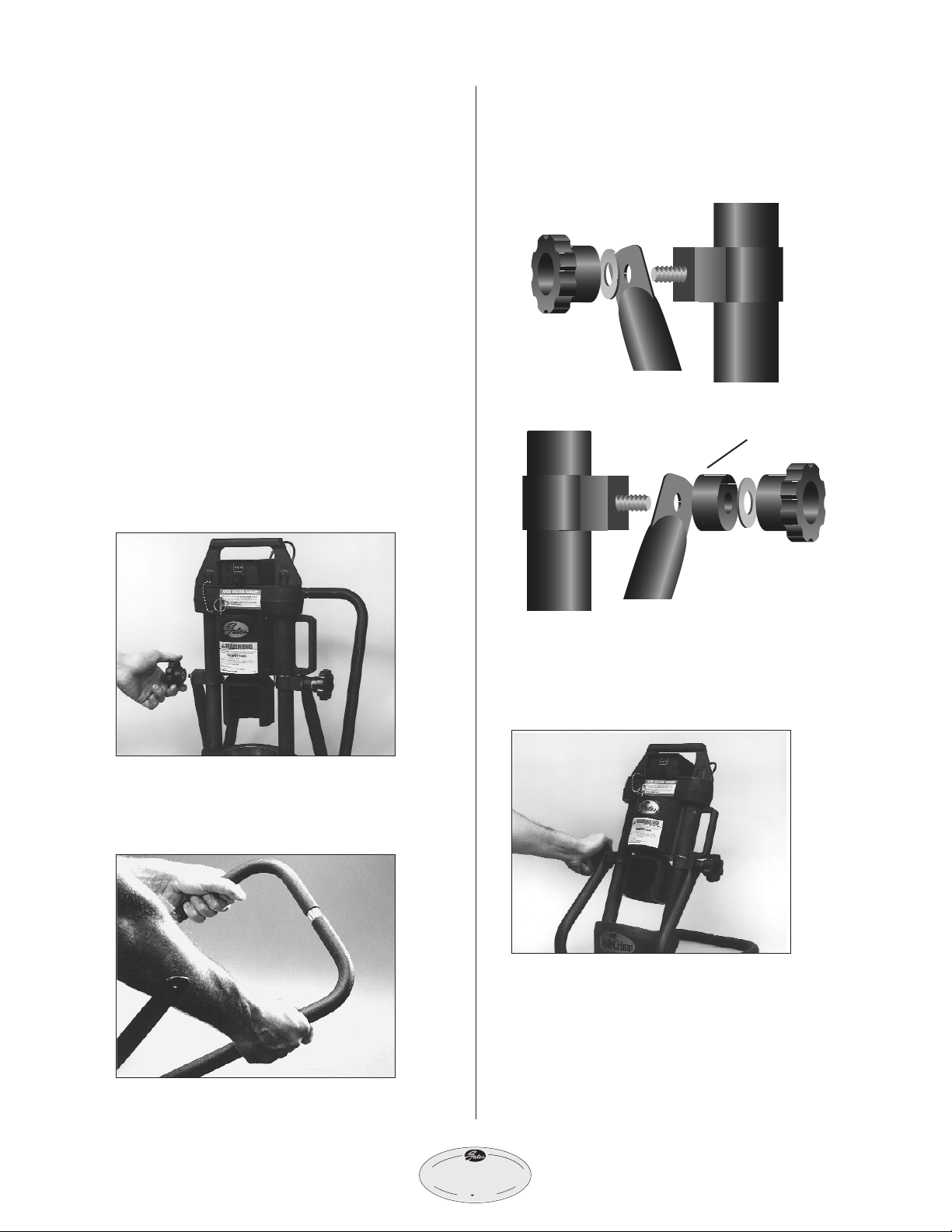
8. Place crimper in comfortable
working position.
• See photo below for suggested working
position.
IMPORTANT
Do not operate crimper in
horizontal position because dies
will become unstable.
Note: It’s a good
idea to place a rub-
ber mat on the floor
near the crimper to
reduce the chance of damaging a
die if dropped and improve opera-
tor comfort.
CAUTION
Keep away from all moving parts!
If bodily contact with a moving
part occurs, immediately release
the pump power “on“ switch.

®
4
2
0
MobileCrim
p
®
6
9. Calibrate.
• Before crimping a hose assembly,
check calibration.
Calibration is the proper relationship between
a setting and the crimp diameter. It should be
checked at least monthly, possibly weekly or
daily, if crimper has been used heavily or
abused.
• Place the MC33 die set into the
die cone and install pressure plate.
• Turn the knob to a setting of 245.
Note: Rotating the knob on front of switch box clockwise will
increase the number; counterclockwise will decrease the num-
ber. When changing the setting, always move to a highter
number then down to the desired setting. (Example: To change
from 200 to 245, move dial up to 300 then down to 245.)
• Insert an 8G MegaCrimp®coupling into the
die set.
• Complete the crimp.
• Remove the coupling and measure the crimp
diameter, which should measure 1.000"
±.003". To properly measure crimp diameter,
refer to page 13.
• If the crimp diameter is within this range, no
adjustment is necessary.
• If the crimp diameter is not within this range,
the crimper must be calibrated.
• To get a smaller crimp diameter,
change the setting to a smaller number.
• To get a larger crimp diameter,
change the setting to a larger number.
• For every .001" change in crimp diameter,
change the setting by 002. For example, to
increase the crimp diameter by .002", increase
your setting from 245 to 247.
• Turn the knob to this new setting
and crimp a new coupling.
• After the correct diameter is achieved, pull the
plastic cap from the knob.
• Loosen the two (2) set screws in the brass knob
1/4 to 1/2 turn using a .05” Allen wrench.
• Turn the brass knob either clockwise or coun-
terclockwise to get the setting back to 245.
• Tighten the set screws and replace
the plastic cap.
• Crimper is now calibrated.

7
®
4
2
0
MobileCrim
p
®
Hose Preparation
MegaCrimp®Pre-Assembled
Couplings.
1. Cut hose to desired length.
2. Using Gates crimp data chart #35019
(Ind), 428-7365 (Auto), select the
correct coupling or visit our website
to download our electronic program
at www.gates.com/ecrimp.
3. Place a visible mark on hose cover
at the insertion length shown on the
crimp data chart.
4. Insert coupling into the hose until
the mark lines up with the end of
the coupling ferrule.
5. Hose and coupling are now ready
for crimping.
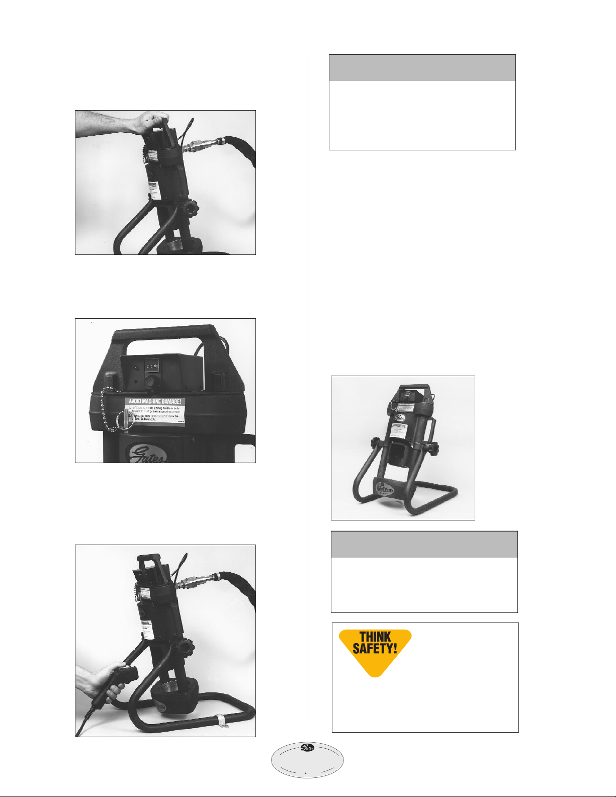
CAUTION
A new hose and end fittings
must be used when building a
hose assembly. Re-using any
components will seriously
affect performance and could
result in serious injury or
property damage.
®
4
2
0
MobileCrim
p
®
8
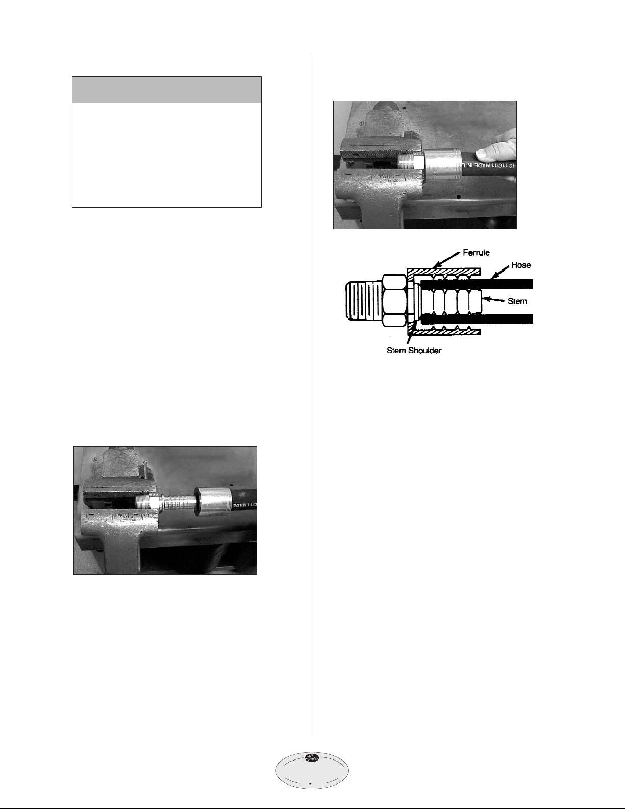
GlobalSpiral™Two-Piece Couplings.
1. Cut hose to desired length.
2. Using Gates crimp data chart #35019
(Ind), 428-7365 (Auto), select the
correct stem and ferrule or visit our
website to download our electronic
program at www.gates.com/ecrimp.
3. Place ferrule over end of hose.
4. Lubricate the first two or three
serrations on stem with lightweight
oil (SAE 10W).
5. Clamp stem in vise on hex portion,
and push hose onto stem.
Hose should be flush against stem
shoulder (see cutaway drawing below).
6. Hose and coupling are now ready
for crimping.
CAUTION
A new hose and end fittings
(stem/ferrule) must be used
when building a hose assembly.
Re-using any components will
seriously affect performance and
could result in serious injury or
property damage.
9
®
4
2
0
MobileCrim
p
®
Operating
Instructions
1. Select correct die set.
• Using Gates crimp data chart
#35019 (Ind), 428-7365 (Auto) or
ecrimp, select correct die set for the
hose and coupling being crimped.
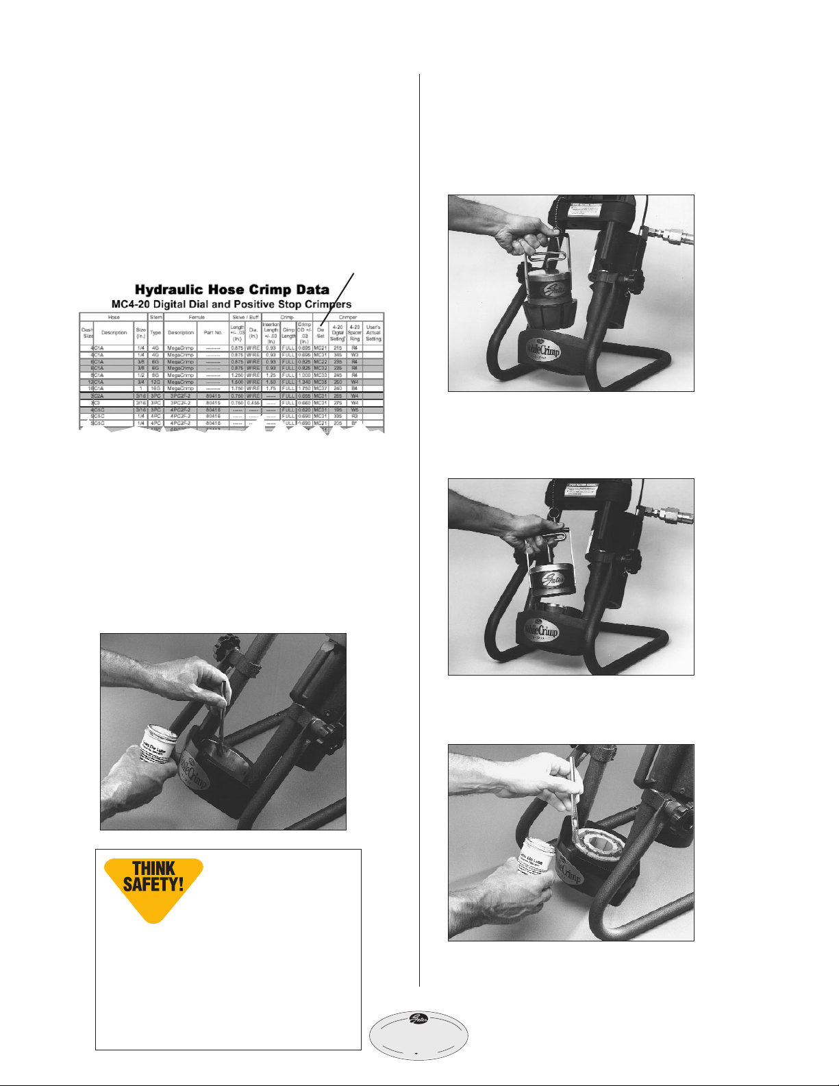
2. Lubricate and load die.
• Swing cylinder to ”die loading” position.
• Apply thin layer of Molykote* lube
to the inside surface of the die cone.
Re-apply lube whenever surface
becomes shiny.
• Using the magnet, place the die set
into the die cone.
• Remove magnet by lifting the ”T”
handle, making sure the top of the
die fingers are even.
• Apply a thin layer of Molykote lube
to the top of the die set.
* Use only Gates Molykote lube for proper operation
or Gates-recommended grease.
die set
Important Note:
Lubricants should be
reapplied to metal-to-
metal sliding surfaces
whenever the surface becomes shiny.
Failure to do this reduces the life of
the dies and cone. Excessive wear on
these components produces poorly
performing hose assemblies that
could blow apart and result in injury.
10
3. Select correct setting.
• Using Gates crimp data chart #35019
(Ind), 428-7365 (Auto) or ecrimp, select
correct setting for the hose and coupling
being crimped.
• Settings are approximate and may
need to be adjusted. See Measuring
and Adjusting the Crimp Diameter
Section (p. 13).
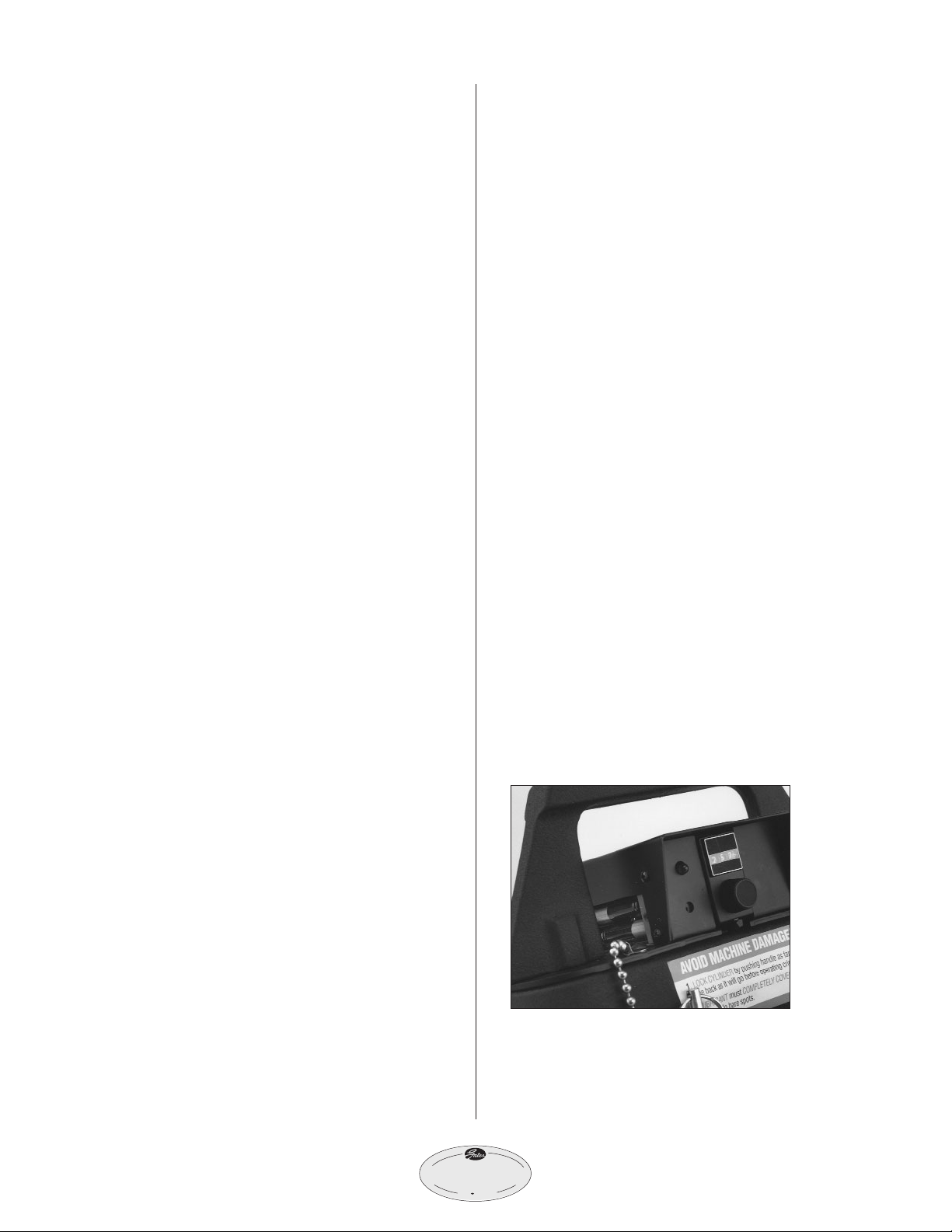
4. Dial in setting and install
pressure plate.
• Turn the knob on the controller to
the selected setting.
• If crimping multiple assemblies, move
the locking switch to the right to hold
the setting. Moving switch to the left
allows the setting to be changed.
•Place the pressure plate onto the die set.
locking switch
setting
IMPORTANT
SAFETY NOTE:
All settings are approxi-
mate! Machining toler-
ances exist for each crimper, die set
and supporting piece of equipment
which will affect your actual setting.
Always check the crimp diameter to
ensure that it is within the published
limits. Record your actual crimper
setting to achieve the specified
crimp diameter for future use.
Failure to heed this message could
result in improperly made assem-
blies, blowing the hose out of the
fittings at high pressure, and risk of
fire and/or serious injury.
®
4
2
0
MobileCrim
p
®

11
®
4
2
0
MobileCrim
p
®
5. Insert hose assembly.
• Insert assembly from the bottom of the
die cone up through the die set.
• Locate the top of the ferrule
approximately 1/16"below the
top of the die set.
• When crimping bent tube and block-style
couplings, keep thread end aligned with
notch in pressure plate.
6. Swing cylinder into crimping
position.
• Using the handle, swing cylinder
toward you and lock into place with
lock pin.
IMPORTANT
For GS couplings, make sure
the top of the ferrule rests
against the hex or round
shoulder of the coupling.

12
®
4
2
0
MobileCrim
p
®
• Make sure cylinder is locked into posi-
tion by placing lock pin into hole on
top of cylinder.
7. Begin the crimp.
• Start pump by steadying hose with one
hand while pressing and holding
the power “on”switch with the other
hand, which extends the ram (see pump
operation manual for switch location).
• When light comes on and buzzer
sounds, immediately release the power
“on” switch. Crimp is now complete.
NOTE: If light and buzzer become faint
or do not work, the controller batteries
may need replacement. See Maintenance
Section (p. 14).
8. Remove hose assembly.
• While holding hose, lightly lift bottom
of die set to release hose assembly.
• Remove hose assembly.
Serious injury and/or crimper
damage can result if the cylinder
is not locked in its crimp position.
IMPORTANT
lock pin
Keep away from all moving parts!
If bodily contact with a moving part
occurs, immediately release the pump
power “on“ switch.
Incorrect Correct
CAUTION
13
Measuring and
Adjusting the
Crimp Diameter
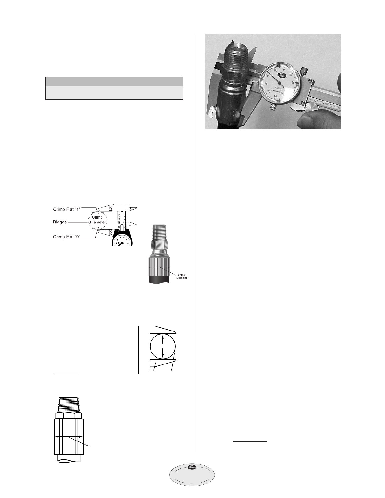
1. Measure the crimp diameter.
When using 21 and 22 Dies
• Using Gates “21/22” dial calipers
(Product No. 7369-1320, Part No. 78217)
measure halfway between ridges (Fig. 1).
To be sure crimp diameter is being
properly measured, mark a crimp flat.
Beginning with that flat, count 9 flats to
get the diameter. Be sure caliper blades
DO NOT touch ridges. (See Photo 3.)
• Measure halfway between
the ends of crimped portion
of the ferrule (Fig. 2).
When NOT using 21 and 22 Dies
• Using Gates dial calipers (Product No.
7369-0320, Part No.
78215) which are
notched to clear ridges,
measure halfway
between ridges (Sketch
1). Be sure caliper fingers
DO NOT touch ridges or
part number stamps.
(See Photo 3.)
• Measure halfway
down the crimped
portion of the ferrule
(Sketch 2).
2. Check crimp diameter.
• The measured crimp diameter must be
within 0.010"of the published crimp
diameter. If not, the hose assembly
cannot be used, and adjustment will
be required.
3. Adjust the crimp diameter
(if necessary).
• Check top of die set and the surfaces
of the pressure plate for any debris
(metal chips, dirt, etc.). Debris may
cause some variation in crimp diameter.
• If necessary, clean the surfaces and
lightly lubricate with Molykote.
• If the machine is properly calibrated,
a slight adjustment to the crimp setting
can be made.
• To get a smaller crimp diameter,
change the setting to a smaller number.
• To get a larger crimp diameter,
change the setting to a larger number.
• For every .001"change in crimp diameter,
change the setting by 002. For example,
to increase the crimp diameter by .002",
increase your setting from 245 to 247.
• After the correct diameter is achieved,
record this new setting on your crimp
data chart for future reference.
4. Multiple crimps.
• When crimping multiple assemblies,
check every tenth crimp to ensure
diameter is within acceptable range
(± 0.010").
DO NOT measure on top of part number stamps.
NOTE:
FIG. 1
CRIMP DIA.
CALIPER RIDGES
SKETCH 1
CRIMP
DIA.
SKETCH 2
FIG. 2
PHOTO 3
®
4
2
0
MobileCrim
p
®
Maintenance
This crimper requires minimal maintenance.
However, the following practices are
recommended to ensure maximum
reliability and service.
Lubricate.
• Using the small brush and Molykote,
apply a light coat to the inside surface
of the die cone whenever it becomes
shiny.
Check oil level.
• Check the hydraulic oil level in the
pump reservoir after each 10 hours of
use (see pump operation manual for
instructions).
• If the oil is more than 1/2" below the
top, add a high-grade hydraulic oil, such
as Mobil DTE 25, until within 1/2" of
the top of the reservoir.
Change the oil.
(NOTE: Frequency depends on the pump
’
s
general working conditions, severity of use
and overall cleanliness.)
• For general shop conditions, change
oil every 300 hours. For field/mobile
conditions, more frequent changes are
required.
• Drain, clean and refill the reservoir
per pump operating instructions with
a high-grade hydraulic oil, such as Mobil
DTE 25 until within 1/2" of the top of
the reservoir.
Inspect die sets and pressure plate.
• Periodically inspect the surfaces of die
sets and pressure plate for debris (metal
chips, dirt, etc.) or damage.
• If debris is present, clean and lightly
lubricate. If damaged, replacement is
required (see parts list for ordering
information).
• Inspect the die links, springs and
shoulder screws monthly to see if they
are broken, cracked or missing. These
conditions may affect crimp quality.
Replace if necessary.
Inspect hose assembly.
• Inspect hose assembly connecting the
crimper and pump monthly (more often
with severe use).
• Check nylon sleeve for cuts or abrasion.
• If sleeve is damaged, check hose for
damage.
• If hose has any signs of damage, replace
immediately. A damaged hose may rup-
ture and cause serious injury.
• If hydraulic oil is present on the hose
assembly, serious damage may exist.
Replace immediately.
Battery replacement.
• If light and buzzer become faint or do
not work, batteries may need replacement.
The controller uses two (2) AAA batteries.
• Remove the two (2) screws located
on the lower left side of the controller.
• Remove the side cover and the batteries
from their holder.
• Replace the batteries and position
as shown on the holder.
• Replace and secure the side cover.
®
4
2
0
MobileCrim
p
®
14

Troubleshooting
All equipment is tested for proper perfor-
mance before it is shipped from the factory.
However, if you experience any difficulties,
check the list below to help restore equip-
ment to proper operating standards.
15
®
4
2
0
MobileCrim
p
®
Problem Correction
• Ram will not fully extend.
• Ram will not retract.
• Pump motor will not start.
• Setting will not change.
• Light and buzzer do not work.
• Check hydraulic oil level in pump reservoir.
• Hydraulic oil temperature must be within
+40º F and +120º F.
• Unplug pump from electrical outlet.
(WARNING: pump must be unplugged
to avoid risk of injury.)
• Slowly and carefully loosen hose at pump.
Be prepared to catch oil as it escapes. If
ram retracts, pump valve may be stuck or
need replacement.
• Check electrical connections.
• Locking switch may be engaged.
Move switch to the left.
• Replace the controller batteries. See
Maintenance Section.
• Replace controller.
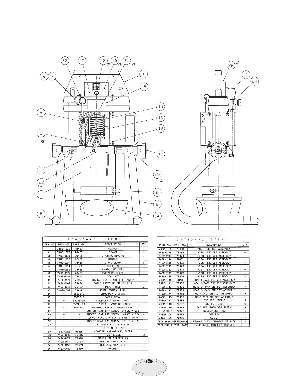
Replacement
Parts List
* Not shown
16
®
4
2
0
MobileCrim
p
®

®
4
2
0
MobileCrim
p
®
Notes

®
4
2
0
MobileCrim
p
®
Notes
Table of contents
Other Gates Crimping Tools manuals

Gates
Gates GC96 User manual

Gates
Gates GC16XD Installation manual

Gates
Gates GC32TSi Guide

Gates
Gates GC32-XD User manual

Gates
Gates MCX50 Use and care manual

Gates
Gates Power Crimp 707 Installation manual

Gates
Gates MC3001 Use and care manual

Gates
Gates GC16XD Installation manual

Gates
Gates GC20 Instruction Manual

Gates
Gates GC32FLEX Guide


