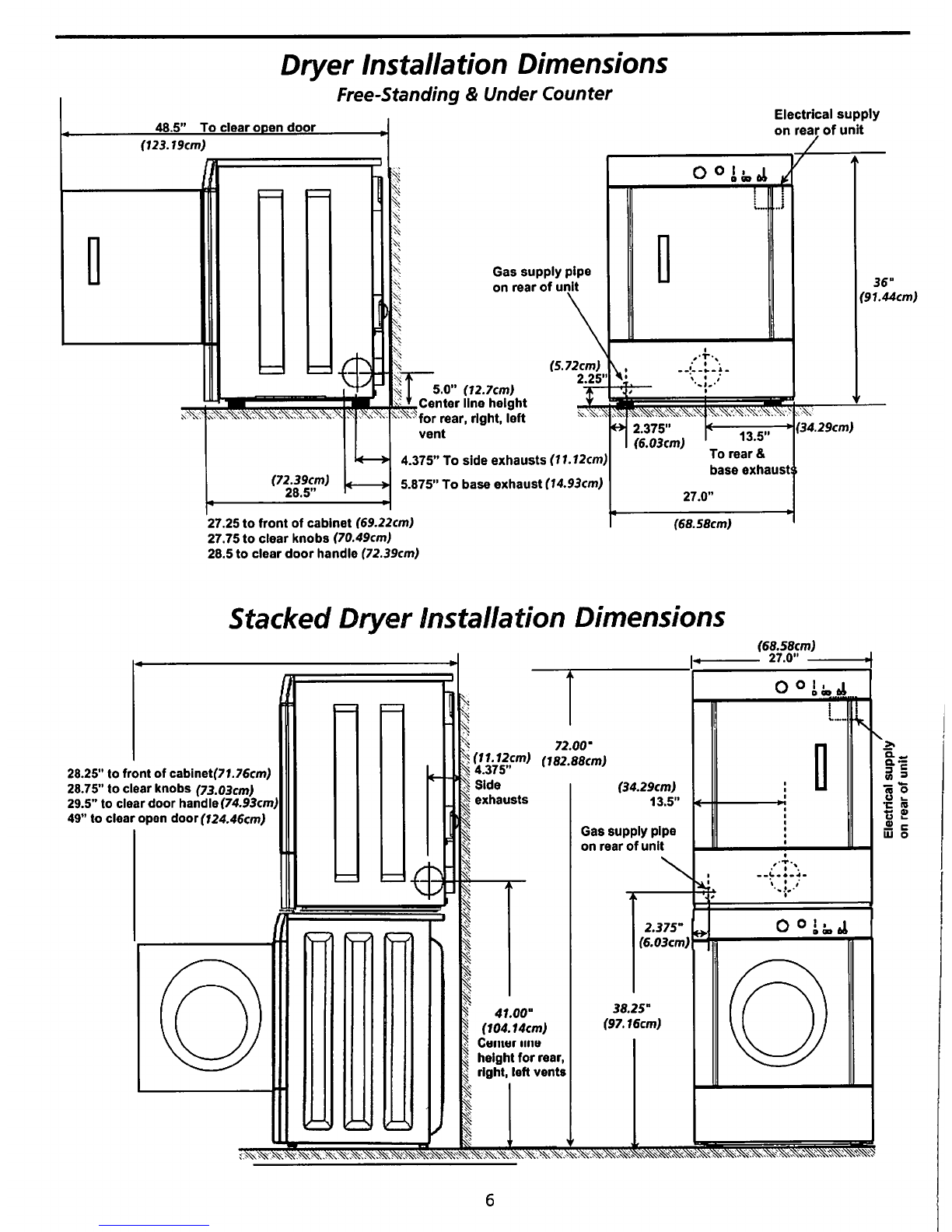
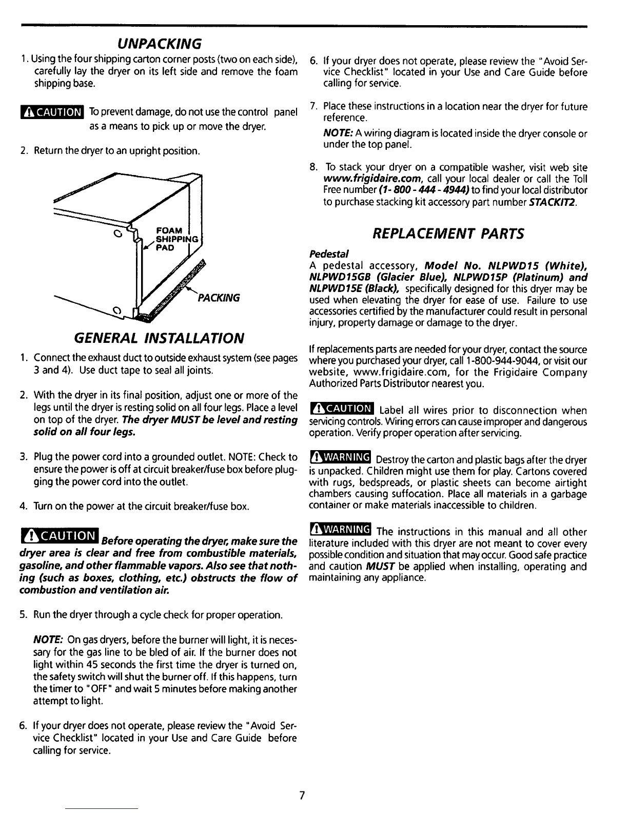
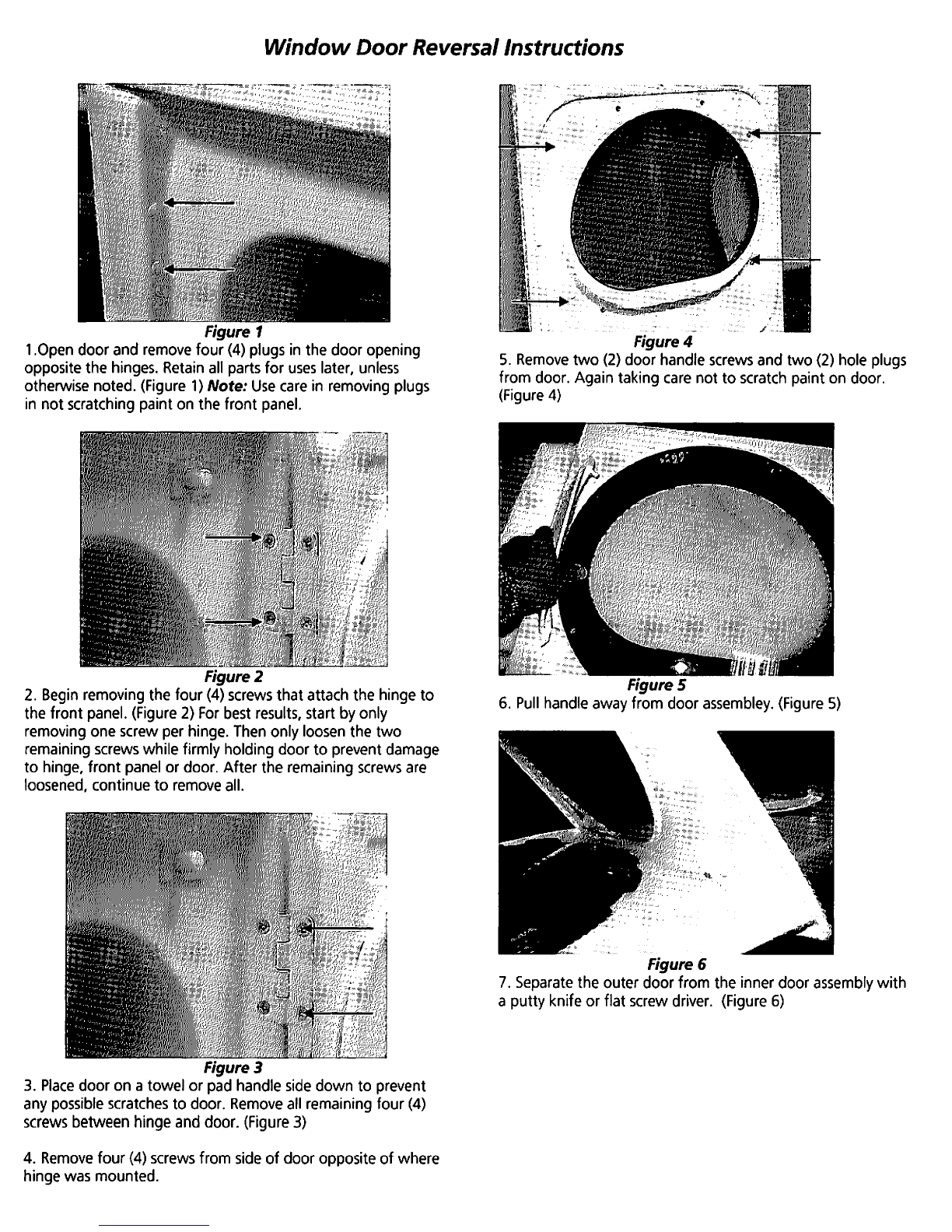
Frigidaire Gas & Electric Dryer User manual
Other Frigidaire Dryer manuals

Frigidaire
Frigidaire Affinity FAQE7001LB User manual

Frigidaire
Frigidaire GLGR642AS5 User manual

Frigidaire
Frigidaire 137101400 User manual

Frigidaire
Frigidaire 137135100B User manual

Frigidaire
Frigidaire GLEQ332CAS2 User manual

Frigidaire
Frigidaire FARE4044MW Owner's manual

Frigidaire
Frigidaire GLEQ642CAS2 Quick start guide

Frigidaire
Frigidaire FFRE1001PW0 User manual

Frigidaire
Frigidaire Affinity FAQG7072L R Owner's manual

Frigidaire
Frigidaire GLGQ332CA User manual

Frigidaire
Frigidaire AEQ6700FS - 27" Electric Dryer User manual

Frigidaire
Frigidaire AEQB7000E User manual

Frigidaire
Frigidaire Affinity FAQE7011L User manual

Frigidaire
Frigidaire GLEH1642FS - 3.1 cu. Ft. Laundry Center User manual

Frigidaire
Frigidaire AGQ6700FE - 27" Gas Dryer User manual

Frigidaire
Frigidaire FGR311FS - 27" Gas Dryer User manual

Frigidaire
Frigidaire FEQBB30DS0 User manual

Frigidaire
Frigidaire 134420700A User manual

Frigidaire
Frigidaire Affinity FASE7073LA Installation instructions

Frigidaire
Frigidaire FDEB34RG User manual


Popular Dryer manuals by other brands

Bosch
Bosch WTA79200GB Installation and operating instructions

Amana
Amana W10233410A Use and care guide

Miele
Miele TWH 780 WP operating instructions

Asko
Asko T760 user guide

Alliance Laundry Systems
Alliance Laundry Systems 25 Series Original instructions

Bosch
Bosch Logixx 10 WTB76556GB Instruction manual and installation instructions


Indesit
Indesit IDV 75 instruction manual

Infiniton
Infiniton SD-DG85C manual

BOMANN
BOMANN WT 5019 instruction manual

Alliance Laundry Systems
Alliance Laundry Systems TMB795C Installation

Asko
Asko T793C operating instructions

Kenmore
Kenmore 8041 - 5.8 cu. Ft. Capacity Electric Dryer installation instructions