FRONIUS VR 4040 Guide

VR 4040 Operating Instructions
Spare Parts List
/ Battery Charging Systems / Welding Technology / Solar Electronics
Wire Feeder
EN
42,0426,0014,EN 002-30032012


3
EN
DEAR FRONIUS CUSTOMER
This brochure is intended to familiarise you with how to operate and
maintain your VR 4040 unreeling device. Es liegt in Ihrem Interesse, die
Bedienungsanleitung aufmerksam zu lesen und die hier angegebenen
Weisungen gewissenhaft zu befolgen. Sie vermeiden dadurch Störun-
gen durch Bedienungsfehler. Your machine will repay you by giving you
constant operational readiness and absolute reliability for many years to
come.
FRONIUS INTERNATIONAL GMBH
Warning! The VR 4040 unreeling device may only be operated
by trained personnel, and only in accordance with the technical
directions. When using the machine, you must follow the instruc-
tions given in the "Safety rules".
COPYRIGHT
Copyright to this instruction manual remains the property of Fronius
International GmbH.
Text and illustrations are all technically correct at the time of going to
print. The right to effect modifications is reserved. The contents of the
instruction manual shall not provide the basis for any claims whatever on
the part of the purchaser. If you have any suggestions for improvement,
or can point out to us any mistakes which you may have found in the
manual, we should be most grateful for your comments.
CONTENTS
Dear Fronius Customer ............................................................................ 3
Fronius International GmbH ................................................................ 3
Copyright ............................................................................................... 3
Safety rules................................................................................................ 4
General remarks ................................................................................... 4
Obligations of owner/operator ............................................................. 4
Obligations of personnel ...................................................................... 4
Utilisation for intended purpose only .................................................. 4
Informal safety precautions ................................................................. 4
Safety precautions at the installation location .................................. 4
Safety precautions in normal operation, and for the operator ......... 4
Spares / wearing parts and accessories ............................................ 4
Safety measures for maintenance, inspection and troubleshooting 5
Modifications to the VR 4040 unreeling device ................................. 5
Particular danger spots ........................................................................ 5
Protective features ............................................................................... 5
Transport ............................................................................................... 5
Personal protective equipment ........................................................... 5
Hazards from noxious gases and vapours ........................................ 5
Hazards from flying sparks, radiation and heat ................................ 5
Keep all solvent vapours well away from the arc radiation. ............ 5
Hazards from welding current ............................................................. 5
General remarks ....................................................................................... 6
Machine concept ................................................................................... 6
Areas of application, and features ...................................................... 6
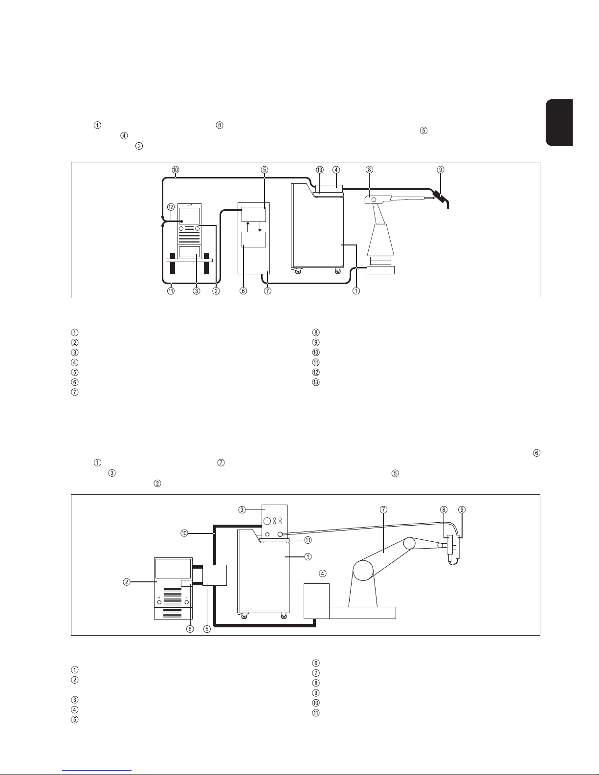
Practical examples ................................................................................... 7
Configuration 1: MIG/MAG welding .................................................... 7
Configuration 2: TIG cold-wire welding .............................................. 7
Start-up ...................................................................................................... 8
Accessories ........................................................................................... 8
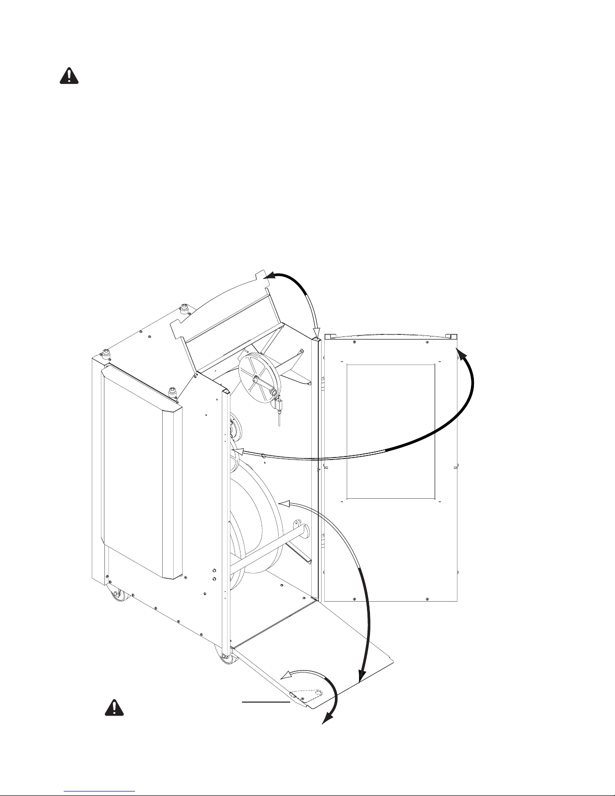
Opening and closing the VR 4040 unreeling device ........................ 8
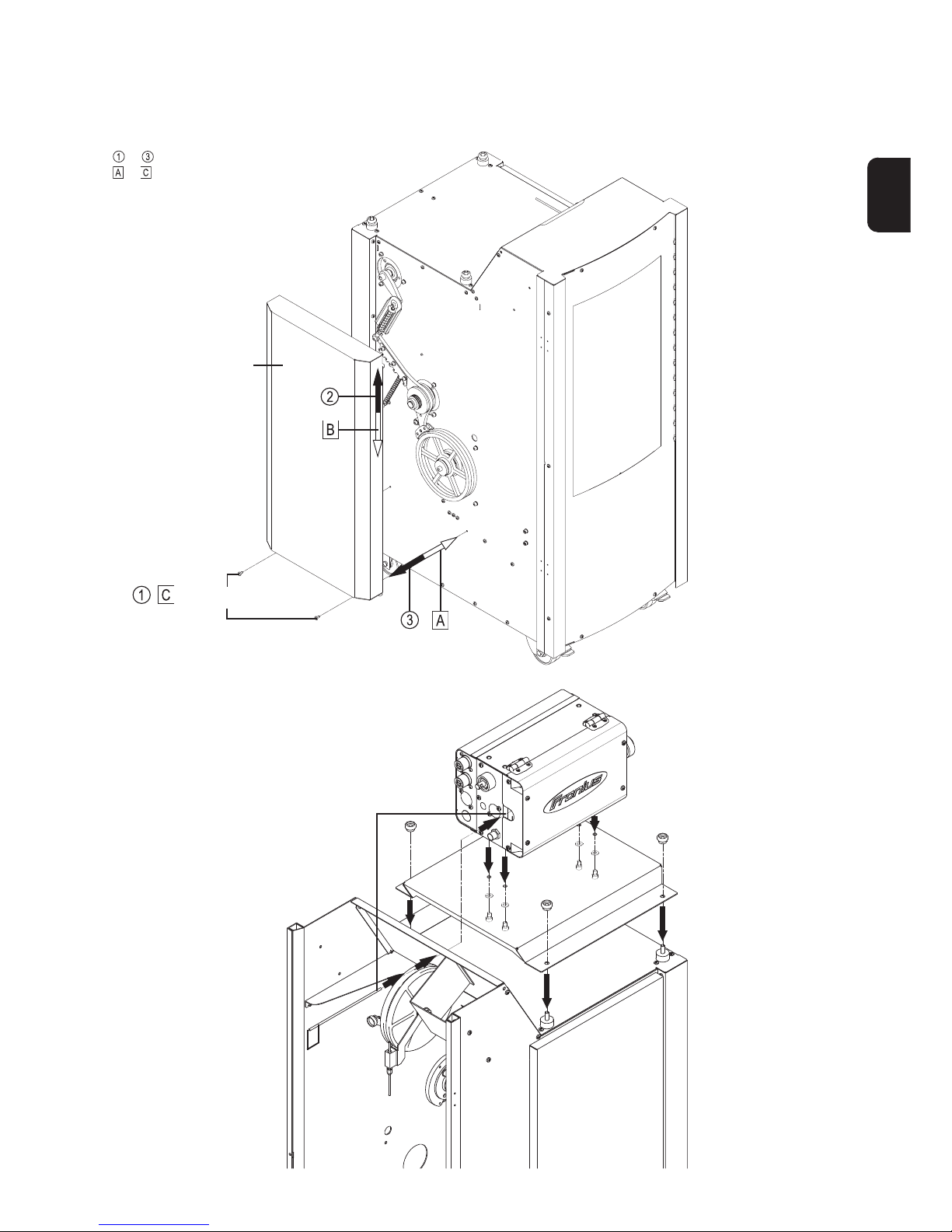
Dismounting and re-mounting the side guard panel......................... 9
Mounting the wirefeeder ...................................................................... 9
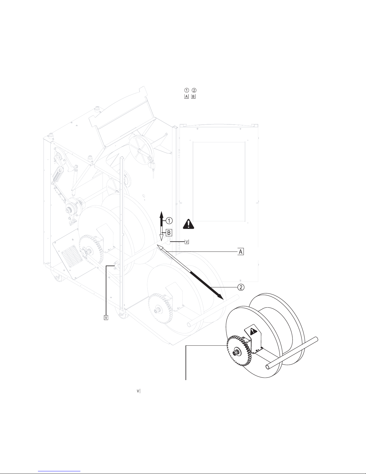
Removing and inserting the wire-spool carrier................................ 10
Mounting and dismounting the wire-spool driver ............................ 11
Fastening the wire-spool carrier to the Spool and detaching
it from the Spool ................................................................................. 11
Inserting the welding wire .................................................................. 12
230 V interior heating system, unregulated ..................................... 13
Mounting the interior heating system ............................................... 13
24 V interior heating system, regulated ........................................... 14
Mounting the interior heating system ............................................... 14
End-of-wire watchdog ........................................................................ 16
Mounting the end-of-wire watchdog ................................................. 17
Functional principle ................................................................................ 19
Idling..................................................................................................... 19
Accelerating......................................................................................... 19
Equilibrium, and working position ..................................................... 20
Decelerating ........................................................................................ 20
Adjusting the braking system ................................................................ 21
Adjusting the braking force ................................................................ 21
Adjusting the braking system response ........................................... 21
Adjusting the working position .......................................................... 22
Measuring the value for the wire tensile-force limitation ............... 22
Setting the wire tensile-force limitation ............................................ 23
Troubleshooting guide ............................................................................ 24
Care, maintenance and inspection ....................................................... 25
General remarks on the wearing parts ............................................. 25
Function test ........................................................................................ 25
Damper ................................................................................................ 26
Brake block .......................................................................................... 27
Brake clearance .................................................................................. 27
Overload coupling ............................................................................... 28
Wire-guide tubes................................................................................. 30
Drawback pulleys................................................................................ 31
Shoe for end-of-wire watchdog ......................................................... 32
Disposal of used parts and materials ................................................... 33
Technical Data ......................................................................................... 33
EC-Declaration of Conformity
Spare parts list
Circuit Diagram

4
SAFETY RULES
GENERAL REMARKS
The VR 4040 unreeling device has been made in
accordance with the state of the art and all recognised
safety rules. However, faulty or improper operation may:
- endanger the operator or third parties
- adversely affect the welding machine or other property of the owner’s
- make it difficult or impossible to work efficiently with the VR 4040
unreeling device.
All persons involved with the start-up, operation, inspection and
maintenance of the VR 4040 unreeling device must:
- be suitably qualified,
- be knowledgeable and skilled in welding,
- observe the instructions given in this manual and
- follow exactly all accident prevention and environmental protection
rules, both those that are generally applicable and any local/national
rules
Where other persons are nearby while the machine is in operation, you
must:
- inform them about these dangers,
- provide them with suitable protective equipment and/or:
- erect protective partitions and/or safety curtains.
It’s your safety that’s at stake!
OBLIGATIONS OF OWNER/OPERATOR
The owner/operator undertakes to ensure that the only
persons allowed to work with the VR 4040 unreeling
device are persons who
- are familiar with the basic regulations on workplace
safety and accident prevention and who have been
instructed in how to operate the VR 4040 unreeling
device
- have read and understood the sections on “safety rules” and the
“warnings” contained in this manual, and have confirmed as much
with their signatures
Regular checks must be performed to ensure that personnel are still
working in a safety-conscious manner.
OBLIGATIONS OF PERSONNEL
All persons entrusted with carrying out work on (and with)
the VR 4040 unreeling device shall undertake
- to observe the basic regulations on workplace safety
and accident prevention
- to read the sections on “safety rules” and the “warnings” contained
in this manual before they start work with the unit, and to sign to
confirm that they have understood these
UTILISATION FOR INTENDED PURPOSE
ONLY
The VR 4040 unreeling device may ONLY be used for
unreeling the welding wire from wire spools.
Utilisation for any other purpose, or in any other manner, shall be deemed
to be "not in accordance with the intended purpose". The manufacturer
shall not be liable for any damage resulting from such improper use.
Utilisation in accordance with the “intended purpose” also comprises
- following all the instructions given in this manual
- performing all stipulated inspection and servicing work
INFORMAL SAFETY PRECAUTIONS
- The instruction manual for the VR 4040 unreeling
device must be kept at the machine location at all
times.
- In addition to the instruction manual, copies of both the
generally applicable and the local accident prevention and
environmental protection rules must be kept on hand, and of course
observed in practice.
- All the safety instructions and danger warnings on the VR 4040
unreeling device itself must be kept in a legible condition.
SAFETY PRECAUTIONS AT THE
INSTALLATION LOCATION
- The VR 4040 unreeling device must be placed on an
even, firm floor in such a way that it stands firmly. The
swivel castors of the integral trolley must be locked,
both in the steering direction and in the direction of
travel.If the VR 4040 unreeling device were to roll
away on its own or topple over, it could easily injure or
even kill someone!
- It is not permitted to operate the VR 4040 unreeling device in rooms
that are at risk from fire and/or explosion.
- Ensure that the workplace and the area around it are always kept
clean and tidy.
- When choosing a location for the VR 4040 unreeling device, make
sure that it is easily accessible for the operator, and for maintenance
and inspection.
- The VR 4040 unreeling device is designed for indoor use only. It is not
permitted to set it up or operate it outdoors.
SAFETY PRECAUTIONS IN NORMAL
OPERATION, AND FOR THE OPERATOR
- Only operate the VR 4040 unreeling device if all its
protective features are fully functional.
-If any of the protective features are faulty, the VR 4040
unreeling device must not be started up or operated in any way.
- Do not bypass, damage or remove any of the protective features
- Any malfunctions that might impair safety must be put right immediately
- Ensure that:
- the swivel castors are locked, both in the steering direction and in
the direction of travel
- the side guard panel is mounted
- the VR 4040 unreeling device is kept closed while it is running
SPARES / WEARING PARTS AND
ACCESSORIES
- Use only original spares and wearing parts. With parts
sourced from other suppliers, there is no certainty
that these parts will have been designed and
manufactured to cope with the stressing and safety
requirements that will be made of them.
- When ordering, please state the Fronius part number
(as given in the spare parts list), and the serial number
of your unit.
- Use original Fronius accessories only
- The following accessories are available:
- Wirefeeder
- Feeder set
- Spool set
- Interior heating system
- End-of-wire watchdog

5
EN
SAFETY MEASURES FOR MAINTENANCE,
INSPECTION AND TROUBLESHOOTING
- Do not perform any maintenance, inspection or trou-
bleshooting work while the VR 4040 unreeling device
is running.
- Only remove guard panels or other safety features if the
Operating Instructions specifically instruct you to do so, and only to
the extent that is absolutely necessary
- Be aware of the increased risk!
- Ensure that nobody can be endangered in any way
- When performing maintenance and inspection work, or troubleshooting
and function-testing, follow the safety precautions prescribed for
normal operation wherever possible.
MODIFICATIONS TO THE VR 4040
UNREELING DEVICE
- Do not make any alterations, additions or modifications
to the VR 4040 unreeling device without first obtaining
approval from the manufacturer.
PARTICULAR DANGER SPOTS
- Do not touch the rotating toothed wheels, drawback
pulleys and rotating wire-spool inside the VR 4040
unreeling device.
- For this reason, only operate the VR 4040 unreeling device when the
cover is closed, the swing-out ramp is folded back up into place, the
door is closed and the side guard panel is mounted.
- The angular edged parts of the VR 4040 unreeling device also
present a certain risk of injury.
PROTECTIVE FEATURES
Isolating:
- Protective cover over toothed wheels
- Side guard panel
- Cover
- Door
- Swing-out ramp + latch
Non-isolating:
- Locking mechanism for the swivel castors of the integral trolley
- Earthing of the optional interior heating system (the VR 4040 unreeling
device itself must not be earthed)
- The insulated spokes and overall design of the drawback pulleys
TRANSPORT
- The packed VR 4040 unreeling device is supplied on
a Europallet
- The VR 4040 unreeling device is not suitable for
being transported by crane hook or any other such
hoisting appliance
- When unpacked, the machine can be transported with the aid of its
integrated trolley
- If the machine is transported (unpacked) by fork-lift truck, never
insert the fork beneath the longitudinal axis of the VR 4040 (i.e. with
the door or rear wall facing the fork-lift truck)
PERSONAL PROTECTIVE EQUIPMENT
For your personal safety, take the following precautions:
- Wear stout footwear that will also insulate even in wet
conditions
- Protect your hands by wearing insulating gloves
- Protect your eyes from UV rays with a safety shield containing
regulation filter glass
- Wear flame-retardant clothing that covers your whole body
- Where high noise levels are encountered, use ear-protectors
HAZARDS FROM NOXIOUS GASES AND
VAPOURS
- Extract all fumes and harmful gases away from the
workplace, using suitable means.
- Ensure a sufficient supply of fresh air.
HAZARDS FROM FLYING SPARKS,
RADIATION AND HEAT
-KEEP ALL SOLVENT VAPOURS WELL
AWAY FROM THE ARC RADIATION.
- Move all combustible objects well away from the welding location.
- Welding must NEVER be performed on containers that have had
gases, fuels, mineral oils etc. stored in them. Even small traces of
these substances left in the containers are a major explosion hazard.
- Special regulations apply to rooms at risk from fire and/or explosion.
Observe all relevant national and international regulations.
HAZARDS FROM WELDING CURRENT
- An electric shock can be fatal. Every electric shock is
hazardous to life.
- The magnetic fields generated by high amperages
may impair the functioning of life-critical electronic
devices (e.g. heart pacemakers). Users of devices
such as these must take medical advice before going
anywhere near welding workplaces
- All the welding cables on the welding equipment that is being used
must be firmly attached, undamaged and properly insulated. Replace
any loose connections and scorched cables immediately.

6
GENERAL REMARKS
MACHINE CONCEPT
The VR 4040 unreeling device is a further member of the modular family
of Fronius wire-feeding equipment.
Suitable adapters are available for mounting whatever wirefeeder unit is
used. There are also suitable adapter sets for fitting a wide range of
different types of wire spool.
In designing the unreeling device, Fronius paid particular attention to
ergonomic issues. Special emphasis was placed here on making it easier
to change the wire spools, which can often be very heavy. A removable
wire-spool carrier facilitates spool changeover. If a second wire-spool
carrier is mounted, this can save even more down-time by making it easy
to prepare a second spool ready for insertion.
The swing-out ramp and the guide-rails make it possible to change the
wire spool easily, quickly and with a minimum of physical effort. The large
viewing panel allows users to check constantly on the operational status,
and on how much wire there is left on the spool (N.B. this latter point can
also be monitored by the optional end-of-wire watchdog).
The optional end-of-wire watchdog alerts the operator in good time to the
fact that the wire spool will soon need changing. This makes it possible
to prevent unnecessary disruption of the production process. If the
unreeling device is used in locations with strong temperature fluctuations
and high atmospheric humidity, we advise ordering the optional interior
heating system. The interior heating system practically rules out any risk
of condensation inside the unit, and so prevents any quality-impairing
oxidation from taking place on the welding wire.
AREAS OF APPLICATION, AND FEATURES
The VR 4040 unreeling device is specially designed for robot and
automated applications. Both in MIG/MAG welding and in TIG (and laser)
cold-wire welding, the VR 4040 unreeling device is a vital component of
any precision, high-performance wirefeed system.
The unreeling device is ideal for wire spools with a mass of up to 80 kg,
a diameter of up to 500 mm and a width of up 250 mm. Increases in the
permissible spool mass are possible on request.
The high-dynamism concept underlying the VR 4040 unreeling device
makes possible both high wirefeed speeds and high wire-spool weights,
at the same time as ensuring that the welding wire is only exposed to a
minimum of tensile strain. Even when welding starts up at high wirefeed
speeds, the wire buffer prevents the spool-mass from accelerating
jerkily, meaning that the wire is exposed to only moderate tensile forces.
During welding start-up, the tensile force of the wire is only increased (as
a function of the wirefeed speed) as far as is necessary in order to
achieve timely acceleration of the wire spool.
Although the unreeling device has been optimally preconfigured for a
wide range of different wire spools, wirefeed speeds and welding wires
before leaving the factory, it is possible to “fine-tune” it where needed.
The following key parameters can be adjusted:
- braking force of the wire-spool brake
- braking system response
- working position
- limitation of wire tensile force in the acceleration phase
N.B.! For a detailed explanation of how the braking system works, and
of how to adjust it, please see the sections headed “Functional principle”
and “Adjusting the braking system”.
Fig.1 VR 4040 unreeling device
In order to provide greater flexibility at the welding location, the unreeling
device comes with an integral trolley consisting of two fixed castors and
two swivel castors. The swivel castors can be locked, both in the steering
direction and in the direction of travel. If one side of the unreeling-device
housing needs to be placed flush against a wall or an adjacent machine,
the VR 4040 can also be ordered in a “mirror-image” version.

7
EN
Fig.2 Configuration 1 - VR 4040 combined with the TS 4000 / 5000 or TPS 4000 / 5000 power source and the VR 1500 wirefeeder
unit
Legend:
...... VR 4040 unreeling device
...... TS 4000 / 5000 or TPS 4000 / 5000 MIG/MAG power source
...... FK 4000 / FK 4000 R cooling unit
...... VR 1500 MIG/MAG wirefeeder unit
...... ROB 4000 / 5000 robot interface
...... Robot control
...... Robot control cubicle
PRACTICAL EXAMPLES
The examples given below also apply, analogously, to applications using
automatic welding equipment.
CONFIGURATION 1: MIG/MAG WELDING
In the configuration example shown in Fig.2, the VR 4040 unreeling
device is combined with an industrial robot , the VR 1500 MIG/MAG
wirefeeder unit and a TS 4000 / 5000 or TPS 4000 / 5000 digital MIG/
MAG power source .
In this example, the power source communicates with the robot via the
ROB 4000 / 5000 robot interface .
...... Robot
...... Welding torch
...... Interconnecting cable
...... LocalNet connection cable
...... “LocalNet passive” splitter
...... Wirefeeder mounting adapter
In the configuration example shown in Fig.3, the VR 4040 unreeling
device is combined with an industrial robot , the KD 7000 TIG cold-
wire feeder and a MagicWave 2600 / 2600 CEL or TransTig 2600 CEL
/ 3000 TIG power source .
The power source communicates with the robot via the robot interface
(for MagicWave 2600 / 2600 CEL and TransTig 2600 CEL / 3000) and the
TIG-KD connection box (robot control is networked with the power
source and the KD 7000).
Fig.3 Configuration 2 - VR 4040 combined with the MagicWave 2600 / 2600 CEL or TransTig 2600 CEL / 3000 power source and the KD 7000 cold-wire feeder
Legend:
...... VR 4040 unreeling device
...... MagicWave 2600 / 2600 CEL or TransTig 2600 CEL / 3000 TIG
power source
...... KD 7000 cold-wire feeder
...... Robot control
...... TIG-KD connection box
...... Power-source robot interface
...... Robot
...... Welding torch
...... Wire infeed
...... Interconnecting cable for addressing KD 7000 cold-wire feeder
...... KD 7000 mounting adapter
In Out
Control
Robot
interface
CONFIGURATION 2: TIG COLD-WIRE WELDING

8
START-UP
Warning! When the machine is put into service, the instructions
given in the section headed “Safety rules” must be exactly
followed.
In particular, the following sub-sections of the “Safety rules” must be
strictly observed:
- Utilisation for intended purpose only
ACCESSORIES
N.B.! The following accessories are absolutely essential for running the
VR 4040 wire unreeling device:
- Wirefeeder unit
- Feeder set (to fit the type of wirefeeder used)
- Spool set (to fit the type of wire spool used)
Warning! Always latch the ramp
securely when it is folded back up
out of the way.
OPENING AND CLOSING THE VR 4040 UNREELING DEVICE
- Safety precautions at the installation location
- Safety precautions in normal operation, and for the operator
- Spares / wearing parts and accessories
- Particular danger spots
- Transport
The following (non-essential) accessories are also available:
- Interior heating system
- End-of-wire watchdog

9
EN
MOUNTING THE WIREFEEDER
N.B.! The wirefeeder and feeder-set shown here are intended
as symbolic, representative examples only.
15 mm
- Insert the wire-guide tube into the wirefeeder unit
- Allow 15 mm of the wire-guide tube to project into the
housing of the VR 4040 unreeling device
DISMOUNTING AND RE-MOUNTING THE SIDE
GUARD PANEL
, “Extrude-Tite” screws
Side guard panel
to ... Dismounting the side guard panel
to ... Re-mounting the side guard panel

10
REMOVING AND INSERTING THE WIRE-SPOOL CARRIER
Warning! Hold the wire-spool carrier firmly!
With heavier spools, considerable force may-
be required.
N.B.! Before inserting the wire-spool carrier into the anchor
points , check that the toothed wheels are engaging
correctly.
- Rotate the wire spool slightly if necessary
, ... Removing the wire-spool carrier
, ... Inserting the wire-spool carrier

11
EN
MOUNTING AND DISMOUNTING THE WIRE-SPOOL DRIVER
N.B.! The driver shown here is a symbolic, representative example only.
The driver is part of the “Spool set”.
Driver (claws must point towards the wire spool)
Hexagon socket screws
(width-across = 5)
FASTENING THE WIRE-SPOOL CARRIER TO THE SPOOL AND DETACHING IT FROM THE SPOOL
N.B.! The wire spool and guiding bushes shown here are symbolic,
representative examples only.
To adjust the tensioning posi-
tion:
- Raise the lever
Warning! The driver must not engage into wire spools made
of electrically conductive material.
Only use basket-type spools with an insulating basket-spool
adapter.
When fastening the wire-spool carrier:
- Make sure that the claws of the driver engage in the wire spool
correctly
- Do not remove any transport braces until the spool (complete with
wire-spool carrier) has been inserted into the unreeling device
- Wind adhesive tape around the guiding bushes if these are sitting
too loosely in the wire spool (Fronius has no influence on the fitting
accuracy of the wire spool used)
- Tighten the clamping lever and set the tensioning position of the
clamping lever at right angles to the spool axle

12
INSERTING THE WELDING WIRE
N.B.! When unwinding the wire from the spool, lift the “lever + drawback
pulley” unit. This releases the wirespool brake, making the wire easy to
unreel.
Unreel approx. 1 m of wire
Thread the wire through the guide tube
Loop the wire around drawback pulley 1
Undo the set-screw and loop the
wire around drawback pulley 3
Unreel more wire (approx. 1m) and
fix it temporarily with the set-screw
Thread the wire through the
intermediate guide and clamp it
in the wirefeeder unit
“Lever + drawback pulley” unit:
Loop the wire around drawback
pulley 2
Pull approx. 1.5 m of wire out of the guide
tube
Warning! Welding wire that suddenly breaks away and lashes
out can cause very serious injury to the face and eyes.

13
EN
230 V INTERIOR HEATING SYSTEM, UNREGULATED
General remarks
The interior heating system is designed to operate with a constant heat
output. The temperature of the wire spool and the interior compartment
is around 10°C higher than the ambient temperature.
This practically eliminates any risk of condensation on the wire spool.
N.B.! Owing to the higher temperature on the inside, condensation may
still take place if a cold wire spool is inserted.
The most effective way of preventing condensation on the wire spool is
to warm up the spool to approximately the temperature of the heated
interior compartment, or even slightly above it, before inserting it into the
unreeling device.
In this way, no “sweating” (the phenomenon by which atmospheric water
from warm ambient air condenses on a cold surface) can take place.
Putting the interior heating system into service
- Plug the mains cable into the socket below the side guard panel
- Plug the unit into the mains
N.B.! The interior heating system runs for as long as the mains plug stays
plugged in to the mains power supply.
Technical data: 230 V interior heating system, unregulated
Mains voltage 220 V - 230V, 50 - 60 Hz
Rated output 220 W
Warning! The heating system may only be installed by suitably
qualified persons who have the necessary electrical installation
skills.
Fan
Heating ele-
ment
Arrange the fan and mains-cable plug socket on the
side where the side guard panel is located.
Expose the lead-through for the mains-
cable plug socket
- Use a screwdriver to snap out the sheet-
metal platelets
- Carefully file smooth the rough edges
along the break-line
- Do NOT snap out the sheet-metal
platelets on the opposite side panel,
but stick adhesive tape over them so
that no air can escape through the slits
Install the mains-cable plug socket in such
a way that the mains cable is aligned as
shown in the illustration.
MOUNTING THE INTERIOR HEATING SYSTEM

14
24 V INTERIOR HEATING SYSTEM, REGULATED
General remarks
A safety isolating transformer delivers the supply voltage to the interior
heating system. The safety isolating transformer is located in a separate
housing, outside the VR 4040. The pre-set temperature of the interior
compartment is kept constant by a digital temperature controller. The
scope of supply of the interior heating system also includes inside
lighting for the VR 4040.
The heating output is designed to ensure that the wire spool is kept at a
temperature 25°C higher than the ambient temperature.
This practically eliminates any risk of condensation on the wire spool.
N.B.! Owing to the higher temperature on the inside, condensation may
still take place if a cold wire spool is inserted.
The most effective way of preventing condensation on the wire spool is
to warm up the spool to around the temperature of the heated interior
compartment, or even slightly above it, before inserting it into the
unreeling device.
Warning! This modification may only be performed by suitably
trained and skilled electricians! Follow the safety rules given in
the Operating Instructions of the unreeling device!
N.B.! Mount the housing for the safety isolating transformer on the side
where the side guard panel for the braking mechanism is located.
N.B.! The rubber lead-through and supply leads must leave an air-tight
seal. When piercing the rubber lead-through, make sure that the resulting
opening is not too large.
- Pierce the rubber lead-through , pull through the 24 V supply leads
and arrange them in the inside of the housing
N.B.! The protective film must be located between the safety isolating
transformer and the VR 4040.
-to ... Mounting the housing for the safety isolating transformer
(Dismounting the housing for the safety isolating transformer: to
)
- Place the heating module into the housing and connect up the supply
leads in accordance with the circuit diagram.
MOUNTING THE INTERIOR HEATING SYSTEM
,
“Extrude-Tite” screws

15
EN
Heating
-to ... Take off the side guard panel
N.B.! The rubber lead-through and supply leads must leave an air-tight
seal. When piercing the rubber lead-through, make sure that the resulting
opening is not too large.
- Pierce the rubber lead-through in the side of the housing
- Pull the thermostat cable from the inside of the housing and out
through the rubber lead-through . The Molex plug of the thermostat
cable remains inside the housing.
- Plug the Molex plug onto the heating module, as shown in the
circuit diagram
- Mount the heating module
- Using a threaded bolt, washer and hexagonal nut, mount the
temperature sensor in the drilled hole .
N.B.! Risk of the temperature sensor dropping out: To prevent this, it is
essential to fasten the temperature-sensor cable to fixing point , using
cable binders.
Roll up the temperature-sensor cable in a spiral and fasten it to fixing
point , together with the thermostat cable.
- Pass the temperature-sensor cable and the thermostat cable through
the lead-through .
-to ... Mount the side guard panel
Fan
Heating
, “Extrude-Tite” screws
Cable fasteners:
Clip the cable binders into
the drilled holes

16
- Pass the temperature-sensor cable and thermostat cable through the
lead-through (not illustrated) in the interior compartment
- Connect up the litz wires of the temperature-sensor cable and the
thermostat cable to the operating panel as shown in the circuit
diagram.
-Lower the operating panel into place
-Mount the operating panel
“Extrude-Tite” screws
END-OF-WIRE WATCHDOG
General remarks
The optional end-of-wire watchdog alerts the operator in good time to the
fact that the wire spool will soon need changing. This makes it possible
to prevent unnecessary disruption of the production process.
The end-of-wire watchdog is based on the principle of an inductive
sensor that constantly samples the wire spool.
Before the final layer has been completely unreeled, the system ceases
to detect any more wire - and the inductivity of the sensor changes.
This property can be exploited by a suitable electronic circuit and
outputted as an end-of-wire alarm.
N.B.! For a description of the operating panel for the interior heating
system, please see the enclosed Operating Instructions for the thermostat.
Technical data: 24 V interior heating system, regulated
Mains voltage 230V, 50 - 60 Hz
Operating voltage of heating system 27 V
Rated output 550 W
Inside lighting 24 V / 10 W
Factory configuration of the control unit
Sensor selection SEnS: 810
Input range, min. rLO: -20°C
Input range, max. rHi: 80°C
Output selection OUtS: 0.120
Alternating set-point selection SPS: 1
Alarm-type, Alarm 1 ALIt: PLd
Control selection CntL: r o
Putting the interior heating system into service
- Plug in the mains plug
- Set the desired temperature
Factory pre-settings of parameters
Set-point SP: 30°C
Control hysteresis HySt: 0.8
Alarm AL: 25°C
Digital filter time constant FiLt: 2 Sek.
Actual value for offset OFFS: 0
Set-point interlock SPL: OFF
Alarm-value setting in the
operator control level AEn: EnAb

17
EN
MOUNTING THE END-OF-WIRE WATCHDOG
Cable fasteners:
Clip the cable binders into
the drilled holes
Cable-guide tube must pass through the
sidewall that the side blanking cover is mounted
to.
For more details on mounting the end-of-wire
watchdog, please see the illustration on the
next page.
Cable fastener
Cable fastener
Cable fastener
6-pole Amphenol plug

18
2 mm

19
EN
Fig.12 Braking-system components inside the housing
At the same time, the braking lever is moved by means of the spring
and the damper (Fig.11 and Fig.12). The brake block is raised,
and the wire spool can accelerate (Fig.11).
Throughout the time during which the spool is accelerating, the “lever +
drawback pulley” unit moves upwards (Fig.12). As long as the
peripheral speed of the spool has not yet reached the wirefeed speed,
this ensures that the extra amount of wire needed is released.
Increase in tensile force as a function of wirefeed speed
When accelerating, the unreeling device generates an increased tensile
load on the wire and releases the brake at the same time. This ensures
optimum acceleration of the wire spool.
The aim of timely acceleration is to prevent the “lever + drawback pulley”
unit from reaching the top mechanical limit-stop (Fig.12).
With full wire spools, the travel range of the “lever + drawback pulley” unit
should be utilised as completely as possible, in order to keep the
acceleration of the wire spool (and the resultant increase in the tensile
load on the wire) as small as possible (Fig.12).
Limiting the tensile load on the wire
The VR 4040 unreeling device offers the facility to limit the increased
tensile load on the wire during acceleration by means of an overload
coupling (Fig.11). This limitation feature is factory-set to a wire load
of 15 N.
FUNCTIONAL PRINCIPLE
Fig.11 Braking-system components under the side guard panel
IDLING
When the unreeling device is idling (i.e. when no wire is being fed), the
“lever + drawback pulley” unit is in the bottom position (Fig.12).
This position results from the wire spool’s “running on” after the previous
braking operation. Make sure that the “lever + drawback pulley” unit
is not resting on the bottom mechanical limit-stop, as this would mean
that it would no longer be applying any tension to the welding wire
(Fig.12).
If the “lever + drawback pulley” unit remains sufficiently far away from
the bottom mechanical limit-stop, this ensures that there is sufficient
tensile load on the wire even when the unreeling device is idling (Fig.12).
ACCELERATING
Right at the very beginning of the welding operation, the wirefeeder unit
starts feeding the wire at the required wirefeed speed.
Because the wire spool takes rather more time to reach the required
rotation speed, the “lever + drawback pulley” unit rises, releasing
sufficient welding wire as it does so (Fig.12).

20
EQUILIBRIUM, AND WORKING POSITION
In equilibrium, the wire being fed by the wirefeeder and the wire at the
periphery of the wire spool both have the same speed.
After briefly swinging back and forward before reaching the working
position, the “lever + drawback pulley” unit no longer moves, and stays
in the working position (Fig.12).
The “lever + drawback pulley” unit is suspended in a loop of welding
wire (pulley principle) (Fig.12). For this reason, the tensile load on the
wire is half of the effective weight of the “lever + drawback pulley” unit.
In all three conditions of the unreeling device - equilibrium, idling and
decelerating - the tensile load on the wire is approx. 6 N.
N.B.! When heavy wire spools are being used and a higher braking force
has been set, the “lever + drawback pulley” unit assumes a slightly
higher working position (Fig.12).
This allows for the longer deceleration time that is needed for heavy wire
spools. In such a case, then, do not attempt to correct the working
position.
DECELERATING
When welding is stopped, the welding wire is also stopped immediately.
Because the wire spool cannot brake to a standstill instantaneously, the
excess wire must be collected by lowering the “lever + drawback pulley”
unit (Fig.12).
The braking lever is moved by means of spring and spring
(Fig.11). The brake block is applied to the brake wheel (Fig.11), and
the wire spool is braked to a standstill.
In all three conditions of the unreeling device - equilibrium, idling and
decelerating - the tensile load on the wire is approx. 6 N.
The factory-set braking force for the wire spool is such that even at a
wirefeed speed of 22 m/min, a 40 kg spool can easily be braked down to
zero.
At the end of deceleration, the “lever + drawback pulley” unit reaches
the bottom position (Fig.12). Make sure here that the “lever + drawback
pulley” unit is not resting on the bottom mechanical limit-stop, as this
would mean that it would no longer be applying any tension to the welding
wire (Fig.12).
If it is ensured that the “lever + drawback pulley” unit remains
sufficiently far away (approx. 2 cm) from the bottom mechanical limit-
stop when the wire spool is full, then the necessary tensile force will still
be applied to the welding wire even at the end of deceleration (Fig.12).
Other manuals for VR 4040
1
Table of contents
Other FRONIUS Wire Feeder manuals

FRONIUS
FRONIUS WF 25i REEL R /SA/2R/G/W User manual

FRONIUS
FRONIUS VR 1530-11 User manual

FRONIUS
FRONIUS VR 2000 User manual

FRONIUS
FRONIUS VR 5000 Case User manual

FRONIUS
FRONIUS WF 25i Case D200 User manual

FRONIUS
FRONIUS VR 1500-PAP User manual

FRONIUS
FRONIUS VR 1500 User manual

FRONIUS
FRONIUS KD 7000 User manual

FRONIUS
FRONIUS VR 4000 User manual

FRONIUS
FRONIUS VR 5000rob User manual