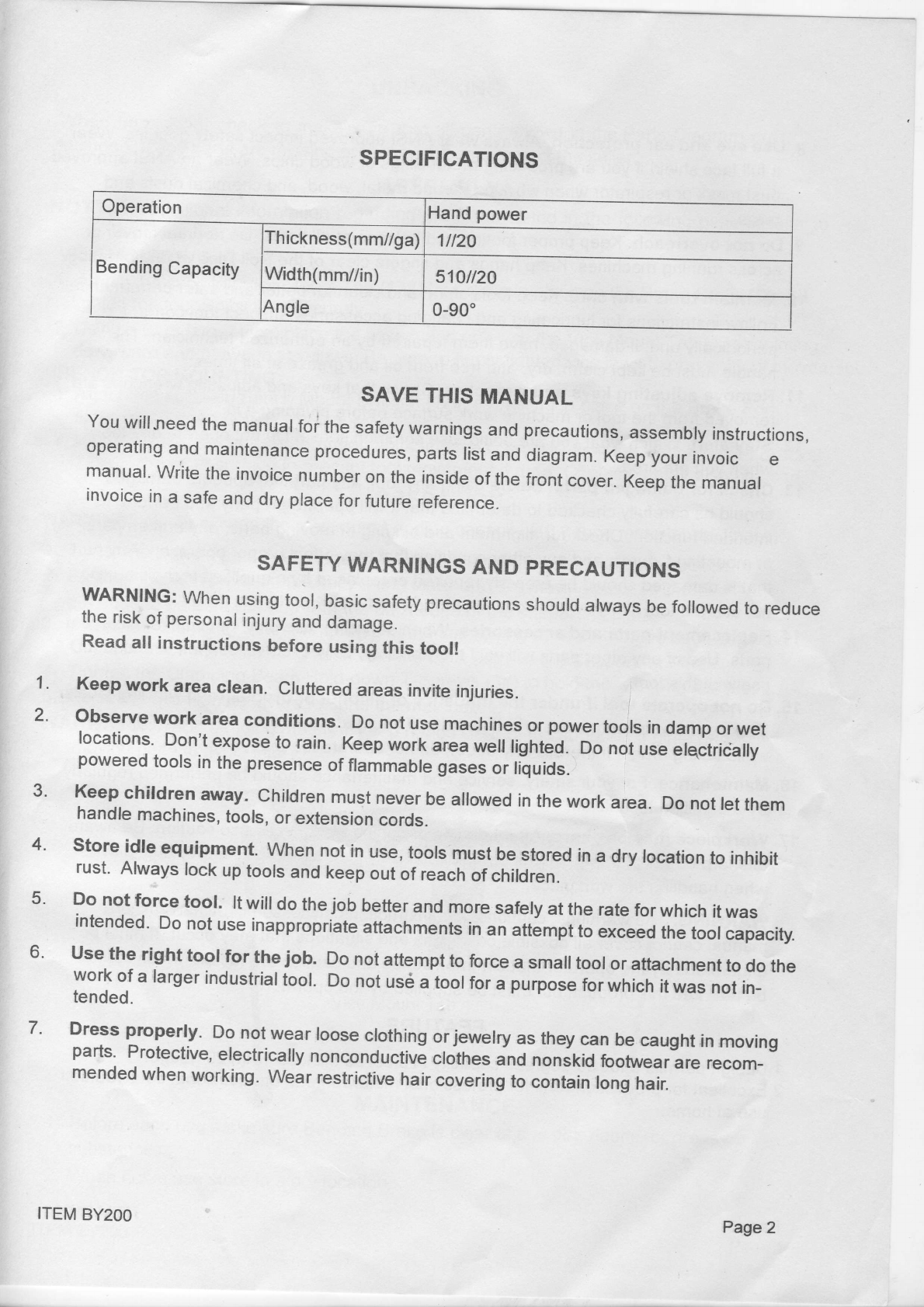
FROST BY200 Quick reference guide

20"FOLDER
lI= BYaOO
tvr
"
ASSEMBLY
&OPERATING
INSTRUCTIONS
Diagramswithinthismanual
maynotbedrawn
proportionally.
Due
tocontinuing
improvements,actual
product
may
differslightly
fromthe
product
described
herein.
Read
thismaterialbeforeusing
thisproduct.
Failure
todosocan
result
in
serious
injury.
SAVE
THISMANUAL.

SPECIFICATIONS
Operation Hand
power
Bending
Capacity Thickness(mm//ga)
1il20
Width(mm//in) 510il20
Angle 0-90'
SAVE
THIS
MANUAL
You
willneed
the
manual
toi
the
safety
warnings
and
precautions,
assembly
instructions,
operating
and
maintenance
procedures,
parts
list
and
diagram.
Keep
your
invoic e
manual'
wiitethe
invoice
number
on
theinside
of
the
front
cover.
Keep
the
manual
invoice
in
asafe
and
dry
place
for
future
reference.
SAFETY
WARNINGS
ANDPRECAUTIONS
WARNING:
When
using
tool,
basic
safety
precautions
should
always
befollowed
toreduce
therisk
of
personal
injury
and
damage.
Read
allinstructions
before
using
this
tool!
Keep
work area
clean. Cluttered
areas
invite
injuries.
observework area
conditions. Do
not
use
machines
orpower
tools
in
damp
or
wet
locations'
Don't
expose
torain. Keep
work
area
wetl
lighted.
Do
not
use
elqctrically
poweredtoo|sinthepresenceoff|ammab|egaseSor|iiuids.
Keep
children
away.Children
must
never
be
allowed
in
the
work
area.Do
not
let
them
handle
machines,
tools,
or
extension
cords.
Storeidle
equipment.When
not
in
use,
tools
must
be
stored
in
adrylocation
toinhibit
rust'Always
lock
up
toors
and
keep
out
ofreach
of
chirdren.
Donotforce
tool. lt
will
do
the
jobbetter
and
more
safety
at
the
rate
for
which
it
was
intended'
Do
not
use
inappropriate
attachments
in
anattempt
to
exceed
the
toolcapacity.
usetherighttoolfor the
job. Do
not
attempt
to
force
asmall
tool
or
attachment
todo
the
work
of
alarger
industrial
tool.
Do
not
us6
atool
for
apurpose
forwhich
it
was
not
in-
tended.
Dress
properly. Do
not
wear
loose
clothing
or
jewelry
as
they
can
becaught
in
moving
parts'Protective,
electrically
nonconductive
cloihes
and
nonskid
footwear
arerecom-
mended
when
working.
Wear
restrictive
hair
covering
tocontain
long
hair.
1.
2.
3.
4.
5.
6.
7.
ITEM
BY2OO Page2

8.U$e
eye
and earprotectipn.
Always
wear
ANSI
approved
impact
safety
goggles.
Wear
afull
face
shield
if
you
are
producing
metal
filings
or
wood
chips.
Wear
an
ANSI
approved
dust
mask
or
respirator
when
working
around
metal,
wood,
and
chemical
dusts
and
mists.
9.
Donotoverreach.
Keep
proper
footing
and
balance
atalltimes.
Do
not
reach
over
or
across
running
machines.
Keep
hands
and
fingers
clear
of
the
Roll
Dies
when
operating.
10'Maintain
toolswith care.
Keep
tools
sharp
and
clean
for
better
and
safer
performance
Follow
instructions
forlubricating
and
changing
accessories.
lnspect
tool
cords
periodically
and,
if
damaged,
have
them
repaired
by
an
authorized
technician.
The
handle
must
be
kept
clean,
dry,
andfree
from
oil
and
grease
at
alltimes.
11'Remove
adjustingkeysandwrenches.
Check
that
keys
and
adjusting
wrenches
are
removed
from
the
tool
ormachine
work
surface
before
plugging
itin.
12'
Qtay
alert.
Watch
wliat
you
are
doing,
use
common
sense.
Donot
operate
any
tool
when
you
are
tired.
13'check for damaged
parts.
Before
using
any
tool,
any
part
that
appears
damaged
should
be
carefully
checked
todetermine
thatit
will
operate
properly
and
perform
its
intended
function.
Check
for
alignment
and
binding
of
moving
parts;
any
broken
parts
ormounting
fixtures;
and
any
other
condition
that
may
affect
proper
operation.
Any
part
that
is
damaged
should
beproperly
repaired
orreplaced
by
aqualified
technician.
Do
not
use
the
tool
if
afiy
switch
does
not
turn
onand
off
properly.
14'
Replacement
parts
andaccessories.
When
servicing,
use
onlyidentical
replacement
parts.
Use
of
any
other
parts
will
void
the
warranty.
Only
use
accessories
intended
for
use
with
this
tool.
15.
Donotoperate
t'ool
if under
theinfluence
of alcoholor drugs.Read
warning
labels
if
taking
prescription
medicine
todetermine
if
your
judgment
orreflexes
areimpaired
while
taking
drugs.
lf
there
is
any
doubt,
do
not
operate
the
tool.
16'Maintenance.
For
your
safety,
service
and
maintenance
should
beplrformed
regularly
by
aqualified
technician.
17'
Workpiece
may
be
sharp.
After
bending
or
cutting
workpieces
use
caution.
Be
aware
of
sharp
edges
orsharp
shreds
ofmetal
that
may
be
created.
Use
heavy
duty
gloves
when
handling
the
workpiece.
WhnrulruC:
The
warnings,
cautions,
and
instructions
discussed
in
this
instruction
manual
cannot
cover
all
possible
conditions
and
situations
that
may
occur.
lt
must
be
understood
by
the
operator
that
common
sense
and
caution
are
factors
which
cannot
be
built
into
this
product,
but
must'be
supplied
by
the
operator.
FEATURE
1'Designpermits
afull
g0
degrees
capacity
in
steel
as
thick
as1mml20gauge.
2'Excellent
for
production
runs
for
professional
metalworkers,
oroccasio'nal
do-it-yourself
use
at
home.
Page
3ITEM
BY2OO

UNPACKING
When
unpacking,
check
tomake
sure
that
all
parts
shown
inthe
parts
Diagram
are
included.
lf
any
parts
are
missing
orbroken,prease
contact
the
seiler.
NOTE:For
additional
information
the
Parts
Diagram.
VICE
MOUNTING
1'
Attach
the
supplied
Vice
Mount
Tab(13#)
by
bolting
in
place
on
the
Brake
Body(1#)
and
tighten
the
four
Botts(11#)
securely.
2'
Using
a6"
orlarger
vice,
place
the
assembled
unit
with
the
Vice
Mount
Tab
(13#)
pointing
downward
and
between
vice
jaws.
Be
sure
to
firmly
tighten
vice
jaws
toprevent
tool
movement.
BENGH.TOP
MOUNTING
1'
Attach
the
supplied
Bench
Mount
Bracket
(12#)
by
bolflng
in
place
on
the
Brake
Body(1#)
gldes
and
tihgten
Bolts(11#)
securety.
2' Using
suitable
lag
bolts'or
throungh
-bolts
and
nuts,
securely
bolt
the
Bench
Mount
Bracket
(12#)
to,the
work
surface
toprevent
tool
movement.
Large
"-C"
clamps
may
also
be
used.
OPERATION
WARNING!
Never
exceed
the
maximum
bending
capacity
(18
gauge
material
thickness).
1' Lower
the
Handle
until
the
Extension
Fence
becomesparallel
to
the
workbench.
2' Position
the
workpiece
on
the
supportingplate
and
the
movingplate
so
that
_ the
edge
to
be
bent
lines
up
with
the
back
edge
ofthe
supporting
plate.
3' Place
the
clamping
Beam(4#)
on
top
of
the
iupporting
plate
so-tnaithe
back
edge
the
clamping
Beam(4#)
lines
up
flush
with
the
back
edge
of
the
supporting
plate.
4' Tighten
the
clamping
Beam
Hold-down
T-screws
(C*)
tohold
the
workpiece
in
place.
5. Raise
the
two
Handre
revers
tobend
the
materiar.
WARNING!
When
bending
materiat,
keep
hands
clear
of
the
supporting
plate
and
movingplate
to
avoid
injury.
gPlate
Bench
Mount
Tab Clamping
Beam Moving
Plate
Vice
Mount
Tab
MAINTENANCE
Before
each
use
make
sure
Bending
Brake
is
ctear
of
any
dirt,
debris,
or
greasy
substances.
When
not
in
use
store
in
adry
location.
ASSEMBLY
regarding
theParts
Listed
inthe
foilowingpage
5,refer
to
1.
2.
ITEM
BY2OO Page
4

PARTS
LIST
PartNo. Description QW
1BrakeBodv 1
2Washer12mm 2
3T-Screw 2
4Clamoinq
Beam 1
5Bolt
M8X25 2
6HandleLever 2
7NutM8 2
8Sorino 2
9ExtensionFence 1
10 Washer8mm 11
11 BoltM8X16 11
12 Bench
MountBracket 2
13 ViceMountTab 1
14 Handle
Ball 2
PARTS
DIAGRAM
L
Page5 ITEMBY2OO
Table of contents
Popular Folding Machine manuals by other brands

Horizon Fitness
Horizon Fitness SPF-20A manual

TOSINGRAF
TOSINGRAF PIEGA TOP OFFICE Instructions for installation and use

Martin Yale
Martin Yale P6400 Maintenance and operating instructions

Galaxy
Galaxy FM500 instruction manual

Morgana
Morgana AutoFold Pro Operator's manual

Formax
Formax FD 6100 Service manual