FrSky RB-20 User manual

Instruction Manual for FrSky RB-20
Specifications:
Recommended input voltage range: DC 4~8.4V (1~2s Lipo or 4~6s NiMH)
Number of servos: up to 15
Operating temperature: -20℃~75℃
Weight: 37g
Dimension: 77×43×22mm
Features:
High voltage servo supported
Overload protection on each channel
Compatible with other FrSky S.Port products
Dual power and dual receiver
Integrated S.Port telemetry feedbacks (voltage, current, capacity, overload indication, etc.)
Settable servo signal output period: 50Hz of servo outputs (20ms period) or equal to the input of SBUS cycle
Add:F-4,Building C, Zhongxiu Technology Park, No.3 Yuanxi Road, Wuxi, 214125, Jiangsu, China Technical Support: [email protected]
Introduction:
Thank you for purchasing FrSky RB-20. It is a high-performance and multi-function unit. In order to fully enjoy the
benefits of this system, please read the instruction manual carefully and set up the device as described below.
Instruction Manual for FrSky RB-20
Working State:
Red LED Green LED State
Off On Normal
On Off Abnormal
Overload Protection:
The RB-20 has overload protection function through a circuit inside on each servo output. If current overload
happens, the affected servo output will be disconnected from the power supply while the remaining servo outputs
are still power on.
The allowed continuous current output on CH1~CH15, S.PORT, RX 1IN, RX 2IN is 5A. When the continuous
current is over 10A, the RB-20 will activate overload protection immediately 23℃.
Temperature Ihold (A) Itrip (A)
23℃5.00 10.00
50℃3.95 7.90
70℃3.35 6.70
Overview:
CH1~CH15 - connect up to 15 servos (PWM)
RX1 S.P - connect to the S.Port of RX1
RX2 S.P - connect to the S.Port of RX2
S.PORT - connect to the S.Port of FrSky products with S.Port
RX1 IN - connect to the SBUS port of the receiver
RX2 IN - connect to the SBUS port of the receiver
BATT 1&BATT 2 - MPX connectors for batteries or BEC connection, supply power for RB-20 and connected
receivers
LED R
LED G
RX2 S.P
RX1 S.P
DC
Caution: Do not connect power supplies to CH1~CH15, S.PORT, RX1 S.P, RX2 S.P, RX1 IN and RX2 IN.
Power Supply:
Power supply of RB-20 could be provided from either one battery/BEC (connect via BATT1 or BATT2), or two
(connect to BATT1 and BATT2). When two power supplies are used, make sure both supply the maximum
continuous current of 40A and the maximum peak current of 120A. Otherwise overload protection could not
function efficiently.
If the voltages of two power supplies are the same, power can be used from both supplies at the same time;
If the voltages of two power supplies are different, the power comes from the one with the higher voltage, and
each supply is isolated from each other instead of shared.
Application of batteries with different capacity, number of cells and chemistry type is allowed.
Please ensure output power on one of the two power supplies is no less than the maximum operation power of
the connected devices (servos, etc.), or insufficient power supply on the connected devices may occur.
The RB-20 is a switchboard connected to power supplies, receivers, servos and S.Port sensors. The RB-20 does
not contain circuitry to stabilize or regulate voltage to the servos. The level of the input voltage is equal to the level
of (output) supplied voltage to the servos. Be sure to match the proper type of servos with your selected power
supply (for example: when using 2 LiPo cells without a regulator, it is necessary to use servos labeled “High
Voltage”).
Do not use Y harness to connect more than one servo to each servo output.
Connection:
1
2
3
4
5
6
7
8
SBUS
8/16CH TELEMETRY
RSSI
PORT
SBUS
1
2
3
4
5
6
7
8
SBUS
8/16CH TELEMETRY
RSSI
PORT
SBUS
LED R
LED G
RX2 S.P
RX1 S.P
DC
FrSky S.Port Sensors
Note
R-XSR,G-RX8 and RX8R PRO could enable/disable telemetry through S.Port.
X8R,X4R and XSR could enable/disable telemetry through S.Port with the firmware above and
V180125.
What's New!
Multi-channel output
Higher operating current (The current is twice as big as RB) and supporting high-current servos
(Please refer to the chart in Overload Protection)
Automatically selected telemetry between RX1 and RX2:
decide on/off of telemetry on RX1 and RX2 through RX1 S.P and RX2 S.P

Add:F-4,Building C, Zhongxiu Technology Park, No.3 Yuanxi Road, Wuxi, 214125, Jiangsu, China Technical Support: [email protected]
FrSky is continuously adding features and improvements to our products. To get the most from your product, please check
the download section of the FrSky website www.frsky-rc.com for the latest update firmware and manuals.
Add:F-4,Building C, Zhongxiu Technology Park, No.3 Yuanxi Road, Wuxi, 214125, Jiangsu, China Technical Support: 
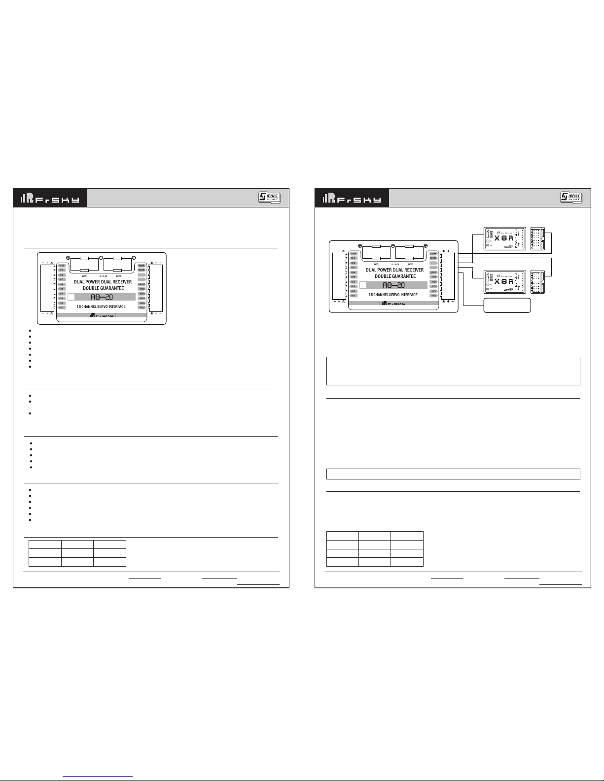
[email protected]
How to change the SBUS signal from negative to positive for RX1 IN and RX2 IN:
The SBUS signal from FrSky Redundancy Bus is negative. Follow the steps below to change it from negative to
positive.
Take RX1 IN for example
I. Connect the signal pins of CH11 and CH12 by a jumper
II. Connect the power supply to BATT1 or BATT2 and the GREEN LED will Flash
III. Remover the jumper and disconnect the power supply
Note
Connect the signal pins of CH13 and CH14 by a jumper, and follow I & II to change the SBUS signal
from negative to positive for RX2 IN.
Connect the signal pins of CH11 and CH12, CH13 and CH14 by jumpers, and follow I & II to change
the SBUS signal from negative to positive for RX1 IN and RX2 IN at the same time.
Follow step I & III to switch back the SBUS signal from positive to negative.
Setting for Servo Signal Output Period:
The default period of the signal output is 20ms, and it could be set to the receiver synchronized.
Analog servos are not recommended to set to receiver synchronized.
Follow the steps below to set the signal output period:
I. Connect the signal pins of CH1 and CH2 by a jumper
II. Connect the power supply to BATT 1 or BATT 2
III. The GREEN LED flashes quickly, indicating that signal output period has been synchronized with that of the
receiver (from 20ms to the desired value)
IV. Disconnect both the jumper from CH1 and CH2 and the power supply
How to distinguish between 20ms and the receiver synchronized
Connect a receiver to RX1 IN or RX2 IN, then connect power supply to BATT1 or BATT2. If GREEN LED flashes
quickly, it is receiver synchronized output. If stay on, it is 20ms output.
How to update the firmware
Update the RB-20 through S.PORT interface
Instruction Manual for FrSky RB-20 Instruction Manual for FrSky RB-20
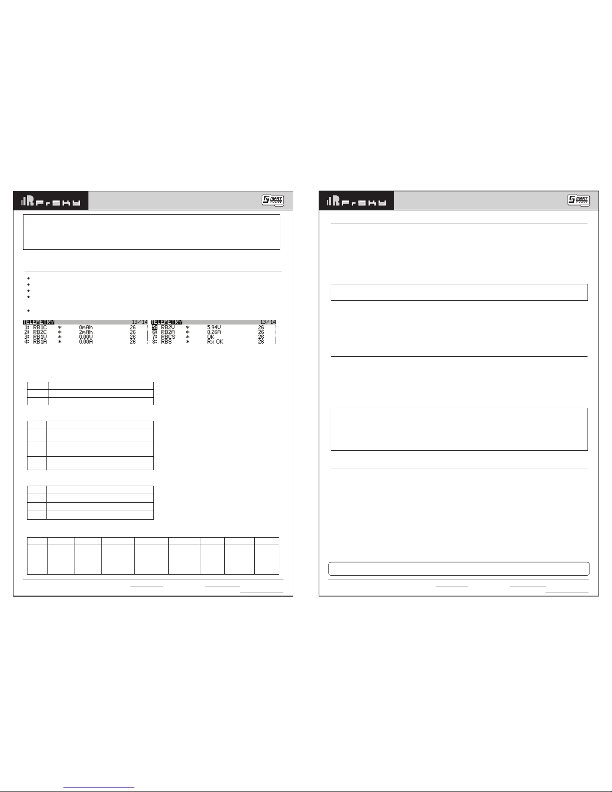
Values:
Voltage — actual voltages of both inputs
Current — actual current flowing from the power supply to the output
Capacity — consumed capacity of each power supply
Over-I Monitor — indication of servo status( good or overloaded); indication of receiver status;numbers of
detected channels and output period of signal
All values above will be transmitted to FrSky radio system in real time
Note
I hold means the maximum current passes through the device without tripping under the above three
conditions.
I trip means the minumum current passing through the device will cause trip under the above three
conditions.
Attention
1. Only failsafe set on the receiver which is connected to RX1 S.P will work.
2. RB-20 doesn't support hotplug. When RX1 or RX2 is replaced halfway, RB-20 needs to be repowered on.
3. Make sure both of the receivers output the same signal. For example,when S8R and X8R are used
together, disable gyro on S8R, or they will output different signals.
4. Two receivers could be bound to the same RF module. Also, users could bind RX1(RX2) to IXJT and
RX2(RX1) to the external module XJT, but the S.Port of the external module should be disabled (The
transmitter could only get the S.Port signal from one module by now).
5. RB-20 will manage the telemetry of the two receivers automatically after connecting the devices.
There’s no need to disable the telemetry while binding RX1/RX2.
Note: If you want to change back to the default servo signal output period(20ms), please follow STEP
Ⅰ&Ⅱabove without connecting any receiver.
RBnC: total power usage of battery n
RBnV: the voltage of battery n
RBnA: the current of battery n
RBCS:
1.
2. When using SD logs function, if the RBCS has a non-zero value, such as 64, Convert 64 to binary 100000,
As you can see from the table, the channel 7 overloader or Voltage less than 4V.
RBS:
1.
2. When using SD logs function, if the RBS has a non-zero value, such as 6, Convert 6 to binary 00110,As you
can see from the table,the RX1 lostFrame & Rx2 failsafe.(0 is normal)
Display Definition for Value
OK normal
CHnH CHn overload or undervoltage (Less than 4 v).
Display
RX OK
RXn_FS
RXn_LF
Definition for Value
Normal
Rxn failsafe
Rxn lost Frame
BitX
Bit n
(n≤15)
Bit 16
Bit 17
Definition for Value
0: channel n+1 normal
1: channel n+1 overloader or Voltage less than 4V
0: RX1 normal
1: RX1 overloader or Voltage less than 4V
0: RX2 normal
1: RX2 overloader or Voltage less than 4V
Bit X
Definition
for Value
Bit 0
1: RX1_
FAIL SAFE
Bit 1
1: RX1_
FRAME_LOST
Bit 2
1: RX2_
FAIL SAFE
Bit 3
1: RX2_
FRAME_LOST
Bit 4
1: RX1_
PHYSICAL_
CONNECTION_
LOST
Bit 5
1: RX2_
PHYSICAL_
CONNECTION_
LOST
Bit 6
1: RX1_
NO_SIGNAL
Bit 7
1: RX2_
NO_SIGNAL
Popular Switch manuals by other brands

SPX FLOW
SPX FLOW Ultima Switch instruction manual

Smart Technologies
Smart Technologies SMART Hub VE220 Administrator's guide

Tripp Lite
Tripp Lite 932845 owner's manual

Tripp Lite
Tripp Lite NGI-M08POE8-L2 owner's manual

Celabs
Celabs SW204HD instruction manual

Qlogic
Qlogic InfiniBand 12200-BS01 quick start guide

Metropolitan Industries
Metropolitan Industries ion Technologies Ion+ Connect Operation manual

3One data
3One data IPS7112G-4GS-8GPOE user manual

CoolGear
CoolGear USBG-4U2ML installation guide

Tripp Lite
Tripp Lite 0SU22081 Brochure & specs

SMART-AVI
SMART-AVI HKM-02 installation manual

3One data
3One data ICS5428 Series Quick installation guide