NOTICE
IF, DURING THE WARRANTY PERIOD, THE CUSTOMER USES A PART FOR THIS MANITOWOC FOOD SERVICE
EQUIPMENT OTHER THAN AN UNMODIFIED NEW OR RECYCLED PART PURCHASED DIRECTLY FROM FRYMASTER
OR ANY OF ITS AUTHORIZED SERVICERS, AND/OR THE PART BEING USED IS MODIFIED FROM ITS ORIGINAL
CONFIGURATION, THIS WARRANTY WILL BE VOID. FURTHER, FRYMASTER AND ITS AFFILIATES WILL NOT BE
LIABLE FOR ANY CLAIMS, DAMAGES OR EXPENSES INCURRED BY THE CUSTOMER WHICH ARISE DIRECTLY OR
INDIRECTLY, IN WHOLE OR IN PART, DUE TO THE INSTALLATION OF ANY MODIFIED PART AND/OR PART
RECEIVED FROM AN UNAUTHORIZED SERVICER.
NOTICE
This appliance is intended for professional use only and is to be operated by qualified personnel only. A Frymaster
Factory Authorized Servicer (FAS) or other qualified professional should perform installation, maintenance, and
repairs. Installation, maintenance, or repairs by unqualified personnel may void the manufacturer’s warranty. See
Chapter 1 of this manual for definitions of qualified personnel.
NOTICE
This equipment must be installed in accordance with the appropriate national and local codes of the country and/or
region in which the appliance is installed. See NATIONAL CODE REQUIREMENTS in Chapter 2 of this manual for
specifics.
NOTICE TO U.S. CUSTOMERS
This equipment is to be installed in compliance with the basic plumbing code of the Building Officials and Code
Administrators International, Inc. (BOCA) and the Food Service Sanitation Manual of the U.S. Food and Drug
Administration.
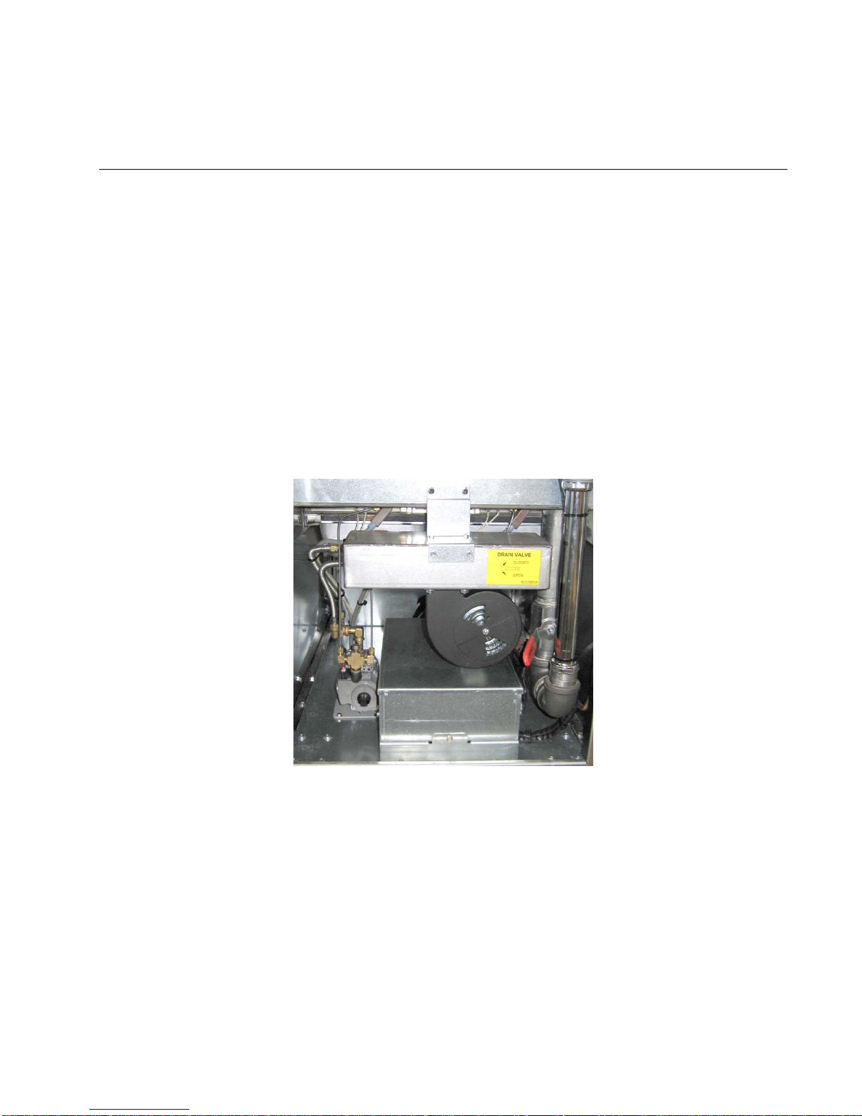
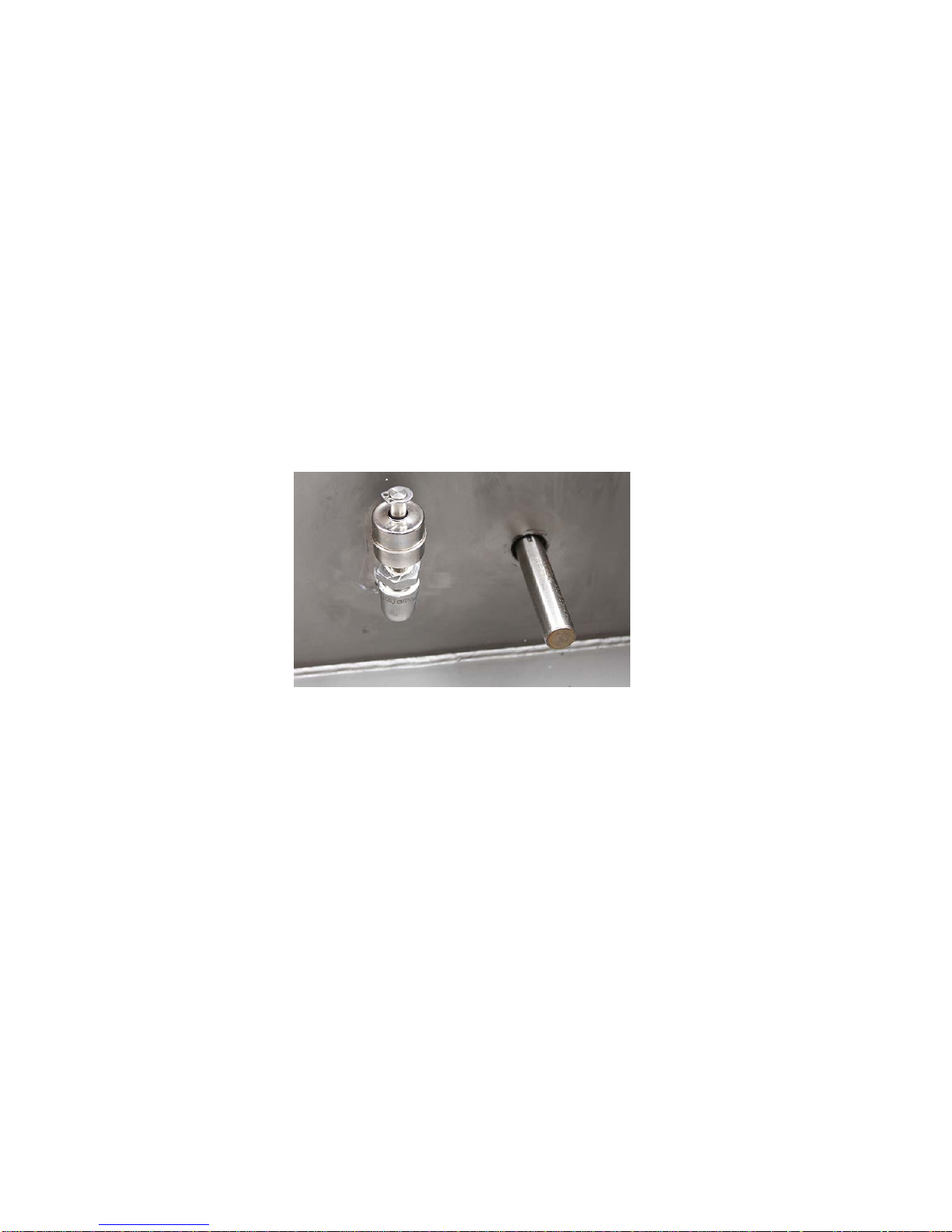
NOTICE
Drawings and photos used in this manual are intended to illustrate operational, cleaning and technical procedures
and may not conform to onsite management operational procedures.
NOTICE
This appliance is intended to be used for commercial applications, for example in kitchens of restaurants, canteens,
hospitals and in commercial enterprises such as bakeries, butcheries, etc., but not for continuous mass production
of food.
DANGER
Improper installation, adjustment, maintenance or service, and unauthorized alterations or modifications can cause
property damage, injury, or death. Read the installation, operating, and service instructions thoroughly before
installing or servicing this equipment. Only qualified service personnel may convert this appliance to use a gas other
than that for which it was originally configured.
DANGER
No structural material on the cooker should be altered or removed to accommodate placement of the cooker under a
hood. Questions? Call the Frymaster Service Hotline at 1-800-551-8633.
WARNING
After installation of a gas cooker and after any maintenance to the gas system of a gas cooker-manifold, valve,
burners, etc. – check for gas leaks at all connections. Apply a thick soapy solution to all connections and ensure
there are no bubbles. There should be no smell of gas.
NOTICE
The Commonwealth of Massachusetts requires any and all gas products to be installed by a licensed plumber or pipe
fitter.
DANGER
Adequate means must be provided to limit the movement of this appliance without depending upon the gas line
connection. Single cookers equipped with legs must be stabilized by installing anchor straps. All cookers equipped
with casters must be stabilized by installing restraining chains. If a flexible gas line is used, an additional restraining
cable must be connected at all times when the cooker is in use.
CAUTION
No warranty is provided for any Frymaster cooker used in a mobile or marine installation or concession. Warranty
protection is only offered for cookers installed in accordance with the procedures described in this manual. Mobile,
marine or concession conditions of this cooker should be avoided to ensure optimum performance.