Fueltec CF4.0-SPO-UL-PCB User manual

OPERATION MANUAL
FUELTEC MODEL CF4.0-SPO-UL-PCB
SERIAL NUMBER ________
FUELTEC SYSTEMS, LLC
3821 N. MAIN STREET
GRANITE FALLS, NC 28630
(800) 511-4918
©LENZ 2018

General Safety Regulaons
WARNING: Read and understand all instrucons. Failure to follow all instruc-
ons listed below may result in explosion, re ,serious injury, and/or death.
WARNING: The warnings, cauons, and instrucons discussed in this
instrucon manual cannot cover all possible condions or situaons that
could occur. It must be understood by the operator that common sense and
cauon are factors which cannot be built into this product, but must be
supplied by the operator.
INTENDED USE
The System is designed to be used with diesel fuel for removing water and
other contaminants from fuel tanks. The system is designed to draw uid from
the boom of a fuel tank, through a bag lter, water separator and nal lter,
then return the fuel to the tank under minimum back pressure condions.
SAFETY EQUIPMENT
Keep one or more Fire Exnguishers U.L. rated 10A-80B:C in the work area.
Ground chassis to low impedance ground!
CF4.0-UL-PCB OPERATION

CF4.0-UL-PCB OPERATION
WORK AREA
• Keep work area clean, free of cluer and well lit. Cluered and dark work areas
can cause accidents.
• Keep children and bystanders away while installing or operang this system. Dis-
tracons can cause you to lose control, so visitors should remain at a safe distance
from the work area.
• Be aware of all power lines, electrical circuits, water pipes and other mechanical
hazards in your work area, parcularly those hazards below the work surface hid-
den from the operator’s view that may be unintenonally contacted and may
cause personal harm or property damage.
Be alert of your surroundings. Using your system in conned work areas may put
you dangerously close to unsafe condions.
PERSONAL SAFETY
Stay alert, watch what you are doing and use common sense when operang or
maintaining the system. Do not install or maintain the system while you are red
or under the inuence of drugs, alcohol or medicaon. A moment of inaenon
while installing or maintaining the system may result in serious personal injury or
death.
Dress properly while operang this system. Do not expose bare skin or eyes to
fuels. Prolonged contact with fuel can damage the skin.
Use safety apparel and equipment. Use safety goggles or safety glasses with side
shields which comply with current naonal standards, or when needed, a face
shield. This applies to all persons in the work area. Also use non-skid safety shoes,
hardhat, gloves, and hearing protecon when appropriate.


1) SUPPLY VALVE
2) PRIMING PORT
3) PRIMARY FILTER / WATER SEPARATOR
4) WATER DRAIN
5) WATER PROBE
6) LEAK DETECTOR FLOAT
7) FINAL FILTER
8) CHECK VALVE
9) PSI GAUGE
10) FLOW SWITCH
11) CIRCUIT BREAKER/ ON/OFF SWITCH
12) RESET BUTTON
13) JOG PUMP BUTTON
14) MACHINE STATUS LED’s
15) VACUUM SWICTH
8
1
2
3
4
5
6
7
9
10
11 12 13
14
15

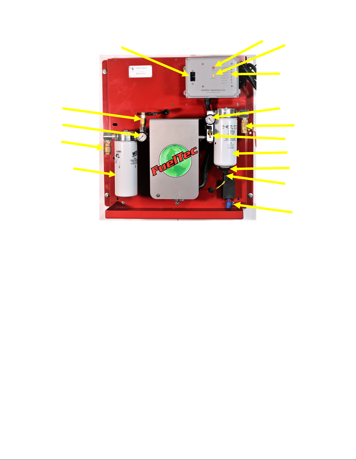
INSTALLING A FUELTEC MODEL CF4.0 SYSTEM
WARNING: Read and understand all instrucons. Failure to follow all instrucons listed be-
low may result in explosion, re ,serious injury, and/or death.
1. Select a locaon close to the fuel storage tank that you will be servicing.
2. Mount the system on a wall, mounng post, or use a Fueltec “tank mounng kit”
3. Install the fuel supply sucon tube in the fuel storage tank access port so that the
sucon tube nozzle is within 1/8 inch of the tank boom. This will insure that even small
droplets of water are removed from the tank.
4. Install an an-siphon valve above the uid level on above ground fuel storage tanks.
5. Provide for thermal expansion on all system piping.
6. Install the clean fuel return to tank piping to a second tank access port, or use a Fueltec
tank ange kit with a telescopic uid pickup tube and return tee, all in one access port.
7. Use one (1”) inch black iron pipe for supply and return piping if the polishing system is
within 30 feet of the above ground fuel storage tank. If run is longer than 30 feet, size
piping adequately for fuel ow.
8. Large underground fuel storage tanks may require a submersible piston pump. To avoid
cavaon and emulsicaon, gear, vane, and turbine pumps are not to be used.
9. A standard household 20 amp fused electric circuit is required.
10. The fuel storage tank and fuel polishing system shall be grounded with a low impedance
ground.
11.Test all piping for leaks aer installaon.
12. CAUTION: PRIME THE PUMP AND SYSTEM BEFORE OPERATING.

NOTE: For best results prime all supply lines and spin-on lters with an external
pump. The following priming instrucons are to be considered an alternave.
Aach 1/4” hose to the hose barb on the priming valve as shown above. Then
open valve.
Priming The CF4.0 Pump

Priming The CF4.0 Pump
Fill a 5 gallon container about 1/2 to 3/4 full with diesel, and insert other end of hose near
the boom of the can.
Priming valve, and the supply valve should be open. Press the jog pump buon. Pump will
start. Run pump for 30 seconds. Repeat this process several mes unl you see the level
going down in the container to wet the pump.
Open the supply valve from the fuel storage tank and run the pump for 30 seconds. Repeat
in 30 second intervals unl the system is primed and you no longer hear the pump
cavitaon. Once the system is primed the no uid ow LED will go out with only the supply
valve open.

The CF4.0 CONTROL PANEL
Basic Operaon:
On power up, unit will go to standby mode, indicated by green LED ashing at slow rate.
To start run cycle, press and release reset buon. (Note: Reset buon should be pressed for approximately one sec-
ond unl green LED ashes at fast rate, then released.) During run cycle, green LED will be lit connuously. Yellow
LED will be lit when pump is energized (6 hours on, 18 hours o).
When a fault occurs, pump is de-energized, green and yellow LEDs are o and the red LED corresponding to the fault
will ash. To reset unit, press and release reset buon. Reset can also be performed by turning o power to unit.
Note: Flow switch faults are ignored during the rst ten seconds of each cycle aer the pump starts.
To reset unit during run cycle (pump may be on or o), press and release reset buon. Unit will go to standby mode
with green LED ashing at slow rate. Press and release reset buon again and unit will start at beginning of cycle.
To operate pump manually press Jog Pump buon. Pump may be operated manually during normal run mode,
standby mode or fault mode.

SYSTEM ALARMS & LEDS
CHANGE PRIMARY SPIN-ON FILTER
CHANGE WATER SEPARATOR COALESCER
CHECK FOR LEAKS
DRAIN SEPARATED WATER
PRIME THE PUMP
PUMP IS RUNNING
SYSTEM IS POWERED UP

CF4.0 DRAIN SEPARATED WATER
To drain water trap:.
Place an approved container at, or under drain valve.
Open drain valve , once all water has been evacuated, close the drain valve.
TURN CLOCKWISE 1/8
TO 1/4 TURN TO OPEN
TURN COUNTER-CLOCKWISE
TO CLOSE

1. Turn System O
2. Close Supply valve
3. Remove plug from probe
4. Remove the spin on lter
5. Remove probe from old lter, reinstall in new lter.
6. Fill new lter with fresh diesel fuel and install.
4. Open supply valve
5. Restart system
6. Check for any leaks.
Primary Spin-on Filter Change

1) Turn o system.
2) Close the Supply valve.
3) Remove old lter.
4) Install new lter.
Final Filter Replacement
This manual suits for next models
1
Table of contents
Other Fueltec Industrial Equipment manuals