Fuji Electric FRENIC-ECO User manual

Instruction Manual
Designed for Fan and Pump Applications
Thank you for purchasing our FRENIC-Eco series of inverters.
• This product is designed to drive a three-phase induction motor. Read through this instruction manual and
be familiar with the handling procedure for correct use.
• Improper handling might result in incorrect operation, a short life, or even a failure of this product as well as
the motor.
• Deliver this manual to the end user of this product. Keep this manual in a safe place until this product is
discarded.
• For how to use an optional device, refer to the installation and instruction manuals for that optional device.
Fuji Electric FA Components & Systems Co., Ltd.
Fuji Electric Corp. of America INR-SI47-1225-E

Copyright © 2007 Fuji Electric FA Components & Systems Co., Ltd.
All rights reserved.
No part of this publication may be reproduced or copied without prior written permission from Fuji Electric FA
Components & Systems Co., Ltd.
All products and company names mentioned in this manual are trademarks or registered trademarks of their
respective holders.
The information contained herein is subject to change without prior notice for improvement.

i
Preface
Thank you for purchasing our FRENIC-Eco series of inverters.
This product is designed to drive a three-phase induction motor for fan and pump applications. Read through this
instruction manual and be familiar with proper handling and operation of this product.
Improper handling might result in incorrect operation, a short life, or even a failure of this product as well as the
motor.
Have this manual delivered to the end user of this product. Keep this manual in a safe place until this product is
discarded.
Listed below are the other materials related to the use of the FRENIC-Eco. Read them in conjunction with this
manual as necessary.
• FRENIC-Eco User's Manual
• RS-485 Communication User's Manual
• Catalog
• Relay Output Card "OPC-F1-RY" Instruction Manual
• Mounting Adapter for External Cooling "PB-F1" Installation Manual
• Panel-mount Adapter "MA-F1" Installation Manual
• FRENIC Loader Instruction Manual
The materials are subject to change without notice. Be sure to obtain the latest editions for use.
Safety precautions
Read this manual thoroughly before proceeding with installation, connections (wiring), operation, or maintenance
and inspection. Ensure you have sound knowledge of the device and familiarize yourself with all safety
information and precautions before proceeding to operate the inverter.
Safety precautions are classified into the following two categories in this manual.
Failure to heed the information indicated by this symbol may lead to
dangerous conditions, possibly resulting in death or serious bodily injuries.
Failure to heed the information indicated by this symbol may lead to
dangerous conditions, possibly resulting in minor or light bodily injuries
and/or substantial property damage.
Failure to heed the information contained under the CAUTION title can also result in serious consequences.
These safety precautions are of utmost importance and must be observed at all times.

ii
Application
• FRENIC-Eco is designed to drive a three-phase induction motor. Do not use it for single-phase motors
or for other purposes.
Fire or an accident could occur.
• FRENIC-Eco may not be used for a life-support system or other purposes directly related to the human
safety.
• Though FRENIC-Eco is manufactured under strict quality control, install safety devices for applications
where serious accidents or material losses are foreseen in relation to the failure of it.
An accident could occur.
Installation
• Install the inverter on a nonflammable material such as metal.
Otherwise fire could occur.
• Do not place flammable matter nearby.
Doing so could cause fire.
• Do not support the inverter by its terminal block cover during transportation.
Doing so could cause a drop of the inverter and injuries.
• Prevent lint, paper fibers, sawdust, dust, metallic chips, or other foreign materials from getting into the
inverter or from accumulating on the heat sink.
Otherwise, a fire or an accident might result.
• Do not install or operate an inverter that is damaged or lacking parts.
Doing so could cause fire, an accident or injuries.
• Do not get on a shipping box.
• Do not stack shipping boxes higher than the indicated information printed on those boxes.
Doing so could cause injuries.

iii
Wiring
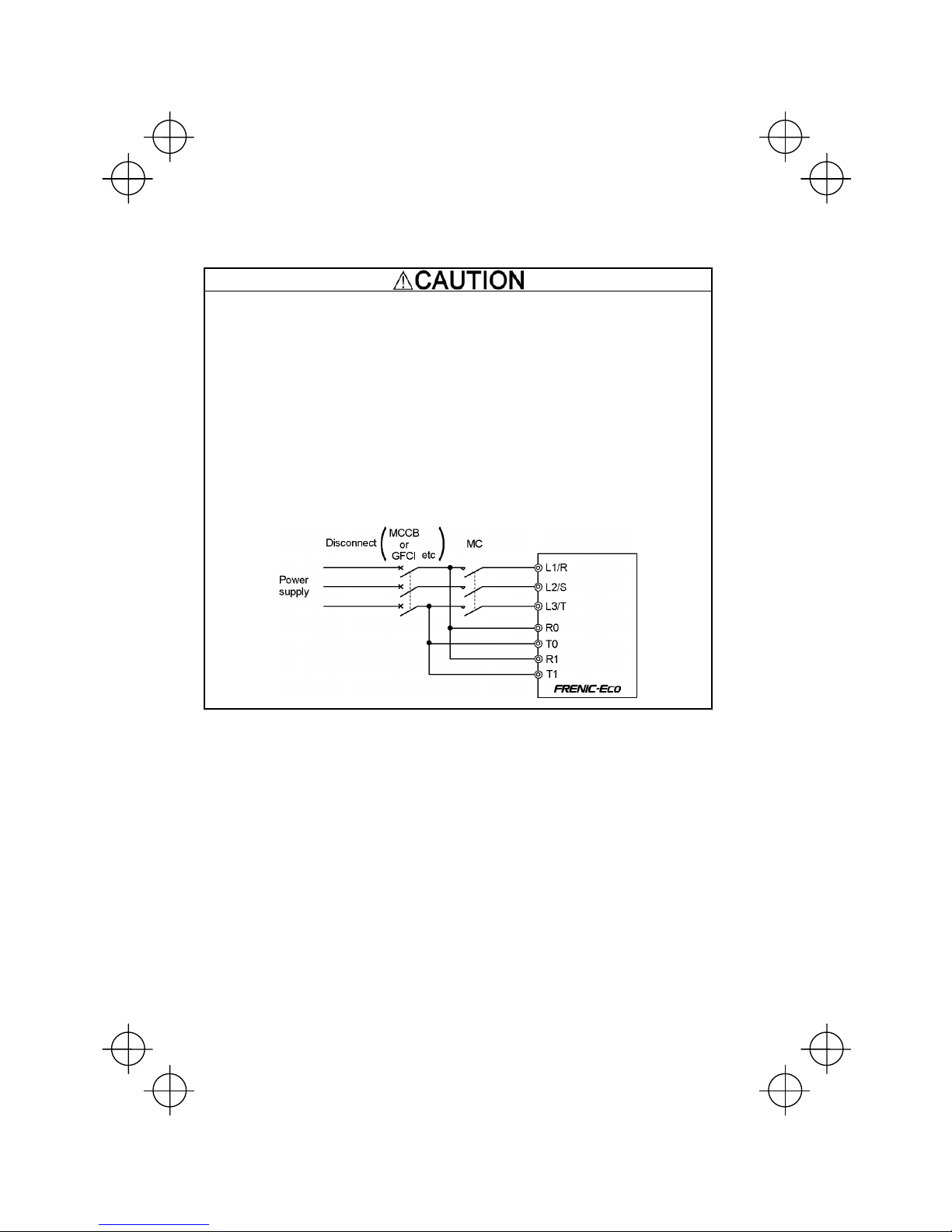
• When wiring the inverter to the power source, insert a recommended molded case circuit breaker
(MCCB) or residual-current-operated protective device (RCD)/a ground fault circuit
interrupter(GFCI)(with overcurrent protection) in the path of power lines. Use the devices within the
recommended current range.
• Use wires in the specified size.
Otherwise, fire could occur.
• Do not use one multicore cable in order to connect several inverters with motors.
• Do not connect a surge suppressor to the inverter's output (secondary) circuit.
Doing so could cause fire.
• Ground the inverter in compliance with the national or local electric code.
Otherwise, electric shock could occur.
• Qualified electricians should carry out wiring.
• Be sure to perform wiring after turning the power OFF.
Otherwise, electric shock could occur.
• Be sure to perform wiring after installing the inverter body.
Otherwise, electric shock or injuries could occur.
• Ensure that the number of input phases and the rated voltage of the product match the number of
phases and the voltage of the AC power supply to which the product is to be connected.
Otherwise fire or an accident could occur.
• Do not connect the power source wires to output terminals (U, V, and W).
Doing so could cause fire or an accident.
• Generally, control signal wires are not enforced- insulated. If they accidentally touch any of live parts in
the main circuit, their insulation coat may break for any reasons. In such a case, an extremely high
voltage may be applied to the signal lines. Make a complete remedy to protect the signal line from
contacting any hot high voltage lines.
Otherwise, an accident or electric shock could occur.
• Wire the three-phase motor to terminals U, V, and W of the inverter, aligning phases each other.
Otherwise injuries could occur.
• The inverter, motor and wiring generate electric noise. Take care of malfunction of the nearby sensors
and devices. To prevent the motor from malfunctioning, implement noise control measures.
Otherwise an accident could occur.

iv
Operation
• Be sure to install the terminal block cover and the front cover before turning the power ON. Do not
remove the covers while power is applied.
Otherwise electric shock could occur.
• Do not operate switches with wet hands.
Doing so could cause electric shock.
• If the retry function has been selected, the inverter may automatically restart and drive the motor
depending on the cause of tripping.
(Design the machinery or equipment so that human safety is ensured after restarting.)
• If the stall prevention function (current limiter), automatic deceleration, and overload prevention control
have been selected, the inverter may operate at an acceleration/deceleration time or frequency
different from the commanded ones. Design the machine so that safety is ensured even in such cases.
Otherwise an accident could occur.
• The key on the keypad is effective only when the keypad operation is enabled with function code
F02 (= 0, 2 or 3). When the keypad operation is disabled, prepare an emergency stop switch separately
for safe operations.
Switching the run command source from keypad (local) to external equipment (remote) by turning ON
the "Enable communications link" command (LE) or "Switch run command 2/1" command (FR2/FR1),
disables the key. To enable the key for an emergency stop, select the STOP key priority with
function code H96 (= 1 or 3).
• If an alarm reset is made with the Run command signal turned ON, a sudden start will occur. Ensure that
the Run command signal is turned OFF in advance.
Otherwise an accident could occur.
• If you enable the "Restart mode after momentary power failure" (Function code F14 = 3, 4, or 5), then
the inverter automatically restarts running the motor when the power is recovered.
(Design the machinery or equipment so that human safety is ensured after restarting.)
• If you set the function codes wrongly or without completely understanding this instruction manual and
the FRENIC-Eco User's Manual, the motor may rotate with a torque or at a speed not permitted for the
machine.
An accident or injuries could occur.
• Do not touch the inverter terminals while the power is applied to the inverter even if the inverter stops.
Doing so could cause electric shock.

v
• Do not turn the main circuit power (circuit breaker) ON or OFF in order to start or stop inverter operation.
Doing so could cause failure.
• Do not touch the heat sink because they become very hot.
Doing so could cause burns.
• Setting the inverter to high speeds is easy. Before changing the frequency (speed) setting, check the
specifications of the motor and machinery.
• The brake function of the inverter does not provide mechanical holding means.
Injuries could occur.
Setting control switches
• Before setting up any internal control switches, turn OFF the power and wait more than five minutes for
models of 30HP for 208V, 40HP for 460V or below, or ten minutes for models of 40HP for 208V, 50HP
for 460V or above. Make sure that the LED monitor and charging lamp (on models of 40HP for 208V,
50HP for 460V or above) are turned OFF. Further, make sure, using a multimeter or a similar
instrument, that the DC link bus voltage between the terminals P (+) and N (-) has dropped below the
safe voltage (+25 VDC).
Otherwise electric shock could occur.
Maintenance and inspection, and parts replacement
• Turn the power OFF and wait for at least five minutes for models of 30HP for 208V, 40HP for 460V or
below, or ten minutes for models of 40HP for 208V, 50HP for 460V or above, before starting inspection.
Further, check that the LED monitor and charging lamp (on models of 40HP for 208V, 50HP for 460V or
above) are unlit and that the DC link bus voltage between the P (+) and N (-) terminals is lower than 25
VDC.
Otherwise, electric shock could occur.
• Maintenance, inspection, and parts replacement should be made only by qualified persons.
• Take off the watch, rings and other metallic objects before starting work.
• Use insulated tools.
Otherwise, electric shock or injuries could occur.
Disposal
• Treat the inverter as an industrial waste when disposing of it.
Otherwise injuries could occur.
Others
• Never attempt to modify the inverter.
Doing so could cause electric shock or injuries.
GENERAL PRECAUTIONS
Drawings in this manual may be illustrated without covers or safety shields for explanation of detail parts.
Restore the covers and shields in the original state and observe the description in the manual before
starting operation.

vi
Conformity with Low Voltage Directive in the EU
If installed according to the guidelines given below, inverters marked with CE can be considered to be compliant
with the Low Voltage Directive 73/23/EEC.
1. Be sure to earth the grounding terminal zG. Use an earth wire sized more than that of the power wires
used in the power dispatch system. Do not use a residual-current-operated protective device (RCD)* or a
ground fault circuit interrupter(GFCI)* as a sole mechanism of electric shock protection.
*With overcurrent protection.
2. Use an MCCB, RCD/GFCI or MC in conformity with EN or IEC standards.
3. When an RCD/GFCI is used for protection of electric shock caused by a direct or indirect contact to the
live parts, insert a type B RCD/GFCI in input lines (primary) of the inverter for the 3-phase 208 V or 460 V
power source.
4. Use inverters in an environment that does not exceed pollution degree 2. If inverters are to be used in an
environment with pollution degree 3 or 4, place them in an enclosure of IP54 or above.
5. To protect human body from an electric shock caused by a contact to live parts, install inverters, AC
reactor and input /output filter in the enclosure of IP2X. In the case where human body easily contacts to
live parts, a top panel of the enclosure should be IP4X or higher.
6. Do not directly connect a copper wire to the grounding terminal. Use a crimp terminal with tin or equivalent
plating to connect the earth wire.
7. When using inverters at an altitude of more than 6600ft(2000 m), note that the basic insulation applies to
the insulation degree of the control circuitry. At an altitude of more than 9800ft(3000 m), inverters cannot
be used.

vii
Conformity with Low Voltage Directive in the EU (continued)
8. Use the wires listed in EN60204-1.
*1The frame size and model of the MCCB or RCD/GFCI (with overcurrent protection) will vary, depending on the
power transformer capacity. Refer to the related technical documentation for details.
*2The recommended wire size for main circuits is for the 70°C(158°F) 600V PVC wires used at an ambient
temperature of 40°C(104°F).
Recommended wire size (mm2)
Control circuit
MCCB or
RCD/GFCI *1
Rated current
(A)
Main power
input *2
[L1/R, L2/S, L3/T]
Inverter’s
grounding [zG]
Power supply voltage
Nominal applied
motor (HP)
Inverter type
W/
DCR
W/o
DCR
W/
DCR
W/o
DCR
Inverter outputs *2
[U, V, W]
DC reactor
[P1, P(+)]
Europe type
terminal block
Aux. control power
supply [R0, T0]
Aux. fan power
supply [R1, T1]
1 FRN001F1S-2U 15
2 FRN002F1S-2U
3 FRN003F1S-2U
10 20 2.5
5 FRN005F1S-2U 20 30
2.5
4.0
2.5 2.5
7 FRN007F1S-2U 40 75 6.0 10 6.0
6.0
10 FRN010F1S-2U 50 100 10 16 10 16
15 FRN015F1S-2U 75 125 16 25 16 25
20 FRN020F1S-2U 150 25 35 25
25 FRN025F1S-2U
100 175 35 50
35 35
30 FRN030F1S-2U 150 200 50 70 50 70
40 FRN040F1S-2U 175 250 16x2 35x2 25x2 25x2
-
50 FRN050F1S-2U 200 300 50x2 95 95
60 FRN060F1S-2U 250 350 95 70x2 50x2
75 FRN075F1S-2U 50x2 70x2 50x2
100 FRN100F1S-2U 350 95x2 95x2 95x2
Three-phase 208 V
125 FRN125F1S-2U 500
-
240
-
240 120x2
0.25
to
0.75
2.5
2.5
1 FRN001F1S-4U 5
2 FRN002F1S-4U
5 10
3 FRN003F1S-4U 15
5 FRN005F1S-4U
10 20
7 FRN007F1S-4U 15 30
2.5
10 FRN010F1S-4U 20 40
2.5
4.0
2.5 2.5
15 FRN015F1S-4U 30 50 4.0 6.0 4.0 4.0
20 FRN020F1S-4U 60 10 6.0 6.0
25 FRN025F1S-4U 40 75 6.0 10
30 FRN030F1S-4U 50 100 10 16 10
16
40 FRN040F1S-4U 75 16 25 16
50 FRN050F1S-4U 125 35 25
60 FRN060F1S-4U
100 150 25 50 35 35
-
75 FRN075F1S-4U 125 200 35 25x2 16x2 50
100 FRN100F1S-4U 175 70 25x2 25x2
125 FRN125F1S-4U 200 95 95
150 FRN150F1S-4U 250 50x2 50x2 120
200 FRN200F1S-4U 300 70x2 70x2 70x2
250 FRN250F1S-4U 150 185 240
300 FRN300F1S-4U 185 240 120x2
350 FRN350F1S-4U
500
240
400 FRN400F1S-4U 150x2 150x2 150x2
450 FRN450F1S-4U 600 185x2 185x2
500 FRN500F1S-4U 800 185x2 240x2 240x2
600 FRN600F1S-4U 240x2 185x3
700 FRN700F1S-4U 1000 185x3 240x3 240x3
800 FRN800F1S-4U 240x3 185x4
Three-phase 460 V
900 FRN900F1S-4U 1200
-
185x4
-
240x4 240x4
0.25
to
0.75
2.5
2.5

viii
Conformity with UL standards and CSA standards (cUL-listed for Canada)
UL/cUL-listed inverters are subject to the regulations set forth by the UL standards and CSA standards
(cUL-listed for Canada) by installation within precautions listed below.
1. Solid state motor overload protection (motor protection by electronic thermal overload relay) is provided in
each model.
Adjust function codes F10 to F12 to decide the protection level.
2. Suitable for use on a circuit capable of delivering not more than 100,000 rms three-phase symmetrical
amperes, 240 Volts maximum for 208V class input 30HP or less, 230 Volts maximum for 208V class input
40HP or above or 480 Volts maximum for 460V class input.
3. Use 60°C/75°C Cu wire only.
4. Use Class 1 wire only.
5. Field wiring connections must be made by a UL Listed and CSA Certified closed-loop terminal connector
sized for the wire gauge involved. Connector must be fixed using the crimp tool specified by the connector
manufacturer.
6. All circuits with terminals L1/R, L2/S, L3/T, R0, T0, R1, T1 must have a common disconnect and be
connected to the same pole of the disconnect if the terminals are connected to the power supply.

ix
Conformity with UL standards and CSA standards (cUL-listed for Canada) (continued)
7. Install UL-listed fuses or circuit breaker between the power supply and the inverter, referring to the table
below.
*1Select the rated current of a fuse or a circuit breaker which is suitable to the connecting wire size.
Required torque
Ib-in (N·m)
Wire size
AWG (mm2)
Control
circuit
Control
circuit
Power supply voltage
Inverter type
Main
terminal
Aux.
Control
Power
Supply
R0, T0
Europe
type
terminal
block
Main
terminal
Aux.
Control
Power
Supply
R0, T0
Aux. Fan
Power
Supply
R1, T1
Europe
type
terminal
block
Class J fuse size (A)
Circuit breaker trip size
(
A
)
FRN001F1S-2U 10
FRN002F1S-2U 15 15
FRN003F1S-2U
14
(2.1) 20 20
FRN005F1S-2U
15.9
(1.8)
12 (3.3) 35 30
FRN007F1S-2U 8 (8.4) 60 50
FRN010F1S-2U
33.6
(3.8) 70 70
FRN015F1S-2U 4 (21.2) 100 100
FRN020F1S-2U 3 (26.7) 125 125
FRN025F1S-2U
51.3
(5.8) 2 (33.6) 150 150
FRN030F1S-2U 175 175
FRN040F1S-2U
119.4
(13.5) 1/0 (53.5)
-
200 200
FRN050F1S-2U 3/0 (85.0) 225 225
FRN060F1S-2U 4/0 (107.2)
FRN075F1S-2U 300
(
152
)
300 300
FRN100F1S-2U
238.9
(27)
2/0x2 (67.4) 350 350
Three-phase 208 V
FRN125F1S-2U 424.7
(48)
10.6
(1.2)
4.4
(0.5)
4/0x2 (107.2)
14
(2.1)
14
(2.1)
20
(0.5)
400 400
FRN001F1S-4U 6
FRN002F1S-4U 10
FRN003F1S-4U 15
15
FRN005F1S-4U 20 20
FRN007F1S-4U
15.9
(1.8) 14 (2.1)
30
FRN010F1S-4U 12 (3.3) 40 30
FRN015F1S-4U
33.6
(3.8) 10 (5.3) 50 40
FRN020F1S-4U 70 50
FRN025F1S-4U 8 (8.4) 80 70
FRN030F1S-4U
51.3
(5.8) 6 (13.3) 80
FRN040F1S-4U 4 (21.2) 100 100
FRN050F1S-4U 2 (33.6) 125 125
FRN060F1S-4U 1 (42.4)
-
150 150
FRN075F1S-4U 1/0 (53.5)
FRN100F1S-4U
119.4
(13.5)
3x2 (26.7) 175 175
FRN125F1S-4U 4/0 (107.2) 200 200
FRN150F1S-4U 250 (127) 225 225
FRN200F1S-4U
238.9
(27) 2/0x2 (67.4) 300 300
FRN250F1S-4U 500 (253) 400 400
FRN300F1S-4U 4/0x2 (107.2) 450 450
FRN350F1S-4U 300x2 (152) 500 500
FRN400F1S-4U 350x2 (177) 600 600
FRN450F1S-4U 400x2 (203)
FRN500F1S-4U 300x3 (152) 700 700
FRN600F1S-4U 350x3 (177)
FRN700F1S-4U 300x4 (152) 1000 1000
FRN800F1S-4U 350x4 (177) 1200 1200
Three-phase 460 V
FRN900F1S-4U
424.7
(48)
10.6
(1.2)
4.4
(0.5)
400x4 (203)
14
(2.1)
14
(2.1)
20
(0.5)
1600 1600

x
Precautions for use
Driving a 460V
general-purpose
motor
When driving a 460V general-purpose motor with an inverter using
extremely long wires, damage to the insulation of the motor may occur.
Use an output circuit filter (OFL) if necessary after checking with the motor
manufacturer. Fuji motors do not require the use of output circuit filters
because of their reinforced insulation.
Torque
characteristics
and temperature
rise
When the inverter is used to run a general-purpose motor, the temperature
of the motor becomes higher than when it is operated using a commercial
power supply. In the low-speed range, the cooling effect will be weakened,
so decrease the output torque of the motor.
Vibration
When an inverter-driven motor is mounted to a machine, resonance may
be caused by the natural frequencies of the machine system.
Note that operation of a 2-pole motor at 60 Hz or higher may cause
abnormal vibration.
* The use of a rubber coupling or vibration dampening rubber is
recommended.
* Use the inverter's jump frequency control feature to skip the resonance
frequency zone(s).
In running
general-
purpose
motors
Noise
When an inverter is used with a general-purpose motor, the motor noise
level is higher than that with a commercial power supply. To reduce noise,
raise carrier frequency of the inverter. Operation at 60 Hz or higher can
also result in higher noise level.
Explosion-proof
motors When driving an explosion-proof motor with an inverter, use a combination
of a motor and an inverter that has been approved in advance.
Submersible
motors and
pumps
These motors have a larger rated current than general-purpose motors.
Select an inverter whose rated output current is greater than that of the
motor.
These motors differ from general-purpose motors in thermal
characteristics. Set a low value in the thermal time constant of the motor
when setting the electronic thermal function.
Brake motors
For motors equipped with parallel-connected brakes, their braking power
must be supplied from the primary circuit. If the brake power is connected
to the inverter's output circuit by mistake, the brake will not work.
Do not use inverters for driving motors equipped with series-connected
brakes.
Geared motors If the power transmission mechanism uses an oil-lubricated gearbox or
speed changer/reducer, then continuous motor operation at low speed
may cause poor lubrication. Avoid such operation.
Synchronous
motors It is necessary to take special measures suitable for this motor type.
Contact your Fuji Electric representative for details.
In running
special
motors
Single-phase
motors Single-phase motors are not suitable for inverter-driven variable speed
operation. Use three-phase motors.
Environ-
mental
conditions
Installation
location
Use the inverter within the ambient temperature range from -10 to +50°C
(14 to 122°F).
The heat sink of the inverter may become hot under certain operating
conditions, so install the inverter on nonflammable material such as metal.
Ensure that the installation location meets the environmental conditions
specified in Chapter 2, Section 2.1 "Operating Environment."

xi
Installing an
MCCB or
RCD/GFCI
Install a recommended molded case circuit breaker (MCCB) or
residual-current-operated protective device (RCD)/a ground fault circuit
interrupter (GFCI) (with overcurrent protection) in the primary circuit of the
inverter to protect the wiring. Ensure that the circuit breaker rated current is
equivalent to or lower than the recommended rated current.
Installing an MC
in the secondary
circuit
If a magnetic contactor (MC) is mounted in the inverter's output
(secondary) circuit for switching the motor to commercial power or for any
other purpose, ensure that both the inverter and the motor are completely
stopped before you turn the MC ON or OFF.
Remove the magnet contactor (MC) already installed and built-in surge
suppressor from the inverter's output (secondary) circuit before installing
the MC to switch the motor power.
Installing an MC
in the primary
circuit
Do not turn the magnetic contactor (MC) in the primary circuit ON or OFF
more than once an hour as an inverter failure may result.
If frequent starts or stops are required during motor operation, use
(FWD)/(REV) signals or the RUN/STOP key.
Protecting the
motor
The electronic thermal function of the inverter can protect the motor. The
operation level and the motor type (general-purpose motor, inverter motor)
should be set. For high-speed motors or water-cooled motors, set a small
value for the thermal time constant and protect the motor.
If you connect the motor thermal relay to the motor with a long wire, a
high-frequency current may flow into the wiring stray capacitance. This
may cause the relay to trip at a current lower than the set value for the
thermal relay. If this happens, lower the carrier frequency or use the output
circuit filter (OFL).
Use of
power-factor
correcting
capacitor
Do not mount power-factor correcting capacitors in the inverter’s primary
circuit. (Use the DC reactor to improve the inverter power factor.) Do not
use power-factor correcting capacitors in the inverter’s output (secondary)
circuit. An overcurrent trip will occur, disabling motor operation.
Use of surge
suppressor
Do not connect a surge suppressor to the inverter's output (secondary)
circuit.
Reducing noise Use of a filter and shielded wires is typically recommended to satisfy EMC
Directives.
Measures against
surge currents
If an overvoltage trip occurs while the inverter is stopped or operated under
a light load, it is assumed that the surge current is generated by open/close
of the power-factor correcting capacitor in the power system.
* Connect a DC reactor to the inverter.
Combina-
tion with
peripheral
devices
Megger test
When checking the insulation resistance of the inverter, use a 500 V
megger and follow the instructions contained in Chapter 7, Section 7.5
"Insulation Test."
Control circuit
wiring length
When using remote control, limit the wiring length between the inverter and
operator box to 67ft (20m) or less and use twisted pair or shielded wire.
Wiring length
between inverter
and motor
If long wiring is used between the inverter and the motor, the inverter will
overheat or trip as a result of overcurrent (high-frequency current flowing
into the stray capacitance) in the wires connected to the phases. Ensure
that the wiring is shorter than 164ft (50m). If this length must be exceeded,
lower the carrier frequency or mount an output circuit filter (OFL).
Wiring size Select wires with a sufficient capacity by referring to the current value or
recommended wire size.
Wiring type When several inverters drive motors, do not use one multicore cable in
order to connect several inverters with motors.
Wiring
Grounding Securely ground the inverter using the grounding terminal.

xii
Driving
general-purpose
motor
Select an inverter according to the applicable motor ratings listed in the
standard specifications table for the inverter.
When high starting torque is required or quick acceleration or deceleration
is required, select an inverter with a capacity one size greater than the
standard.
Selecting
inverter
capacity
Driving special
motors
Select an inverter that meets the following condition:
Inverter rated current > Motor rated current
Transpor-
tation and
storage
When transporting or storing inverters, follow the procedures and select locations that meet the
environmental conditions listed in Chapter 1, Section 1.3 "Transportation" and Section 1.4
"Storage Environment."

xiii
How this manual is organized
This manual is made up of chapters 1 through 10.
Chapter 1 BEFORE USING THE INVERTER
This chapter describes acceptance inspection and precautions for transportation and storage of the inverter.
Chapter 2 MOUNTING AND WIRING OF THE INVERTER
This chapter provides operating environment, precautions for installing the inverter, wiring instructions for the
motor and inverter.
Chapter 3 OPERATION USING THE KEYPAD
This chapter describes inverter operation using the keypad. The inverter features three operation modes
(Running, Programming and Alarm modes) which enable you to run and stop the motor, monitor running status,
set function code data, display running information required for maintenance, and display alarm data.
Chapter 4 OPERATION
This chapter describes preparation to be made before running the motor for a test and practical operation.
Chapter 5 FUNCTION CODES
This chapter provides a list of the function codes. Function codes to be used often and irregular ones are
described individually.
Chapter 6 TROUBLESHOOTING
This chapter describes troubleshooting procedures to be followed when the inverter malfunctions or detects an
alarm condition. In this chapter, first check whether any alarm code is displayed or not, and then proceed to the
troubleshooting items.
Chapter 7 MAINTENANCE AND INSPECTION
This chapter describes inspection, measurement and insulation test which are required for safe inverter operation.
It also provides information about periodical replacement parts and guarantee of the product.
Chapter 8 SPECIFICATIONS
This chapter lists specifications including output ratings, control system, external dimensions and protective
functions.
Chapter 9 LIST OF PERIPHERAL EQUIPMENT AND OPTIONS
This chapter describes main peripheral equipment and options which can be connected to the FRENIC-Eco
series of inverters.
Chapter 10 CONFORMITY WITH STANDARDS
This chapter describes standards with which the FRENIC-Eco series of inverters comply.
Icons
The following icons are used throughout this manual.
This icon indicates information which, if not heeded, can result in the inverter not operating to full
efficiency, as well as information concerning incorrect operations and settings which can result in
accidents.
This icon indicates information that can prove handy when performing certain settings or operations.
This icon indicates a reference to more detailed information.

xiv
Table of Contents
Preface ........................................................................i
Safety precautions..............................................................i
Precautions for use ...........................................................x
How this manual is organized ............................................ xiii
Chapter 1 BEFORE USING THE INVERTER ................. 1-1
1.1 Acceptance Inspection........................................... 1-1
1.2 External View and Terminal Blocks........................ 1-2
1.3 Transportation........................................................ 1-4
1.4 Storage Environment ............................................. 1-4
1.4.1 Temporary storage ........................................ 1-4
1.4.2 Long-term storage......................................... 1-4
Chapter 2 MOUNTING AND WIRING OF
THE INVERTER............................................. 2-1
2.1 Operating Environment.......................................... 2-1
2.2 Installing the Inverter ............................................. 2-1
2.3 Wiring .................................................................... 2-6
2.3.1 Removing and mounting the terminal
block (TB) cover and the front cover ............. 2-6
2.3.2 Removing and mounting the cable guide
plate (for models of 1 to 25HP for 208V and 1 to
30HP for 460V) ........................................... 2-10
2.3.3 Terminal arrangement diagram and screw
specifications .............................................. 2-11
2.3.4 Recommended wire sizes........................... 2-14
2.3.5 Wiring precautions ...................................... 2-15
2.3.6 Wiring for main circuit terminals and
grounding terminals..................................... 2-15
2.3.7 Wiring for control circuit terminals ............... 2-24
2.3.8 Setting up slide switches and handling
control circuit terminal symbol plate ............ 2-34
2.4 Mounting and Connecting a Keypad.................... 2-35
2.4.1 Mounting style and parts needed
for connection ............................................. 2-35
2.4.2 Mounting/installing steps............................. 2-36
2.5 Cautions Relating to Harmonic Component,
Noise, and Leakage Current................................ 2-38
Chapter 3 OPERATION USING THE MULTI-FUNCTION
KEYPAD......................................................... 3-1
3.1 Key, LED, and LCD Monitors on the Keypad......... 3-1
3.2 Overview of Operation Modes ............................... 3-4
3.3 Running Mode ....................................................... 3-5
3.3.1 Running/stopping the motor.......................... 3-5
3.3.2 Setting up the frequency and PID process
commands .................................................... 3-8
3.3.3 LED monitor (Monitoring the running status)...3-12
3.4 Programming Mode ............................................. 3-13
3.4.1 Setting function codes – "1. Data Setting"... 3-14
3.4.2 Setting up function codes quickly using Quick
setup – "0. QUICK SET" ............................. 3-17
3.4.3 Checking changed function codes
–"2. DATA CHECK" ..................................... 3-17
3.4.4 Monitoring the running status
–"3. OPR MNTR" ........................................ 3-18
3.4.5 Checking I/O signal status
– "4. I/O CHECK" ........................................ 3-20
3.4.6 Reading maintenance information
– "5. MAINTENANC"................................... 3-23
3.4.7 Reading alarm information – "6. ALM INF".. 3-26
3.4.8 Viewing cause of alarm
– "7. ALM CAUSE" ...................................... 3-29
3.4.9 Data copying – "8. DATA COPY"................. 3-31
3.4.10 Measuring load factor – "9. LOAD FCTR" ... 3-38
3.4.11 Changing function codes covered by Quick setup
– "10. USER SET"....................................... 3-41
3.4.12 Performing communication debugging
– "11. COMM DEBUG"................................ 3-42
3.5 Alarm Mode ......................................................... 3-43
3.6 Other Precautions................................................ 3-45
3.6.1 Function code setting for F02 (Run and
operation).................................................... 3-45
3.6.2 Remote/local operation ............................... 3-45
3.6.3 Tuning motor parameters ............................ 3-46
Chapter 4 RUNNING THE MOTOR ................................ 4-1
4.1 Running the Motor for a Test.................................. 4-1
4.1.1 Inspection and preparation prior to
powering on .................................................. 4-1
4.1.2 Turning ON power and checking................... 4-1
4.1.3 Preparation before running the motor
for a test--Setting function code data ............ 4-1
4.1.4 Test run ......................................................... 4-4
4.2 Operation............................................................... 4-4
Chapter 5 FUNCTION CODES ....................................... 5-1
5.1 Function Code Tables ............................................ 5-1
5.2 Overview of Function Codes................................ 5-23
Chapter 6 TROUBLESHOOTING ................................... 6-1
6.1 Before Proceeding with Troubleshooting ............... 6-1
6.2 If No Alarm Code Appears on the LED Monitor...... 6-2
6.2.1 Motor is running abnormally.......................... 6-2
6.2.2 Problems with inverter settings ..................... 6-7
6.3 If an Alarm Code Appears on the LED Monitor ...... 6-8
6.4 If an Abnormal Pattern Appears on the LED
Monitor while No Alarm Code is Displayed .......... 6-19
Chapter 7 MAINTENANCE AND INSPECTION .............. 7-1
7.1 Daily Inspection ..................................................... 7-1
7.2 Periodic Inspection ................................................ 7-1
7.3 List of Periodical Replacement Parts..................... 7-3
7.3.1 Judgment on service life ............................... 7-3
7.4 Measurement of Electrical Amounts
in Main Circuit........................................................ 7-5
7.5 Insulation Test........................................................ 7-6
7.6 Inquiries about Product and Guarantee ................. 7-7
Chapter 8 SPECIFICATIONS.......................................... 8-1
8.1 Standard Models.................................................... 8-1
8.1.1 Three-phase 208 V ....................................... 8-1
8.1.2 Three-phase 460 V ....................................... 8-2
8.2 Specifications of Keypad Related .......................... 8-4
8.2.1 General specifications of keypad .................. 8-4
8.2.2 Communications specifications of keypad .... 8-4
8.2.3 Data transmission specifications ................... 8-5
8.3 Common Specifications ......................................... 8-6
8.4 Terminal Specifications .......................................... 8-8
8.4.1 Terminal functions ......................................... 8-8
8.4.2 Running the inverter with keypad.................. 8-9
8.4.3 Running the inverter by terminal
commands .................................................. 8-10
8.5 External Dimensions............................................ 8-12
8.5.1 Standard models ......................................... 8-12
8.5.2 DC reactor................................................... 8-15
8.5.3 Multi-function Keypad.................................. 8-16
8.6 Protective Functions ............................................ 8-17
Chapter 9 LIST OF PERIPHERAL EQUIPMENT AND
OPTIONS ....................................................... 9-1
Chapter 10 CONFORMITY WITH STANDARDS ............ 10-1
10.1 Conformity with UL Standards and Canadian
Standards (cUL-listed for Canada)....................... 10-1
10.1.1 General ....................................................... 10-1
10.1.2 Considerations when using FRENIC-Eco
as a product certified by UL or cUL ............. 10-1
10.2 Conformity with EU Directives ............................. 10-1
10.3 Conformity with Low Voltage Directive................. 10-1
10.3.1 General ....................................................... 10-1
10.3.2 Considerations when using FRENIC-Eco
as a product in conformity with
Low Voltage Directive.................................. 10-1
10.4 Harmonic Component Regulation in the EU ........ 10-2
10.4.1 General ....................................................... 10-2
10.4.2 Conformity with the harmonics regulation ... 10-2
10.5 Conformity with the EMC Directive in the EU....... 10-3
10.5.1 General ....................................................... 10-3
10.5.2 EMC-compliant filter (Option)...................... 10-3
10.5.3 Recommended installation of
EMC-compliant filter.................................... 10-5
10.5.4 EMC-compliant environment and class....... 10-6

1-1
Chapter 1 BEFORE USING THE INVERTER
1.1 Acceptance Inspection
Unpack the package and check the following:
(1) An inverter and accessories below are contained in the package.
• Cooling fan fixing screws (for inverters of 7.5 to 30HP for 208V and 10 to 40HP for 460V)
• Keypad fixing screws (for inverters of 1 to 30HP for 208V and 1 to 40HP for 460V)
• Bush rubbers for cable guide plate (for inverters of 1 to 25HP for 208V and 1 to 30HP for 460V)
• Instruction manual (this manual)
(2) The inverter has not been damaged during transportation—there should be no dents or parts missing.
(3) The inverter is the model you ordered. You can check the model name and specifications on the main
nameplate. (Main and sub nameplates are attached to the inverter and are located as shown on the following
page.) For the inverter whose capacity is 40HP for 208V, 50HP for 460V or above, its mass is printed on the
nameplate.
(a) Main Nameplate (b) Sub Nameplate
Figure 1.1 Nameplates
TYPE: Type of inverter
SOURCE: Number of input phases (three-phase: 3PH), input voltage, input frequency, input current
OUTPUT: Number of output phases, rated output capacity, rated output voltage, output frequency range, rated
output current, overload capacity
MASS: Mass of the inverter in pound
SER. No.: Product number
75 A 1 2 3 A 0 0 0 1 Z
Serial number of production lot
Production month
1 to 9: January to September
X, Y, or Z: October, November, or December
Production year: Last digit of year
If you suspect the product is not working properly or if you have any questions about your product, contact your
Fuji Electric representative.

1-2
1.2 External View and Terminal Blocks
(1) Outside and inside views
(a) FRN015F1S-2U
(b) FRN040F1S-2U
(c) FRN350F1S-4U
Figure 1.2 Outside and Inside Views of Inverters

1-3
(2) Warning plates and label
Warning Plate
(a) FRN015F1S-2U
Warning Plate Warning Label
(b) FRN040F1S-2U
Figure 1.3 Warning Plates and Label
(3) Terminal block location
(a) FRN015F1S-2U
(b) FRN040F1S-2U
(c) FRN350F1S-4U
Figure 1.4 Terminal Blocks and Keypad Enclosure Location

1-4
1.3 Transportation
• When carrying an inverter, always support its bottom at the front and rear sides with both hands. Do not hold
covers or individual parts only. You may drop the inverter or break it.
• When hoisting an inverter with hoisting holes, hook or rope the 4 holes evenly.
1.4 Storage Environment
1.4.1 Temporary storage
Store the inverter in an environment that satisfies the requirements listed in Table 1.1.
Table 1.1 Environmental Requirements for Storage and Transportation
Item Requirements
Storage temperature *1-25 to +70°C(-13° to 158°F)
Relative humidity 5 to 95% *2
A location where the inverter is not subject to abrupt
changes in temperature that would result in the formation of
condensation or ice.
Atmosphere The inverter must not be exposed to dust, direct sunlight, corrosive or flammable gases, oil
mist, vapor, water drops or vibration. The atmosphere must contain only a low level of salt.
(0.01 mg/cm2or less per year)
86 to 106 kPa (in storage)Atmospheric pressure
70 to 106 kPa (during transportation)
*1Assuming a comparatively short storage period (e.g., during transportation or the like).
*2Even if the humidity is within the specified requirements, avoid such places where the inverter will be subjected to
sudden changes in temperature that will cause condensation to form.
Precautions for temporary storage
(1) Do not leave the inverter directly on the floor.
(2) If the environment does not satisfy the specified requirements, wrap the inverter in an airtight vinyl sheet or
the like for storage.
(3) If the inverter is to be stored in an environment with a high level of humidity, put a drying agent (such as silica
gel) in the airtight package described in item (2).
1.4.2 Long-term storage
The long-term storage methods for the inverter vary largely according to the environment of the storage site.
General storage methods are described below.
(1) The storage site must satisfy the requirements specified for temporary storage.
However, for storage exceeding three months, the ambient temperature should be within the range from -10
to +30 °C(14 to 56°F). This is to prevent the electrolytic capacitors in the inverter from deteriorating.
(2) The inverter must be stored in a package that is airtight to protect it from moisture. Include a drying agent
inside the package to maintain the relative humidity inside the package to within 70%.
(3) If the inverter has been installed in the equipment or control board at a construction site where it may be
subjected to humidity, dust or dirt, then remove the inverter and store it in a suitable environment specified in
Table 1.1.
Precautions for storage over 1 year
If the inverter will not be powered on for a long time, the property of the electrolytic capacitors may deteriorate.
Power the inverters on once a year and keep them on for 30 to 60 minutes. Do not connect the inverters to motors
or run the motor.
Table of contents
Other Fuji Electric Servo Drive manuals
Popular Servo Drive manuals by other brands

Leadshine
Leadshine Easy Servo Series Hardware installation manual

Welcon
Welcon WER-D048/25-FS0005-C Hardware manual

Parker
Parker Hauser COMPAX 25 S F1 Series operating instructions

Geckodrive
Geckodrive G320X manual

Smitec
Smitec COSMOS 302 Series Installation, use and maintenance manual

Eurotherm Drives
Eurotherm Drives 631 product manual

Estun
Estun PRONET-10AMA user manual

Applied Motion Products
Applied Motion Products MDX Series Quick setup guide

WEIHONG
WEIHONG WISE WSDV-2R820PSB Selection guide

YASKAWA
YASKAWA SGDV user manual

Beckhoff
Beckhoff AM3000 Series Technical description, Installation, Setup

Nidec
Nidec Unidrive M700 Parameter guide