3
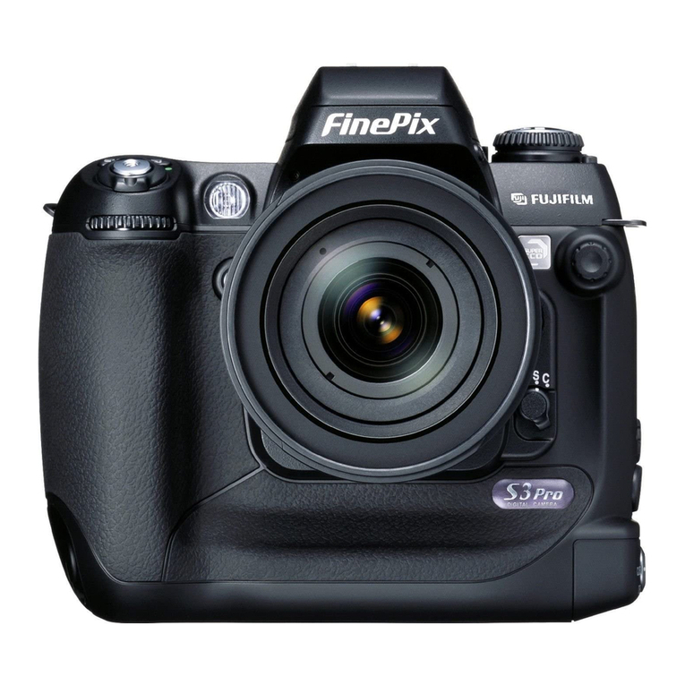
FinePix S2 Pro (U/E) SERVICE MANUAL Table of Contents
CONTENTS
Page
1. General
1-1.Product Specifications ..................................................... 4
1-2.Camera Features .............................................................. 7
1-3.Names of External Components ..................................... 8
2. Disassembly
2-1.Names of internal Components ......................................10
2-2.Removing BATT CART ASSY ......................................... 11
2-3.Removing FRONT CABI .....................................................11
2-4.Removing DSC BLOCK ................................................... 12
2-5.Removing MAIN PWB ASSY...........................................13
2-6.Removing BATT HOLDER ASSY ...................................14
2-7.Removing LCD MONITOR...............................................14
2-8.Removing REAR DISPLAY PANEL................................15
2-9.Removing SW PWB ASSY ..............................................15
2-10.Removing CCD HOLDER ASSY...................................16
2-11.Removing PLATE BOTTOM..........................................17
2-12.Removing GRIP BASE...................................................17
2-13.Removing TOP COVER UNIT....................................... 18
2-14.Removing BODY FPC HARNESS ................................20
2-15.Removing SB LOWER CASE UNIT .............................20
3. Schematic
3-1.Cautions.............................................................................22
3-2.Basic block name and function explanation..................22
3-3.Description of the Main Block Functions .......................22
3-3-1.Overview of the New Technologies.....................22
3-3-2.Block Functions Descriptions...............................23
3-3-3.Description of the Power Supply Block Functions .... 23
3-3-4.Description of the camera body block functions .......23
3-4.Basic block diagram ......................................................... 24
3-5.Overall Connections.........................................................25
3-6.Board mounting diagram ................................................. 26
3-6-1.Printed wiring board of MAIN PWB ASSY..........26
3-6-2.Printed wiring board of SW PWB ASSY............ 27
4. Adjustment
4-1.Checklist for Major Component Replacement ..............28
4-2.
Adjustment Sequence for Major Component Replacement ..
28
4-3.Measuring Instruments Used ..........................................29
4-4.Jigs Used ...........................................................................29
[Modification of an inspection Lens to an adjustment Lens] .......30
4-5.Jig Connection ..................................................................31
4-6.Environment Settings .......................................................31
4-7.Various downloading software decompressions,
preservation methods, and notes ..................................32
4-8.Install the DSC jig driver and the PC adjustment
software ............................................................................34
4-9.Adjustment Software Initial Setup .................................. 35
4-10.Starting the Adjustment Software.................................37
Page
4-11.[F4]: CCD Defect Correction Adjustment ...................38
4-12.[F5]: CAM Adjustment....................................................40
4-13.[F1]: Battery Voltage Adjustment Adjustment.............42
4-14.[F11]:REAR DISPLAY PANEL Adjustment..................44
4-15.[F7]: Flash Adjustment................................................... 45
4-16.[F6]: AF Adjustment .......................................................46
4-17.[F8]: Downloading Firmware .........................................51
4-18.[F12]: End Setting...........................................................53
4-19.Specifying the CAMERA BODY Setting When
Requesting Nikon Repairs.............................................. 57
5. Inspection
5-1.Measuring Instruments and Jigs Used for Inspection..........60
5-2.Connection of Measuring Instruments for Inspection ..........60
5-3.Inspection and Settings at Shipment .............................60
5-4.Resolution Checking ........................................................64
5-5.CCD Cleaning and Inspection Procedures.................... 65
5-5-1.
CCD Cleaning Using a Visual Inspection for Dusting ....
65
5-5-2.
CCD Cleaning Using Test Photography to Detect Dusting
66
5-6.AF Checking......................................................................67
5-6-1.Measuring equipment and tools used for AF checking ...... 67
5-6-2.Settings for the measuring equipment and tools
used for AF checking ............................................67
5-6-3.AF testing procedure............................................. 68
5-6-4.Cause identification procedure for focus-related
problems .................................................................69
6. Parts List
6-1. U-Model ............................................................................70
6-1-1. Packing and Accessories (U)..............................70
6-1-2.CAMERA BODY (U) ..............................................71
6-1-3. Cabinet R (U)........................................................72
6-1-4. Internal (U) ............................................................ 73
6-1-5. TOP COVER (1) (U)............................................. 74
6-1-6. TOP COVER (2) (U)............................................. 75
6-1-7. CAMERA BODY External (U) .............................76
6-2. E-Model.............................................................................77
6-2-1. Packing and Accessories (E)..............................77
6-2-2.CAMERA BODY (E) ..............................................78
6-2-3. Cabinet R (E) ........................................................79
6-2-4. Internal (E) ............................................................80
6-2-5. TOP COVER (1) (E).............................................81
6-2-6. TOP COVER (2) (E).............................................82
6-2-7. CAMERA BODY External (E)..............................83
6-4.Electrical Parts(U)(E) .......................................................84
6-5.Transportation box of camera body repair ....................85
7. Appendix
7-1.List of Related Technical Updates Issued.....................86
