Fujitsu Siemens Computers B17-2 User manual

FSC B17-2
Page 1 of 55
SERVICE MANUAL
FSC MONITOR
B17-2
THESE DOCUMENTS ARE FOR REPAIR SERVICE INFORMATION ONLY.EVERY
REASONABLE EFFORT HAS BEEN MADE TO ENSURE THE ACCURACY OF THIS MANUAL;
WE CANNOT GUARANTEE THE ACCURACY OFTHIS INFORMATION AFTER THE DATE OF
PUBLICATION AND DISCLAIMS RELIABILITY FOR CHANGES, ERRORS OR OMISSIONS.
MANUFACTURE DATA :JUN-20-2005

FSC B17-2
Page 2 of 55
Table Contents
1. MONITOR SPECIFICATIONS ..................................................................................................................................................5
2. LCD MONITOR DESCRIPTION...............................................................................................................................................6
3. OPERATING INSTRUCTIONS .................................................................................................................................................7
3.1 GENERAL INSTRUCTIONS................................................................................................................................................7
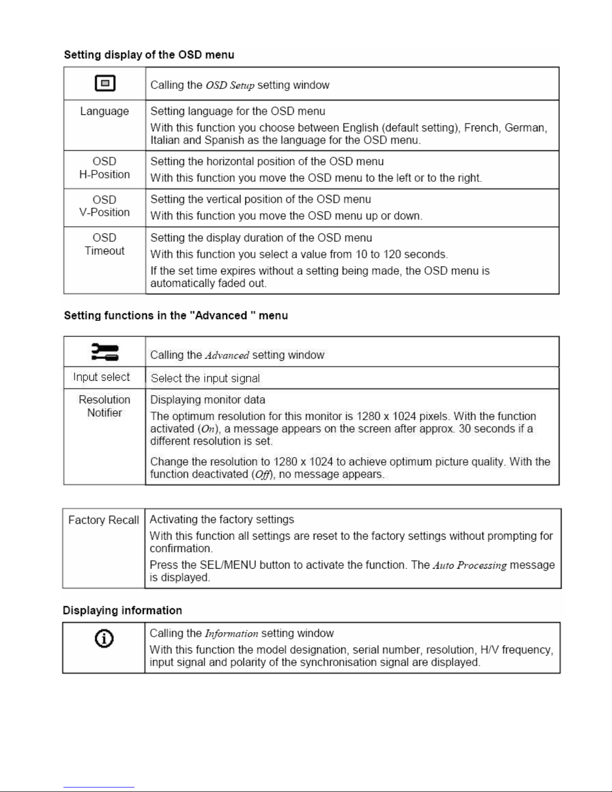
3.2 CONTROL BUTTON.............................................................................................................................................................7
3.3 ADJUSTING THE PICTURE................................................................................................................................................7
4. INPUT/OUTPUT SPECFICATION.......................................................................................................................................... 11
4.1 INPUT SIGNAL CONNECTOR..........................................................................................................................................11
4.2 FACTORY PRESET DISPLAY MODES:.......................................................................................................................12
4.3 POWER SUPPLY FEATURES (ROOM TEMPERATURE 25℃±4℃)..........................................................................14
4.4 PANEL SPECIFICATION ..............................................................................................................................................14
4.4.1 GENERAL SPECIFICATION.....................................................................................................................................14
4.4.2 OPTICAL CHARACTERISTICS ...............................................................................................................................14
4.4.3 BACKLIGHT UNIT ......................................................................................................................................................15
5. BLOCK DIAGRAM ...................................................................................................................................................................17
5.1 MONITOR EXPLODED VIEW...........................................................................................................................................17
5.2 SOFTWARE FLOW CHART..............................................................................................................................................18
5.3 ELECTRICAL BLOCK DIAGRAM.....................................................................................................................................20
5.3.1 SCALAR BOARD BLOCK DIAGRAM......................................................................................................................20
5.3.2 INVERTER/POWER BOARD BLOCK DIAGRAM .................................................................................................21
6. SCHEMATIC ..............................................................................................................................................................................22
6.1 MAIN BOARD ......................................................................................................................................................................22
6.2 INVERTER BOARD ............................................................................................................................................................28
6.3 AUDIO BOARD....................................................................................................................................................................30
7. PCB LAYOUT.............................................................................................................................................................................31
7.1 MAIN BOARD ......................................................................................................................................................................31
7.2 KEY BOARD ........................................................................................................................................................................32
7.3 PWPC BOARD ....................................................................................................................................................................32
8. MAINTAINABILITY.................................................................................................................................................................33
8.1 EQUIPMENT AND TOOLS REQUIREMENT ..................................................................................................................33
8.2 TROUBLE SHOOTING ......................................................................................................................................................34
8.2.1 MAIN BOARD..............................................................................................................................................................34
8.2.2 INVERTER BOARD......................................................................................................................................................37
8.2.3 KEY PAD BOARD ........................................................................................................................................................39
9.WHITE-BLANCE, LMINANCE ADJUSTMENT ...................................................................................................................40
10. EDID CONTENT......................................................................................................................................................................41

FSC B17-2
Page 3 of 55
11. BOM LIST .................................................................................................................................................................................42

FSC B17-2
Page 4 of 55
Revision List
Revision Date Change Description
A00 Feb-19-2005 Initial release
A01 Jun-08-2005
A02 Jun-20-2005

FSC B17-2
Page 5 of 55
1. MONITOR SPECIFICATIONS
Monitor Modes FSC B17-2
Type 17.0” TFT
MAX Display Area 337.9mm×270.3mm (W×H)
MAX Resolution 1280×1024
Dot Pitch 0.264mm×0.264mm
Colour 16,2 MHz (6bits)
Contrast 500:1
Brightness 300cd/m2
Response Time 8ms
Viewing Angle CR>10 H: 150°; V: 130°
Horizontal Frequency 30~83kHz
Vertical Frequency 55~75 Hz
Input Signal RBG ANALOG SIGNAL(D-sub15)
DIGITAL SIGNAL (DVI 24)
Signal Standard VESA DPMS
Drug & play VESA DDC2B
Picture control OSD
Power Consumption Max 42W(in save modes less than 2W)
Power AC90V~264V
Dimension 373.6mm × 439mm× 248.7mm (W×H×D)
Weight 5.7kg
Operating temperature 5℃~40℃
Operating humidity 10%~85%
Storing temperature 5℃~40℃
Storing humidity 5%~85%
Transport temperature -20℃~60℃
Transport humidity 15%~98%

FSC B17-2
Page 6 of 55
2. LCD MONITOR DESCRIPTION
The LCD MONITOR will contain a main board, a PWPC board, an audio board and a keypad board which house the
flat panel control logic, brightness control logic and DDC.
The power board will provide AC to DC Inverter voltage to drive the backlight and the main board chips each voltage.
Video signal, DDC
PWPC Board
(Contains Adapter, Inverter)
Flat Panel and
CCFL backlight
Main Board
Keyboard
RS232 Connector
For white balance
adjustment in factory
mode
HOST Computer
CCFL Drive.
AC IN
90V ~ 264V
Monitor Block Diagram
Audio board

FSC B17-2
Page 7 of 55
3. OPERATING INSTRUCTIONS
3.1 GENERAL INSTRUCTIONS
Press the power button to turn the monitor on or off. The other control buttons are located in the front of the monitor. By
changing these settings, the picture can be adjusted to your personal preferences.
-The power cord should be connected.
-Connect the video cable from the monitor to the video card.
-Press the power button to turn on the monitor, the power indicator will light up.
3.2 CONTROL BUTTON
3.3 ADJUSTING THE PICTURE

FSC B17-2
Page 8 of 55

FSC B17-2
Page 9 of 55

FSC B17-2
Page 10 of 55

FSC B17-2
Page 11 of 55
4. INPUT/OUTPUT SPECFICATION
4.1 INPUT SIGNAL CONNECTOR
PIN NO. DESCRIPTION PIN NO. DESCRIPTION
1. Red Video 9. +5V input
2. Green Video 10. Logic Ground
3. Blue Video 11. Monitor Ground
4. N / C 12. DDC-Serial Data
5. DDC-Return 13. H-Sync.
6. Red Ground 14. V-Sync.
7. Green Ground 15. DDC-Serial Clock
8. Blue Ground
VGA Connector layout
15
610
11 15
1 TX2- 9 TX1- 17 TX0-
2 TX2+ 10 TX1+ 18 TX0+
3 Shield (TX2 / TX4) 11 Shield (TX1 / TX3) 19 Shield (TX0 / TX5)
4 TX4- 12 TX3- 20 TX5-
5 TX4+ 13 TX3+ 21 TX5+
6 DDC-Serial Clock 14 +5V power 22 Shield (TXC)
7 DDC-Serial Data 15 Ground (H/V sync) 23 TXC+
8 V-Sync. (analog) 16 Hot plug detect 24 TXC-
Pin - Assignment of DVI-D connector:

FSC B17-2
Page 12 of 55
4.2 FACTORY PRESET DISPLAY MODES:
Factory preset no. 1234
H-Resolution
V-Resolution
Pixel clock
H-Frequency
V-Frequency
Interlace
[px]
[Lines]
[MHz]
[kHz]
[Hz]
720
400
28.325
31.472
70.1
NONE
640
480
25.175
31.469
59.94
NONE
640
480
31.500
37.861
72.81
NONE
640
480
31.500
37.500
75.0
NONE
800
600
36.000
35.156
56.25
NONE
800
600
40.000
37.879
60.3
NONE
800
600
50.000
48.077
72.2
NONE
H-Sync-polarity
V-Sync-polarity
-
+
-
-
-
-
-
-
+
+
+
+
+
+
H-total
H-active display
H-blanking
H-Front porch
H-Sync-width
H-Back porch
[µs]
[dots]
[µs]
[dots]
[µs]
[dots]
[µs]
[dots]
[µs]
[dots]
[µs]
[dots]
31.774
900
25.419
720
6.355
180
0.635
18
3.813
108
1.906
54
31.778
800
25.422
640
6.356
160
0.636
16
3.813
96
1.907
48
26.413
832
20.317
640
6.095
192
0.762
24
1.270
40
4.063
128
26.667
840
20.317
640
6.349
200
0.508
16
2.032
64
3.810
120
28.444
1024
22.222
800
6.222
224
0.667
24
2.000
72
3.556
128
26.400
1056
20.000
800
6.400
256
1.000
40
3.200
128
2.200
88
20.800
1040
16.000
800
4.800
240
1.120
56
2.400
120
1.280
64
V-total
V-active display
V-blanking
V-Front porch
V-Sync-width
V-Back porch
[ms]
[Lines]
[ms]
[Lines]
[ms]
[Lines]
[ms]
[Lines]
[ms]
[Lines]
[ms]
[Lines]
14.267
449
12.710
400
1.557
49
0.413
13
0.064
2
1.080
34
16.683
525
15.253
480
1.430
45
0.318
10
0.064
2
1.049
33
13.735
520
12.678
480
1.057
40
0.238
9
0.079
3
0.740
28
13.333
500
12.800
480
0.533
20
0.027
1
0.080
3
0.427
16
17.778
625
17.067
600
0.711
25
0.028
1
0.057
2
0.626
22
16.579
628
15.840
600
0.739
28
0.026
1
0.106
4
0.607
23
13.853
666
12.480
600
1.373
66
0.770
37
0.125
6
0.478
23
Expansion Rate hor. 1.78 2.0 2.0 2.0 1.6 1.6 1.6
vert. 2.56 2.13 2.13 2.13 1.71 1.71 1.71
VGA VGA VESA VESA VESA VESA VESA
Factory preset no. 5 6 7 8 9
H-Resolution [px] 800 1024 1024 1024 1280 1280

FSC B17-2
Page 13 of 55
V-Resolution Pixel
clock H-Frequency
V-Frequency
Interlace
[Lines]
[MHz]
[kHz]
[Hz]
600
49.500
46.875
75.0
NONE
768
65.000
48.363
60.0
NONE
768
75.000
56.476
70.1
NONE
768
78.750
60.023
75.0
NONE
1024
108.0
63.981
60.0
NONE
1024
135.0
79.976
75.0
NONE
H-Sync-polarity
V-Sync-polarity +
+
-
-
-
-
+
+
+
+
+
+
H-total
H-active display
H-blanking
H-Front porch
H-Sync-width
H-Back porch
[µs]
[dots]
[µs]
[dots]
[µs]
[dots]
[µs]
[dots]
[µs]
[dots]
[µs]
[dots]
21.333
1056
16.162
800
5.172
256
0.323
16
1.616
80
3.232
160
20.677
1344
15.754
1024
4.923
320
0.369
24
2.092
136
2.462
160
17.707
1328
13.653
1024
4.053
304
0.320
24
1.813
136
1.920
144
16.660
1312
13.003
1024
3.657
288
0.203
16
1.219
96
2.235
176
15.630
1688
11.852
1280
3.778
408
0.444
48
1.037
112
2.296
248
12.504
1688
9.481
1280
3.022 408
0.119
16
1.067 144
1.837 248
V-total V-active
dis-play V-blanking
V-Front porch
V-Sync-width
V-Back porch
[ms]
[Lines]
[ms]
[Lines]
[ms]
[Lines]
[ms]
[Lines]
[ms]
[Lines]
[ms]
[Lines]
13.333
625
12.800
600
0.533
25
0.021
1
0.064
3
0.448
21
16.666
806
15.880
768
0.786
38
0.062
3
0.124
6
0.600
29
14.272
806
13.599
768
0.673
38
0.053
3
0.106
6
0.513
29
13.328
800
12.795
768
0.533
32
0.017
1
0.050
3
0.466
28
16.661
1066
16.005
1024
0.656
42
0.016
1
0.047
3
0.594
38
13.329
1066
12.804
1024
0.525
42
0.013
1
0.038
3
0.475
38
Expansion Rate hor. 1.6 1.25 1.25 1.25 1.0 1.0
vert. 1.71 1.33 1.33 1.33 1.0 1.0
VESA VESA VESA VESA VESA VESA

FSC B17-2
Page 14 of 55
4.3 POWER SUPPLY Features (ROOM TEMPERATURE 25 ±4 )℃℃
• A/C Line voltage range: 90 V - 264 V
• A/C Line frequency range: 47 Hz - 63 Hz
• Current: 1.5 A max. at 100V 0.7 A max. at 240V
• Peak surge current: < 30 A (50A) peak at 240 V AC and cold starting
• Leakage current: < 1.5 mA for power from PC-outlet
< 2.5 mA for power from Wall-outlet
• Power line surge: No adverse effects (no loss of information or defect) with a maximum of 1
half wave missing per second
• Power factor correction: According to EN 61000-3-2 or power consumption is < 75W
4.4 PANEL SPECIFICATION
4.4.1 GENERAL SPECIFICATION
Parameter Specifications Unit
Display size 43 (17”) Diagonal cm
Active area 337.9mm × 270.3mm (W×H) mm
1280 × 1024 (W×H) Pixel
Pixel format
(1 pixel = R + G + B dots)
pixel pitch 0.264mm × 0.264mm (W×H) mm
Pixel configuration RGB Vertical stripe
Display mode Normally White
Unit outline dimensions 358.5 × 296.5 × 16.5 mm
Weight 2000 g
Surface treatment Anti-glare and hard-coating 3h Low reflection
Lamp quantity 4 pcs
4.4.2 OPTICAL CHARACTERISTICS
The optical characteristics are measured under stable conditions at 25 (Room Temperature):℃

FSC B17-2
Page 15 of 55
4.4.3 BACKLIGHT UNIT


FSC B17-2
Page 17 of 55
5. BLOCK DIAGRAM
5.1 MONITOR EXPLODED VIEW

FSC B17-2
Page 18 of 55
5.2 SOFTWARE FLOW CHART
1
2
N
Y
5
Y
N
10
Y
N
12
Y
N
7
Y
N
6
4
3
8
9
14
11
13
Y
N
1
5
Y
N
16
1
7
19
Y
N
18

FSC B17-2
Page 19 of 55
1). MCU initialize.
2). Is the eeprom blank?
3). Program the eeprom by default values.
4). Get the PWM value of brightness from eeprom.
5). Is the power key pressed?
6). Clear all global flags.
7). Are the AUTO and SELECT keys pressed?
8). Enter factory mode.
9). Save the power key status into eeprom. Turn on the LED and set it to green color. Scalar initialize.
10). In standby mode?
11). Update the life time of back light.
12). Check the analog port, are there any signals coming?
13). Does the scalar send out an interrupt request?
14). Wake up the scalar.
15). Are there any signals coming from analog port?
16). Display "No connection Check Signal Cable" message. And go into standby mode after the message
disappear.
17). Program the scalar to be able to show the coming mode.
18). Process the OSD display.
19). Read the keyboard. Is the power key pressed?

BU1527
Page 20 of 55
5.3 ELECTRICAL BLOCK DIAGRAM
5.3.1 SCALAR BOARD BLOCK DIAGRAM
OSD
Control Interface
(KEYPAD)
Scalar TSU16AK
(Include ADC, OSD)
(U401)
MCU
(U601)
EEPROM
(U602)
D-Sub Connector
(CN301)
EEPROM
(U301)
Hsync,
Vsync
R
G
B
RXD
TXD
DB15_SDA
DB15_SCL
EPR_SDA
EPR_SCL
Panel Interface
(CN503)
DVI Connector
(CN302)
EEPROM
(U302)
DVI_SDA
DVI_SCL
Table of contents
Popular Car Video System manuals by other brands

Alpine
Alpine Multimedia Manager PXA-H900 Guide for installation and connections

Audiovox
Audiovox VMO 5020 V owner's manual

Polaroid
Polaroid Overhead DVD Player user manual

DICE
DICE MediaBridge MB-1500-BMW Installation guide & user manual

ZENEC
ZENEC Z-R1030 user manual

Boss Audio Systems
Boss Audio Systems BV9995B user manual