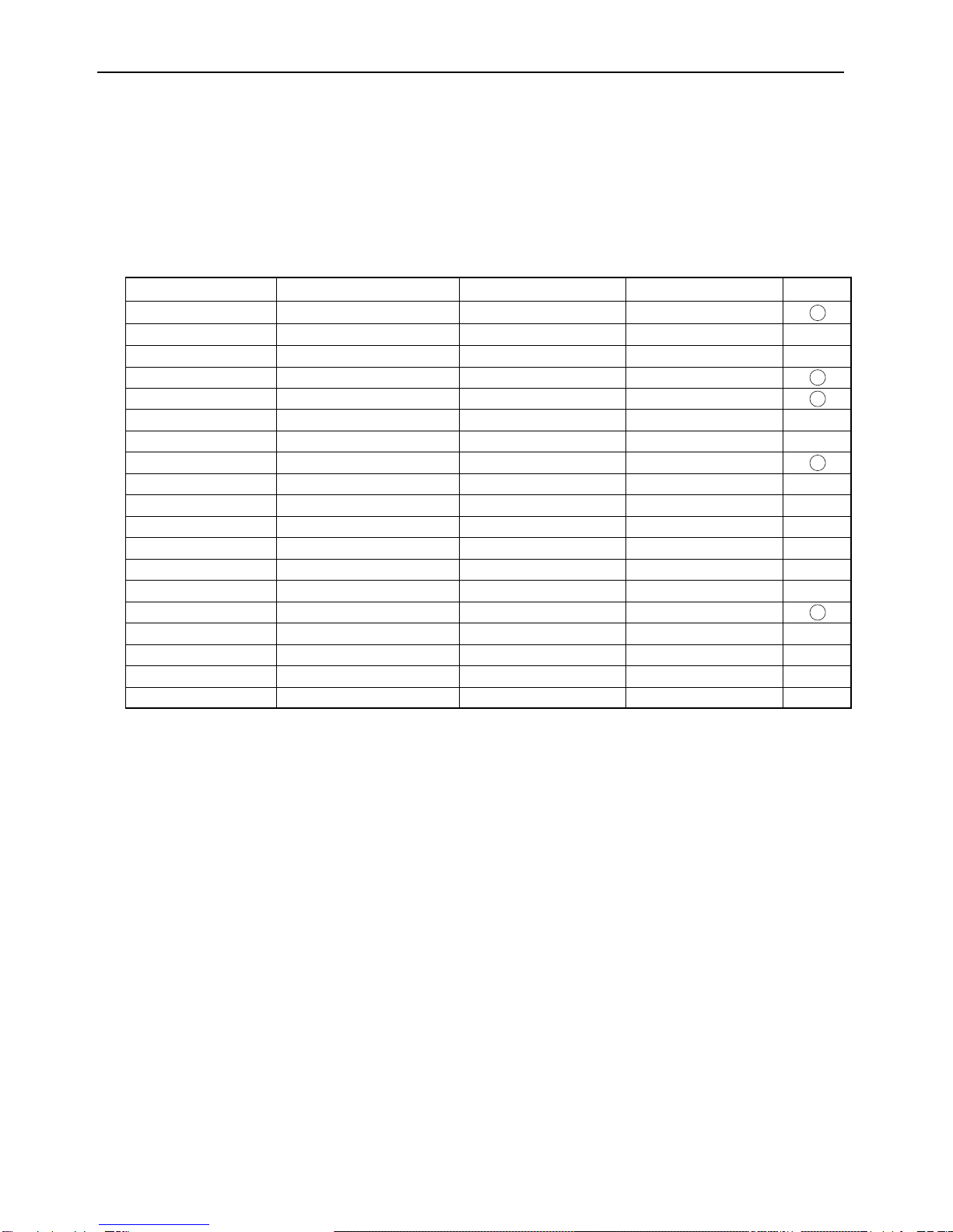
Fujitsu P50XHA10US User manual

P50XHA10US
Copy Prohibited
FUJITSU GENERAL Proprietary

- 4 -
SPECIFICATIONS
Power requirement 120V, 50/60Hz (U Type)
220-240V, 50/60Hz (W, E Type)
Current drain 4.9A (U Type)
2.7A-2.2A (W, E Type)
Display panel
Screen size 110.6 (W) x 62.2 (H) [cm]
43.5 (W) x 24.5 (H) [inch]
Aspect ratio 16 : 9
Number of pixels 1,366 (H) x 768 (V) pixels
Pixel pitch 0.81mm x 0.81mm
Contrast ratio 3000 : 1
Luminance 600 cd/m2
Viewing angle Max. 160 degrees
Input Terminals
RS-232C D-sub 9 pin terminal
Color system
NTSC/PAL/SECAM/N-PAL/M-PAL
/4.43NTSC/PAL60
Display colors
16.7 million (256 each for R.G.B.)
Outer dimensions Width : 121.4cm (47.8 inch)
Height: 72.8cm (28.7 inch)
Depth : 9.8 cm ( 3.9 inch)
Net weight 45.0kg
Environment (Operating)
Temperature 0 to 40 C
Relative humidity 20 to 80%
Pressure 850 to 1,114 hPa
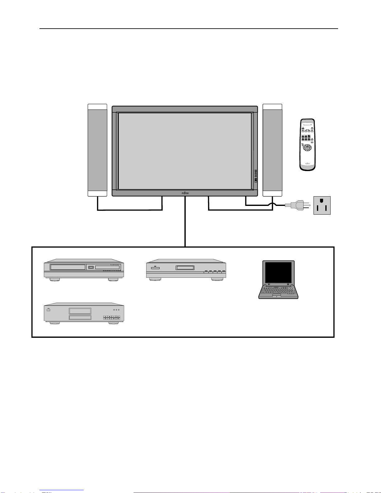
Accessories User's manual
Remote controller
Batteries (Type AA x 2)
Power cord
Big ferrite core (2)
Small ferrite core (2)
Options
Stand P-TT5000
P-WB5000Wall mounting unit
P-CT5000
0 to 15 mounting angle
Ceiling mounting unit
P-SP5000Speaker
P-ST5000Speaker stand
Standards
P50XHA10WS P50XHA10ES
P50XHA10US
AS
Safety : IEC60065
EMC : AS/NZS 3548 AS/NZS 3548
CE
Safety: EN60065
UL,CSA
Safety:
UL6500
C-UL
EMC: FCC Part15 Class A
ICES-003 Class A
UL6500
C-UL
FCC Part15 Class B
ICES-003 Class B
EMC : EN55022 1998
Class A
EN61000-3-2 1995
EN61000-3-3 1995
EN55024 1998
EN61000-4-2 1995
EN61000-4-3 1996
EN61000-4-4 1995
EN61000-4-5 1995
EN61000-4-6 1996
EN61000-4-8 1993
EN61000-4-11 1994
EN60065
EN55022 1998
Class B
EN61000-3-2 1995
EN61000-3-3 1995
EN55024 1998
EN61000-4-2 1995
EN61000-4-3 1996
EN61000-4-4 1995
EN61000-4-5 1995
EN61000-4-6 1996
EN61000-4-8 1993
EN61000-4-11 1994
0 to 15 mounting angle
Video input
(E model:option)
(E model:option)
RCA terminal
1.0VP-P /75Ω
Video input
Video
(only E model:option)
(only E model)
SCART terminal
1.0VP-P /75Ω
S video input
S video
RGB
S terminal
Y signal:1.0VP-P /75Ω
C signal:0.286VP-P /75Ω
Y signal:1.0VP-P /75Ω
C signal:0.286VP-P /75Ω
Component Three RCA terminals
(one system)video input
Y : 1.0VP-P /75Ω
G : 0.7VP-P /75Ω
B : 0.7VP-P /75Ω
R : 0.7VP-P /75Ω
Pb/B-Y: 0.7VP-P /75Ω
Pr/R-Y: 0.7VP-P /75Ω
Analog RGB 2 input mD-sub:15pin (3 row type)
Video : 0.7VP-P /75Ω
SYNC signal : TTL level
Analog RGB 3 input BNC terminal x 5
R: 0.7VP-P/75Ω
G: 0.7VP-P/75Ω
B: 0.7VP-P/75Ω
H: TTL level or 0.3VP-P /75Ω
V: TTL level or 0.3VP-P /75Ω
User set mode 8 memories (each RGB1,2,3)
Display frequency Horizontal :15.63 to 80.0MHz
Vertical : 50.0 to 120Hz
Dot clock:50MHz Max
XGA 68MHz
Digital RGB 1 input DVI-D terminal (HDCP)
Analog audio input Two RCA terminals(one system)
500mVrms/22kΩ
Effective max.
Level terminal 12W+12W (L/R), 6
Ω
output
Differential Input 0.5V 10%
(RXC , RX0 , RX1 , RX2 )
+
+ + + +
IEC60065

SETTING SIGNALS
- 5 -
This display can store parameter settings for eight additional signals for RGB.
To do this, select the desired signal and follow "RGB MODE ADJUSTMENT" in the manual to adjust the parameters.
When you finish, the settings will be automatically stored.
FACTORY SET SIGNALS (RGB MODE)
Main corresponding signals (RGB mode)
* With some input signals, “Out of range” may appear even when the horizontal and vertical frequencies are within their permissible ranges. Make
sure that the vertical frequency of the input signal is 85 Hz or less for SVGA, 75 Hz or less for XVGA/ SXGA , 60 Hz or less for UXGA.
640 x 480 31.47 59.94 VGA
640 x 480
640 x 480
37.50 75.00 VGA 75 Hz
43.27 85.01 VGA 85 Hz
720 x 400 31.47 70.09 400 lines
800 x 600 37.88 60.32 SVGA 60 Hz
800 x 600
800 x 600
46.88 75.00 SVGA 75 Hz
53.67 85.06 SVGA 85 Hz
1024 x 768
48.36 60.00 XGA 60 Hz
1024 x 768
1024 x 768
1024 x 768
60.02
68.68
75.03
84.99
XGA 75 Hz
XGA 85 Hz
1280 x 1024 63.98 60.02 SXGA 60 Hz
1280 x 1024 79.98 75.03 SXGA 75 Hz
1600 x 1200 75.00 60.00
106.25 85.00 UXGA 85 Hz
UXGA 60 Hz
1600 x 1200
1360 x 768
848 x 480 31.02 60.00
852 x 480 31.72
47.71
59.97
60.01
720 x 485 15.73 59.94 60 fields
720 x 575 15.63 50.00 50 fields
Signal DVD-I
Display (dots x lines) Horizontal frequency (kHz) Vertical frequency (Hz)

- 8 -
EXAMPLE OF CONNECTION TO EXTERNAL COMPONENTS
Remote
control
Display Speaker (optional)
Speaker
VCR
DVD player
Satellite tuner
PC
CONNECTION

[MODE]
Input mode selector button
Power indicator lamp
Remote control signal receiver
Input mode selector button
[MODE]
Switches between picture input modes.
VOL + button
VOL - button
Adjusts the sound volume.
Wide screen selector button [WIDE]
Switches the screen over to a desired wide screen.
ON/OFF button
Turns the power "ON" and "OFF (standby state)".
(Right section)
Control Panel (Right side of display)
DISPLAY SECTION – FRONT
This lamp shows the state of the power supply.
Lit (red): Stand-by
Lit (green): Power ON
Lit (orange): Power saving (DPMS: Power saving
Flashing (red): Malfunction (Flashes differently depending
function) mode ON
on the type of malfunction.)
Receives signals from the remote control.
PART NAMES AND FUNCTIONS
- 18 -

- 23 -
VIDEO MODE ADJUSTMENT
MENU
ENTER
VIDEO 1
Normal
Wide 1
Wide 2
Position Horizontal "-"
Horizontal "+"
Vertical "-"
Vertical "+"
Size Width "-"
Width "+"
Height "-"
Height "+"
Zoom 1
Zoom 2
PICTURE
POSITION/SIZE
REMOTE CONTROLLER
VIDEO 2
VIDEO 3
RGB 1
RGB 3 / VIDEO 4
RGB 2
VOL. +
VOL. -
MUTE
DISPLAY
PICTURE MODE Dynamic
Fine
Real 1
Real 2
Static
PICTURE MEMORY
WIDE
Dynamic
Fine
Real 1
Real 2
Static
Off
Min.
Std.
Max.
Off
5
10
15
Off
On
Horizontal {-30 to +30 (Comp. video -16 to +16)}
{-7 to +12 (Comp. video -4 to +16)}
{-6 to +6}
{-6 to +6}
{-10 to +10}
{-7 to +12 (Comp. video -4 to +16)}
{-7 to +7 (Zoom -15 to +15) (Comp. video -16 to +16)}
Vertical
Contrast {-30 to +30}
{-30 to +30 (Comp. video -60 to +60)}
{-16 to +16}
{-60 to +60}
{-60 to +60}
Brightness
Color
Tint
Sharpness
Picture Mode
Precision Setting
Picture Memory
Noise Reduction
Normal
Auto
Wide 1
Wide 2
Zoom 1
Zoom 2
FEATURES
Function
On Screen Menu
Input Terminal
Others
AUDIO
Luminance {40 to 100%}
{-15 to +15}
{-3500 to +3500}
Can be set when Fine is
selected as the Picture Mode.
Black Level
Colour Temp.
User Color Temp.
DVI Input
Audio Input
OSD
Language
Name Select
24 Frame Mode
FACTORY DEFAULT
Treble
Bass
Balance
Loudness
Load
Save
Execute
Position
Adjustment* Clamp Position* *Only Comp. Video{-8 to +8}
Size Width
Height
Yes
No
Default
White Screen
Yes
No
Yes
No
Default
Red {0 to 255}
{0 to 255}
{0 to 255}
Green
Blue
On
Off
DVI 1
DVI 2
On
Off
On
Off
Mode
Freq. Scan Mode
Input Signal
Freq.
On(OSD : bright)
On(OSD : dark)
Off
}
Exhibition Mode
Information
Memory 1
Memory 2
Memory 3
Memory 4
Memory 5
Memory 6
Memory 7
Memory 8
English
Deutsch
Espanol
Francais
Italiano
Portugues
RGB-PC
Decoder
Video Input
S-video Input
Load
Save
Memory 1
Memory 2
Memory 3
Memory 4
Memory 5
Memory 6
Memory 7
Memory 8
~
~
<
RGB 1
RGB 2
Video 1
Video 2
Video 3
Video 4
Mask
No Audio
Audio 1
Audio 2
Audio 3
RGB 1
PC 1
PC 2
DVD 1
DVD 2
STB
Satellite
Cable TV
Auto 1
Auto 2
NTSC
PAL
SECAM
PAL60
N-PAL
M-PAL
4.43NTSC
Video 1
DVD 1
DVD 2
VCR 1
VCR 2
GAME
Camcorder
STB
Satellite
Cable TV
D-SUB Input
Mask Off
Mask 5
Mask 10
Mask 15
RGB 1
RGB 2
Video 1
Video 2
Video 3
Video 4

- 25 -
1. Display
(1) OSD
Three kinds of error messages are displayed on the screen, and the power is turned off 10 sec later.
(2) LED
LED error is displayed continuously after the power is turned off.
2. Error types and check points
On screen display Cause Check point
ERROR MESSAGE CONDITION 1 Fan protector operated Fan
Main/Digital PCB
ERROR MESSAGE CONDITION 2 Temperature protector
operated
Ambient temperature of unit
Main/Digital PCB
Temp. sensor IC757
(1) OSD
LED lamp display status Cause Check point
Steady light (Red) Stand-by status
Continuous
Flashes continuously (Red) No power
Power supply protector
operated
Main/Digital PCB
PDP panel
1 time
Flashes once every 4 sec. (Red)
Fan protector operated Fan
Main/Digital PCB
2 times
Flashes twice every 5 sec. (Red)
Temperature protector
operated
Ambient temperature of unit
Temperature sensor IC757
Main/Digital PCB
4 times
Flashes four times every 7 sec. (Red)
Main/Digital circuit faulty Main/Digital PCB
5 times
Flashes five times every 8 sec. (Red)
Video circuit faulty Video PCB Assy
(2) LED
TROUBLESHOOTING USING LED AND OSD

- 32 -
MAIN POWER SELECTOR SWITCH ADJUSTMENT
Adjustment
Note:
Confirm the main voltage set switch is set to 220-240V. (W and E version)
Confirm the main voltage set switch is set to 120V.(U version)
230V covers input AC voltage from 200V till 260V, and 110V covers from
90V till 130V.

- 33 -
EXPLANATION OF LABELS
Panel Label Information
M
No.
Vbk :
Vsus :
Ve :
Vad
MADE IN JAPAN
Panel Production Date
For Example---------1.8.2
18 2
Year Month
9 : 1999 1 : JAN 1 : Beginning of Month(01-10th)
0 : 2000 2 : FEB 2 : Middle of Month (11-20th)
1 : 2001 3 : MAR 3 : End of Month (21-31st)
2 : 2002
9 : SEP
0 : OCT
N : NOV
D : DEC
For Example----------- YA1450001
YA 1 4 5 0001 * MID/AUG/2001
* YA Production Line
1 Production Line No. 4 Production Period (Day)
1st Month
2 Production Year 1 : BEG (1-10)
1 : 2001 2 : MID (11-20)
2 : 2002 3 : END (21-30/31)
2nd Month
3 Production Month 4 : BEG (1-10)
1 : JAN-FEB 5 : MID (11-20)
2 : MAR-APR 6 : END (21-30/31)
3 : MAY-JUN
4 : JLY-AUG 5 Serial Number
5 : SEP-OCT From 0001-----
6 : NOV-DEC
12345
* * *
..
*****V
*****V
:*****V
*****V
**********
*****
1
2
3
4
5
Unit Serial Number
Panel Part Number
Panel Serial Number
Adjustment Voltage

- 34 -
REPLACEMENT PARTS AND REQUIRED ADJUSTMENT
Caution
Preparation
Quick adjustment after PCB replacement
To remove PCB, wait for 1 minute after power was turned off for electrolytic capacitors to discharge.
Wide------------------ Auto
Input------------------ White pattern
PCB Item VR Test Point Level
PFC R548 P24 connector pin 1 400V ±1V
Vsus R639 TPVsus Vsus ±1V
Vda R545 TP117 74V ±1V
Vad R6477 TPVAD Vad ±1V
Vbk R6670 TPVBK Vbk ±5V
Sustain Drive PCB Ve R6829 TPVE VE ±1V
Vsus R639 TPVsus Vsus ±1V
Vad R6477 TPVAD VAD ±1V
Ve R6829 TPVE VE ±1V
Panel Glass
Scan Drive PCB
Power Supply PCB

- 35 -
R6670/Vbk
R6557
Label (Serial Number for Unit) Label (Panel Information)
R6523
R6477/Vad
TPVBK
TPSC1
TPVAD
TP7117/Vda TP7117/Vda
TP7117/Vda TPVSET TP7117/VdaP24 connector pin 1
TPSS1
TPVe
TPVSUS
TPVSCN
R548/PFC S701 120V/220-240V Switch
R639/Vsus
R545/Vda
R6770/Ve
Adjustment VR Location
Test Point Location
VR AND TEST POINT LOCATION

OPTICAL FILTER
PLASMA DISPLAY PANEL UNIT
MD-50HM5
DC/DC
MAIN/DIGITAL
CONNECTION
92 FAN92 FAN
INLET FILTER
AC LINE FILTER
TERMINAL
VIDEO
AUDIO
POWER ON/OFF
SWITCH
AUDIO TERMINAL
M02GOG
M02AF
M02GOA
M01CUA
M02GOB
M02GOC
M02GD
M02GOD
M02GOE
M02GOF
Commo
Commo
Commo
Commo
LED/PHOTO AMP
KEY SWITCH
PHOTO AMP
P50XHA10WS
GENERAL CONNECTION DIAGRAM
- 36 -

Ref.no. Description P50XHA10WS P50XHA10ES P50XHA10US
Cabinet Bezel Front Top 8115002001
Bezel Front Bottom 8115003008
Electric Fan Motor 8900280003
Optical Filter 8113177008
Filter PCB 8115882009
Connection PCB 8115049006 81150490068115204009
DC/DC PCB 8115054000
I/O PCB 8115047002
Power Switch PCB 8115053003
LED/PHOTO PCB 8115051009
Main Digital PCB 8115888001 81158880018115890004
Video PCB 8115842003 8115842003
PDP Unit S141011951
Power Cord VDE 8112527002 -----------
UL.CSA ----------- -----------
-----------
8112528009
Remote Control Unit 8114649016
Panel Glass S141011821
Data Drive (Upper Left) PCB (C1) S141011678
Data Drive (Upper Center) PCB (C2) S141011685
Data Drive (Upper Right) PCB (C3) S141011692
Data Drive (Lower Right) PCB (C4) S141011708
Data Drive (Lower Center) PCB (C5) S141011715
Data Drive (Lower Left) PCB (C6) S141011722
Saving Power PCB (C9) S141011777
Scan Drive Output (Upper) PCB (SU) S141011739
Scan Drive Output (Lower) PCB (SD) S141011746
Scan Drive PCB (SC) S141011807
Sustain Drive Output (Upper) PCB (SS2) S141011753
Sustain Drive Output (Lower) PCB (SS3) S141011760
Sustain Drive PCB (SS) S141011814
Power Supply PCB (P1) S141011791
Digital PCB (D) S141011784
Packing Carton Top 8115025000
Carton Bottom 8112247009
Packing Joint-D 8108655009
Packing Pad-Top 8112248006
Packing Pad-Bottom 8112249003
Bezel Front Right 8115005002
Bezel Front Left 8115004005
Case Rear 8114998008
Audio Connection PCB 8115058008
Audio Main PCB 8115056004
Carton Accessory 8111799004
Insheet 8112260008
: Same as left
- 73 -
PARTS LIST

OPTICAL FILTER
PLASMA DISPLAY PANEL UNIT
MD-50HM5
DC/DC
MAIN/DIGITAL
VIDEO
CONNECTION
92 FAN92 FAN
INLET FILTER
AC LINE FILTER
TERMINAL
AUDIO
POWER ON/OFF
SWITCH
AUDIO TERMINAL
M02GOG
M02AF
M02GC
EURO SCART
(OPTIONAL)
M02GOA
M01CUA
M02GOB
M02GOC
M02GOD
M02GOE
M02GOF
Commo
Commo
Commo
Commo
LED/PHOTO AMP
KEY SWITCH
PHOTO AMP
P50XHA10ES
GENERAL CONNECTION DIAGRAM
- 37 -

OPTICAL FILTER
PLASMA DISPLAY PANEL UNIT
MD-50HM5
DC/DC
MAIN/DIGITAL
CONNECTION
92 FAN92 FAN
INLET FILTER
AC LINE FILTER
TERMINAL
VIDEO
AUDIO
POWER ON/OFF
SWITCH
AUDIO TERMINAL
M02GOG
M02AF
M02GOA
M01CUA
M02GOB
M02GOC
M02GD
M02GOD
M02GOE
M02GOF
Commo
Commo
Commo
Commo
LED/PHOTO AMP
KEY SWITCH
PHOTO AMP
P50XHA10US
GENERAL CONNECTION DIAGRAM
- 38 -

- 26 -
LED lamp blinking
Turn power on and check
state of lamp.
Not lighted.
LAMP STATE
Power supply
PCB faulty.
POWER SUPPLY STATE
Check PDP Panel.
Check PDP Panel.
REMEDY
Power turned off
immediately.
RED
Blinks continuously.
Power turned off
immediately.
RED
Blinks once Power turned off
after 10 sec.
RED Check 1
Blinks twice Power turned off
after 10 sec.
RED Check 2
Blinks four times Power not turned
off, LED blinks only.
RED Replace Main/Digital
PCB Assy.
Blinks five times Power not turned
off, LED blinks only.
RED Replace Video PCB
Assy.
Is on-screen display
normal? Check PDP Panel.
Video PCB faulty.
Video PCB faulty.
Signal processing
PCB faulty.
Replace Main/Digital
PCB Assy.
Replace Main/Digital
PCB Assy.
Replace Video PCB
Assy.
Replace Video PCB
Assy.
Signal processing
PCB faulty.
Check 3
Lights steadily for
more than 10 sec.
GREEN
NO
YES
All input image
faulty.
Video input image
faulty.
S-video input image
faulty.
Component video
input image faulty.
RGB 1, 2 input image
faulty.
Note : 1. Since a voltage is applied to the Main Power
PCB heat sinks while the set is operating, do
not touch the heat sinks.
2. If the Main Power PCB insulation sheet is not
installed when assembling, the Main Power
PCB fuse will blow.
TROUBLESHOOTING FLOWCHART

No
No
Fan protector operated
Power lamp: Flashes once intermittently in red.
(For 0.5 sec. at an interval of 3 sec.)
Check 1
Start
Yes
Is voltage at
connectors P11 1pin,
P13 1pin on Main Power
Supply PCB(TNPA
2516) 14V?
Microcomputer
peripheral
circuit faulty.
∗Replace Main/
Digital PCB Assy.
Temperature protector operated
Power lamp : Flashes intermittently twice in red.
(For 0.5 sec. at an interval of 5 sec.)
Check 2
Start
Adjust PDP unit installation so that
peripheral temperature is 40.0 C or
less.
No
Yes
Is ambient temperature
of IC757 on Main/Digital
PCB less than 60 C ?
Microcomputer
peripheral circuit
faulty.
Yes
Replace
Main/Digital
PCB Assy.
Fan faulty Replace fan.
Temperature
sensor IC757 faulty.
Temperature sensor cooling
The temperature sensor IC757 is installed
on Main/Digital PCB. Turn the power off
and cool with a point cooler.
Replace
temperature sensor
IC757.
Does unit
operate normally
when temperature sensor
IC757 changed ?
- 27 -

Is Sync.
correctly ?
signal input to pin
le ?
Is frequency of horizontal sync.
and vertical sync signals within
specified range ?
Is input level(∗) within specified
range ?
Signal processing circuit faulty.
Replace Main/Digital PCB Assy.
Is Sync. switch
signal input to pin 13 and vertical sync
∗
.
.
No Check input signal.
.
.
RGB input is abnormal.
Power lamp: Lighted green
(10 sec or more)
Start
Separate signal Composite signal
No
Yes
Yes
Yes
Sync.on green signal
Yes
Yes
No No
No
Is RGB
cable pin arrangement
appropriate ?
What kind of
signal is output from signal
source ?
Is composite sync.
signal input to pin 2 of RGB
cable ?
Is composite sync.
signal input to pin 13 of RGB
cable ?
(TLL/ANALOG) selected
Is horizontal sync.
signal input to pin 14 of
RGB cab
Check connection cable.
Check input signal.
Connect RGB cable
to terminal.
Check input signal.
No
Mak
Change sync. switch (TTL/ANALOG)
e sync.signal polarity output
from signal source negative, or make
output impedanceTTL.
Yes
.
.
Is Sync.
signal polarity
negative ?
Note(∗): If the synchronizing signal cannot be identified by
TTL level, it is in the 75Ωterminated state.
Yes (ANALOG)
Yes
Check 3
- 28 -

TROUBLESHOOTING PANEL
The plasma display panel consists of a set of six surfaces and is connected to each PCB.
For that reason, the faulty part of PCB or plasma display panel can be focused depending on its symptom.
Symptom
Check
PCB
1. Digital PCB (D2)
2. Data Drive (U/L) (C1)
3. Data Drive (U/C) (C2)
4. Data Drive (U/R) (C3)
5. Sustain Drive (SS)
1. Main/Digital PCB
2. Digital PCB (D2)
3. Scan Drive (SC)
4. Sustain Drive (SS)
1. Digital PCB (D2)
2. Sustain Drive (SS)
1. Digital PCB (D2)
2. Data Drive (L/R) (C4)
1. Digital PCB (D2)
2. Data Drive (L/C) (C5)
1. Digital PCB (D2)
2. Data Drive (L/L) (C6)
1. Digital PCB (D2)
2. Data Drive (U/L) (C1)
1. Digital PCB (D2)
2. Data Drive (L/R) (C4)
3. Data Drive (L/C) (C5)
4. Data Drive (L/L) (C6)
5. Sustain Drive (SS)
Check
PCB
Check
PCB
Check
PCB
Check
PCB
Check
PCB
Check
PCB
Check
PCB
Symptom
Symptom Symptom
Symptom Symptom
Symptom Symptom
-
29
-

- 30 -
1. Digital PCB (D2)
2. Data Drive (U/C) (C2)
1. Digital PCB (D2)
2. Data Drive (U/R) (C3)
Check
PCB
Check
PCB
Symptom Symptom
1. Saving Power (C9) 1. Saving Power (C9)
Check
PCB
Check
PCB
Symptom Symptom
1. Scan Drive Output (Upper) (SU)
2. Scan Drive (SC)
1. Scan Drive Output (Lower) (SD)
2. Scan Drive (SC)
Check
PCB
Check
PCB
Symptom Symptom
1. Scan Drive Output (Upper) (SU)
2. Display Panel Assy (Glass)
1. Scan Drive Output (Lower) (SD)
2. Display Panel Assy (Glass)
Check
PCB
Check
PCB
Symptom Symptom
1. Data Drive (U/R) (C3)
2. Digital PCB (D2)
3. Display Panel Assy (Glass)
1. Data Drive Power (U/C) (C2)
2. Digital PCB (D2)
3. Display Panel Assy (Glass)
Check
PCB
Check
PCB
Symptom Symptom
Table of contents
Other Fujitsu Plasma TV manuals

Fujitsu
Fujitsu PlasmaVision P42HHA30WS User manual

Fujitsu
Fujitsu MYRICA P42-2 User manual

Fujitsu
Fujitsu Plasmavision P50XHA10WS User manual

Fujitsu
Fujitsu PlasmaVision P42HHA30WS User manual

Fujitsu
Fujitsu AVIAMO P65FT00AUB User manual

Fujitsu
Fujitsu MYRICA P50-2 User manual

Fujitsu
Fujitsu Plasmavision P63XHA30WS User manual

Fujitsu
Fujitsu Plasmavision P42VHA51W SERIES User manual

Fujitsu
Fujitsu Plasmavision PDS4214W-S User manual

Fujitsu
Fujitsu MYRICA P42-1A User manual