Fujitsu Plasmavision P42VHA51W SERIES User manual

English
Before using the display, read this manual carefully so that you know how to use the display correctly.
Refer to this manual whenever questions or problems about operation arise. Be sure to read and observe the safety precautions
(see the separate "Safety Precautions" manual).
Keep this manual where the user can see it easily.
* Installation and removal require special expertise. Consult your product dealer for details.
* When “English” is selected at “Language” of the on-screen display, “colour” will be displayed in the case of the E model and “color”
will be displayed for all other models.
The notation used in this user’s manual is “color”.
* The last digit of MODEL NO. (10 digit alphanumeric characters) indicated on the product means the body color indication alphabet
or the management number.
* The Illustration of external appearance is for 42” model.
Please acknowledge some differences in the actual product of other models.
USER’S MANUAL
WIDE PLASMA DISPLAY
P42VHA51W SERIES
P42HHA51W SERIES
P50XHA51W SERIES
P55XHA51W SERIES
P63XHA51W SERIES
7619_E.book 1 ページ 2006年10月11日 水曜日 午後8時18分

E-2
CONTENTS
INFORMATION ................................................................E-3
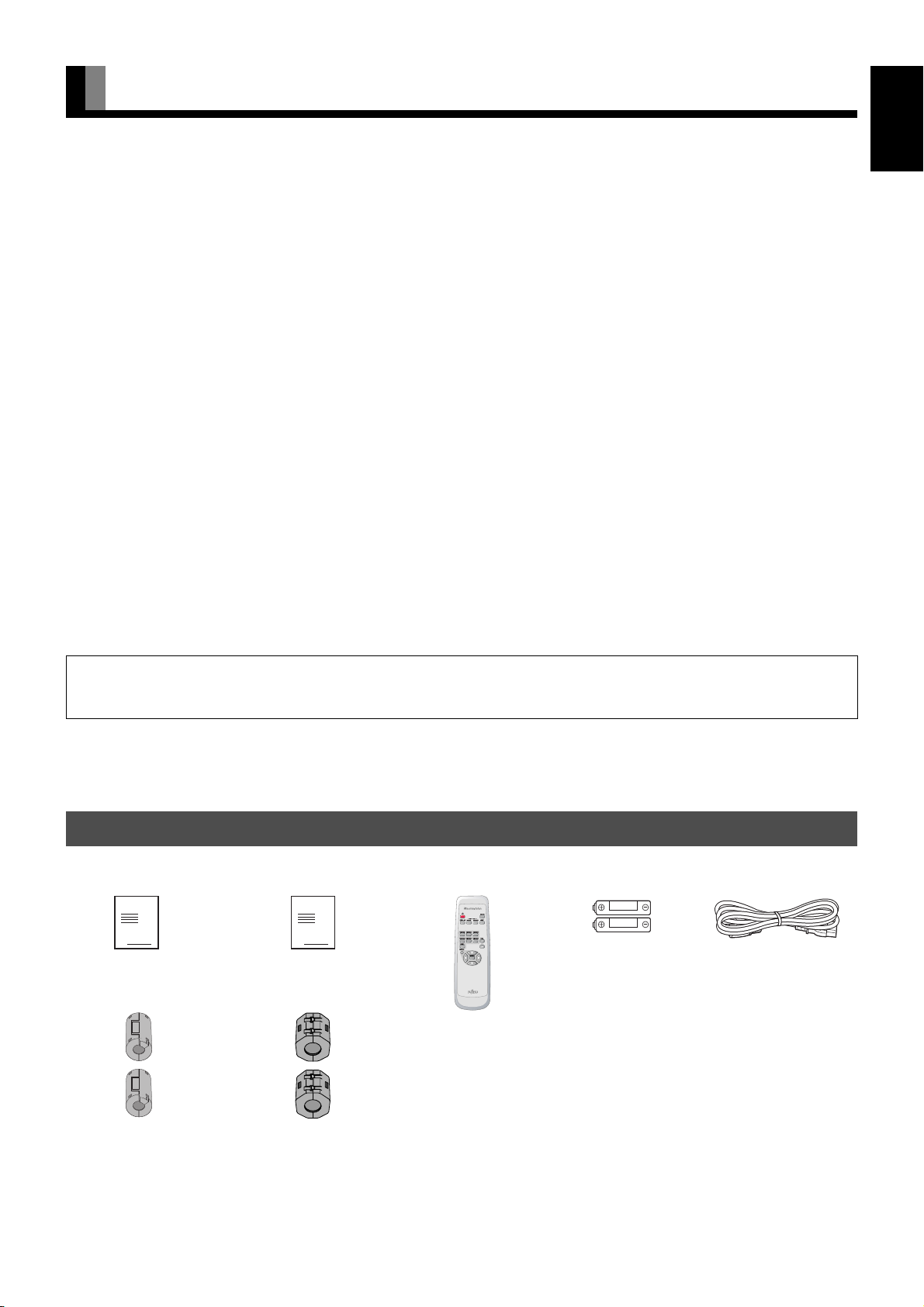
CHECKING ACCESSORIES ................................................E-3
INSTALLATION ...............................................................E-4
ATTACHING THE FERRITE CORES ...................................E-4
PART NAMES AND FUNCTIONS ...................................E-5
DISPLAY SECTION – FRONT .............................................E-5
DISPLAY SECTION – BACK ................................................E-5
DISPLAY SECTION – BOTTOM ..........................................E-6
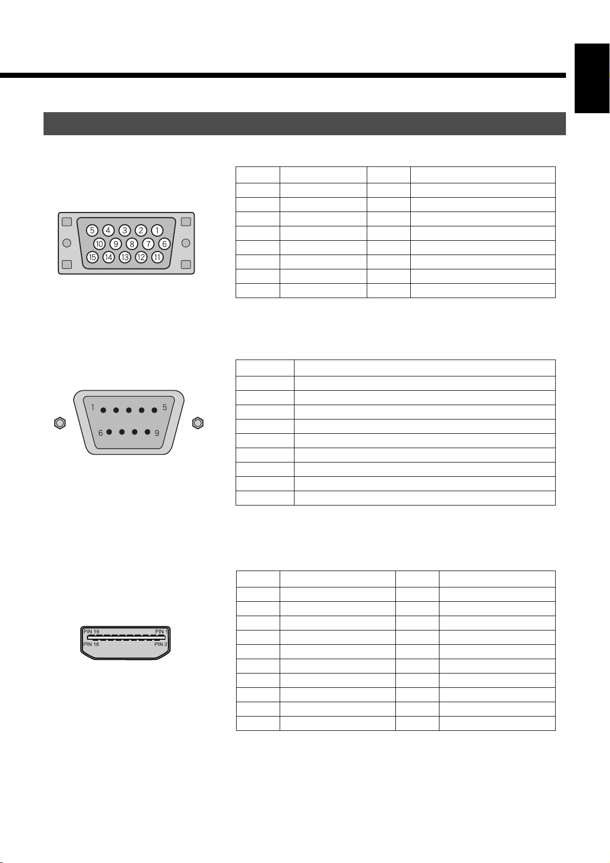
DESCRIPTION OF INPUT TERMINALS ..............................E-7
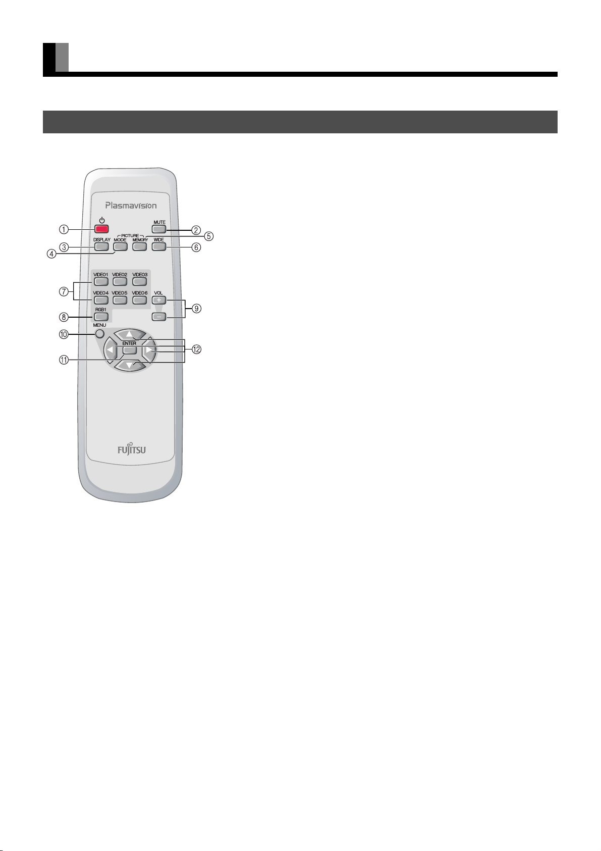
REMOTE CONTROL ............................................................E-8
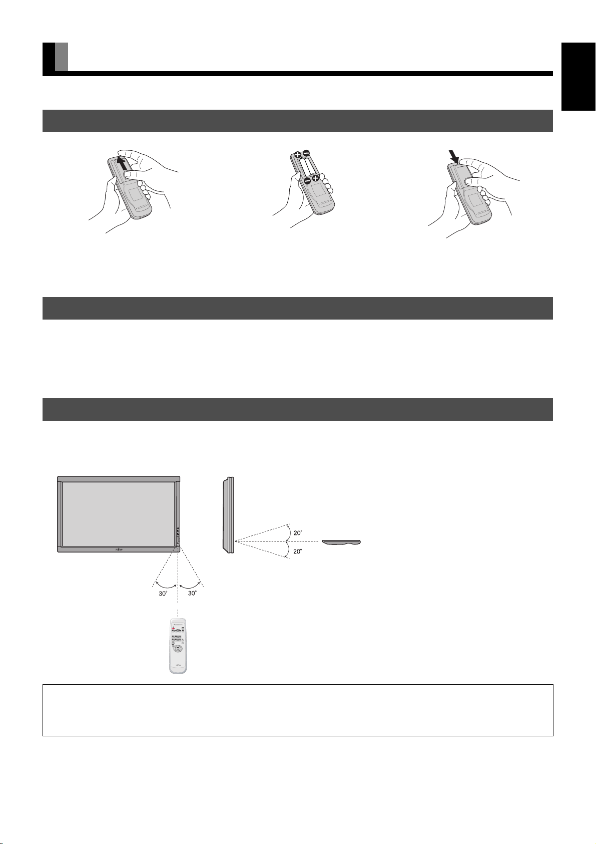
USING THE REMOTE CONTROL...................................E-9
PUTTING BATTERIES IN THE REMOTE CONTROL .........E-9
PRECAUTIONS ....................................................................E-9
EFFECTIVE RANGE FOR THE REMOTE CONTROL .........E-9
CONNECTING THE DISPLAY TO EXTERNAL
EQUIPMENT ..................................................................E-10
DVD RECORDER/PLAYER, SATELLITE TUNER .............E-10
VCR/PC ..............................................................................E-10
BASIC OPERATIONS....................................................E-11
TURNING THE POWER ON AND STAND-BY ...................E-11
ADJUSTING THE VOLUME ...............................................E-11
VIDEO INPUT MODE .........................................................E-11
RGB INPUT MODE .............................................................E-12
CONVENIENT FUNCTIONS ..............................................E-12
On-screen information ..................................................E-12
Picture Mode ................................................................E-12
Picture Memory ............................................................E-12
WATCHING PICTURES ON THE WIDE SCREEN........E-13
SWITCHING BETWEEN SCREEN SIZES .........................E-13
SCREEN SIZE ....................................................................E-14
ASPECT RATIO ..................................................................E-14
ADJUSTMENT MENU ...................................................E-15
BASIC PROCEDURE OF ADJUSTMENT MENU .........E-16
ADJUSTING THE PICTURE..........................................E-17
Signal Contrast ...................................................................E-17
Drive Contrast .....................................................................E-17
Brightness ...........................................................................E-17
Color ...................................................................................E-17
Tint ......................................................................................E-17
Sharpness ........................................................................... E-17
Ambient Sensor .................................................................. E-17
Picture Mode ....................................................................... E-18
Color Temp. ........................................................................ E-18
Picture Memory ................................................................... E-18
ADJUSTING SCREEN POSITION AND SIZE...............E-19
Screen Position ................................................................... E-19
Screen Size ........................................................................ E-19
ADJUSTING AUDIO ......................................................E-20
Treble .................................................................................. E-20
Bass .................................................................................... E-20
Balance ............................................................................... E-20
Loudness ............................................................................ E-20
OTHER ADJUSTMENTS ...............................................E-21
ADJUSTMENT .................................................................... E-21
Dot Clock ...................................................................... E-21
Clock Phase ................................................................. E-21
Clamp Position ............................................................. E-21
Auto Calibration ............................................................ E-21
ON SCREEN MENU ........................................................... E-21
On-screen Display Information (OSD) .......................... E-21
Language (Language) .................................................. E-21
Name Selection (Name Select) .................................... E-22
SETTING THE INPUT TERMINALS ................................... E-22
Selecting the settings of Video/S-video Input Terminal
... E-22
D-SUB Input Terminal .................................................. E-22
OTHER SETTINGS ............................................................ E-23
Auto Off-NO SIG. ......................................................... E-23
Audio Input ................................................................... E-23
Screen Orbiter ............................................................... E-23
Direct Setting ................................................................. E-24
Code Setting.................................................................. E-24
White Screen ................................................................ E-24
Background .................................................................. E-24
Information ................................................................... E-24
INITIALIZATION OF USER ADJUSTMENT VALUE .....E-25
OPTIONS........................................................................E-26
MAIN SUPPORTED SIGNALS ......................................E-27
SPECIFICATIONS..........................................................E-28
CLEANING AND MAINTENANCE.................................E-30
HDMI , the HDMI logo and High-Definition Multimedia Interface are trademarks or registered
trademarks of HDMI licensing LLC.
TRADEMARK INFOMATION
7619_E.book 2 ページ 2006年10月11日 水曜日 午後8時18分

E-3
EnglishDeutschEspañolFrançaisItalianoPortuguês
日 本 語 Póññêèé
中文
INFORMATION
• Receptacle
Make sure that the power cord’s grounding wire is grounded.
The plasma display comes with a 3-prong power plug; one prong is connected to the grounding wire. If you have only a 2-hole
receptacle, you will need to have it replaced. Contact your dealer for more information.
• Have the plasma display inspected and cleaned by your dealer at regular intervals.
• Do not display the same picture for a long time, because part of the screen may “burn-in” and create a residual image if the same picture
is displayed for an extended period of time. To prolong the life of the plasma display, we recommend the use of the “Screen Orbiter”
settings. (See P. E-23) When a residual image was created, reduce the residual image by using the “White screen” settings. Note that
there may also be cases when it can not be recovered completely. (See P. E-24)
• When the screen size is set to “Normal” and a picture was displayed for a long time, a residual image may be created at the boundary
with the part at which an image is not displayed. We recommend that you use a screen size other than “Normal”. (See P. E-13)
• High-precision technology has been used in the manufacture of the plasma display panel, in which the effective pixels exceeds 99.99%.
However, please be aware, that fewer than 0.01% of the pixels may be missing or remain constantly lit.
• Some models are fitted with a radiator fan to prevent the plasma display’s internal temperature from rising during operation. Be careful
of the air emitted by the radiator fan, as it may be hot.
• Contact your dealer when causing a bad influence to the plasma display and other audio-visual equipment mutually.
You may need to move your plasma display if it produces degraded pictures or noise due to electromagnetic radiation, or if the infrared
remote control does not function properly.
• Pictures may not be displayed properly if you connect a non-standard PC to the RGB input terminal. In this case, contact your dealer for
more information.
• The protective circuit, built into the display, automatically turns off the power if the display has a problem. In this case, you will see that
the power indicator lamp flashes red or green.
• It is important to install the plasma display in a location close to a receptacle, and where the emergency stop button can be easily
reached.
Warning
If the power indicator lamp flashes red or green, this signifies that the display has developed a problem. When this happens, be sure to unplug from the
receptacle to prevent fire or electric shock. Then contact your dealer.
CHECKING ACCESSORIES
Power cord
Small ferrite core (2)
Remote controlUser’s Manual
Large ferrite core (2)
AA battery (2)
No.:ZCAT1518-0730
Mfr.:TDK
No.:SFT-72SN
Mfr.:TKK
Manual
Safety Precautions
Manual
Note
• Cables for connecting the display to external equipment are not supplied. Contact your dealer for more information on these supporting products.
• The pictures and diagrams in this manual are meant to complement the explanations and may differ slightly from the actual items.
• The Illustration of external appearance is for 42” model. Please acknowledge some differences in the actual product of other models.
7619_E.book 3 ページ 2006年10月11日 水曜日 午後8時18分

E-4
INSTALLATION
• To prevent the plasma display’s internal components from overheating, make sure that the plasma display is installed in a well-ventilated
location.
• Be sure to use the optional stand, wall-mounting unit or the other mounting unit when installing the plasma display. Also, be sure that your
dealer performs the installation.
• See the appropriate instruction manual for additional information on the mounting hardware you select.
• To prevent an accident and ensure safety in the event of an earthquake, fix the plasma display securely into the position as described below.
• Use the diagram below to determine how much space is needed to ensure proper heat radiation. This is a minimum space requirement;
therefore, provide at least as much space as indicated below.
* Make sure that the plasma display is installed in a location where the temperature can be maintained between 0°C and 40°C (between
32°F and 104°F)
* Never attempt to tilt the plasma display sideways or backward.
* To prevent the power cord and other cables from being accidentally pulled, make sure that they run along the wall or through corners.
* To prevent accidents and ensure safety in the event of an earthquake, secure the plasma display to prevent it from tipping over.
Display Section
• The ferrite cores are used to reduce noise. Attach them correctly as shown in the following illustrations.
• Be sure to turn off power of the plasma display and external equipment before making any connections.
• Carefully check the terminals for position and type before making any connections.
• Loose connectors can result in picture or color problems. Make sure that all connectors are securely inserted into their terminals.
2 large ferrite cores
When connecting the cord to the power input terminal, RS232C input
terminal, attach one of these ferrite cores to the cord and the cable near
the terminal.
2 small ferrite cores
When connecting a cable to the external speaker output terminal attach
one of these ferrite cores to the cable near the terminal.
Front Side
ATTACHING THE FERRITE CORES
Upper
Right
10
10 10
5
Lower
Left
(
cm
)
Wall
(
cm
)
3.5 (for 42”/50”)
5 (for 55”/63”)
Power Cord RS232C Cable
Ferrite Core Ferrite Core
Note
• The external view is meant to be a representation of the actual unit and is not to scale; therefore, it may differ from the actual shape and size of the product.
• Due to the fragile and highly precise equipment, it is very important to pack properly before transportation using only the packing materials provided.
Reference
See P. E-26 for more information on options.
7619_E.book 4 ページ 2006年10月11日 水曜日 午後8時18分

E-5
EnglishDeutschEspañolFrançaisItalianoPortuguês
日 本 語 Póññêèé
中文
PART NAMES AND FUNCTIONS
DISPLAY SECTION – FRONT
Input mode selection button
Switches the input modes (Video mode and RGB mode).
Volume button
Adjusts the sound volume.
Wide screen selection button
Switches the screen over to a desired wide screen.
Power indicator lamp
This lamp shows the state of the power supply.
Lit (red): Stand-by state
Lit (green): Power ON state
Flashing (red or green): Malfunction (Flashes differently
depending on the type of malfunction.)
ON/OFF button
Turns the power “ON” and “OFF (standby state)”.
Remote control signal receiver
Receives the signals from the remote control.
Ambient Sensor
Detects the brightness of ambient light.
It is important not to obstruct it for full functionality of the feature.
DISPLAY SECTION – BACK
Warning
If the power indicator lamp flashes red or green, this signifies that the plasma display has developed a problem. When this happens, be sure to remove
the power plug from the receptacle and contact your dealer. In this circumstance, leaving the plasma display power ON can result in fire or electric
shock.
External speaker output terminal (EXT SP)
Connect this terminal to the optionally available speaker.
When connecting a cable, attach a ferrite core to the cable.
(See P. E-4.)
*See the speaker instruction manual for more information.
7619_E.book 5 ページ 2006年10月11日 水曜日 午後8時18分

E-6
PART NAMES AND FUNCTIONS (Continued)
/ I power switch
If this button is pressed when the power indicator lamp is off, the indicator lamp will light.
The power can be turned on and the standby mode selected by using the remote control or the control panel of the display.
If this button is pressed when the power indicator lamp is lit, the indicator lamp will go out.
*Power is still supplied to parts of the display even if the indicator lamp is off.
HDMI input terminal (VIDEO5 INPUT/HDMI)
HDMI input terminal (VIDEO6 INPUT/HDMI) *Model P42VHA** does not have this terminal.
Connect this terminal to the HDMI output terminal of DVD recorder/player or other video equipment.
If the HDMI output is connected, an Audio signal cable does not need to be connected.
RS-232C terminal (RS-232C)
This terminal is provided for you to control the display from the PC. Connect it to the RS-232C terminal on the PC.
When connecting a cable, attach a ferrite core to the cable. (See P. E-4.)
RGB1 input terminal (RGB1 INPUT/mD-sub)
Connect this terminal to the output terminal of a PC, set-top box, game, etc.
Component video input terminal (VIDEO3 INPUT)
Component video input terminal (VIDEO4 INPUT)
Connect this terminal to the Component video output terminal of DVD recorder/player or satellite receiver.
Video input terminal (VIDEO1 INPUT)
Connect this terminal to the video output terminal of your VCR.
S-Video input terminal (VIDEO2 INPUT)
Connect this terminal to the S-video output terminal of your VCR.
Audio3 input terminal (AUDIO3 INPUT)
Audio2 input terminal (AUDIO2 INPUT)
Audio1 input terminal (AUDIO1 INPUT)
Connect this terminal to the audio output terminal of VCR or PC, etc.
"Power input terminal
Connect this terminal to the power cord supplied with the plasma display.
When connecting the cord, attach a ferrite core to the cord. (See P. E-4)
The table below shows the settings of Audio inputs. (Factory setting)
* For changing of Audio input settings, see Audio Input on P. E-23.
DISPLAY SECTION – BOTTOM
Video input Audio input
RGB1(mD-sub) Audio1
Video1(Video) Audio2
Video2(S-video) Audio2
Video3(Component Video) Audio3
Video4(Component Video) Audio3
Video5(HDMI) Audio4(HDMI)
Video6(HDMI) Audio5(HDMI) *Model P42VHA** does not have this terminal.
Note
• The illustration of external appearance is for 42” model. Please acknowledge some differences in the actual product of other models.
7619_E.book 6 ページ 2006年10月11日 水曜日 午後8時18分

E-7
EnglishDeutschEspañolFrançaisItalianoPortuguês
日 本 語 Póññêèé
中文
DESCRIPTION OF INPUT TERMINALS
mD-sub input terminal
(RGB1 INPUT/mD-sub) Pin No. Input signal Pin No. Input signal
1Red 9—
2 Green 10 Ground
3Blue 11—
4— 12—
5 Ground 13 Horizontal synchronization
6 Ground 14 Vertical synchronization
7 Ground 15 —
8 Ground Frame Ground
RS-232C terminal (RS-232C) Pin No. Signal
1 DCD (Data Carrier Detect)
2 RD (Received Data)
3 TD (Transmit Data)
4 DTR (Data Terminal ready)
5 GND (Ground)
6 DSR (Data Set Ready)
7 RTS (Request To send)
8 CTS (Clear To Send)
9 RI (Ring Indication)
HDMI input terminal (VIDEO5,6 INPUT/HDMI) Pin No. Input signal Pin No. Input signal
1 T.M.D.S. Data2+ 11 T.M.D.S. Clock Shield
2 T.M.D.S. Data2 Shield 12 T.M.D.S. Clock–
3 T.M.D.S. Data2– 13 CEC
4 T.M.D.S. Data1+ 14 Reserve
5 T.M.D.S. Data1 Shield 15 DDC Clock
6 T.M.D.S. Data1– 16 DDC Data
7 T.M.D.S. Data0+ 17 Ground (for +5V)
8 T.M.D.S. Data0 Shield 18 +5V Power
9 T.M.D.S. Data0– 19 Hot Plug Detect
10 T.M.D.S. Clock+ Frame FG
7619_E.book 7 ページ 2006年10月11日 水曜日 午後8時18分

E-8
PART NAMES AND FUNCTIONS (Continued)
For details, see page Î
REMOTE CONTROL
button ÎE-11
Switches between Power On and Standby.
-(MUTE button) ÎE-11
Press to temporarily mute the audio.
To return the audio to normal, press this button once again, or press the 1does the
2work also.
3(DISPLAY button) ÎE-12
Press to display the input mode and screen size status.
The status is displayed for about five seconds.
4(PICTURE MODE button) ÎE-12
Press to switch the Picture Mode.
5(PICTURE MEMORY button) ÎE-12
Press to recall a Picture Memory.
(WIDE button) ÎE-13
Press to switch the screen size.
"– '(Video input mode selector button) ÎE-11
Press to select VIDEO1 - 6.
Press to select VIDEO1 - 5. (Model P42VHA**)
)(RGB input mode selector button) ÎE-12
Press to select RGB1.
12 (Volume adjustment buttons) ÎE-11
Press to adjust the volume.
;(MENU button) ÎE-16–E-25
Press to display or hide the menu screen.
Use for picture or audio adjustment.
<(ENTER button) ÎE-16–E-25
Press to confirm the setting you made with the adjustment buttons.
CDEF (Adjustment buttons) ÎE-16–E-25
Press to select the adjustment item or adjust the value in the menu screen.
Note
• Functions may not be available with some models and some device options.
7619_E.book 8 ページ 2006年10月11日 水曜日 午後8時18分

E-9
EnglishDeutschEspañolFrançaisItalianoPortuguês
日 本 語 Póññêèé
中文
USING THE REMOTE CONTROL
To prevent malfunction, do not apply any form of severe shock to the remote control. To prevent malfunction or deformation, do not allow
the remote control to become wet and keep it away from hot surfaces or heating equipment. Do not clean the remote control using a cloth
dampened in a volatile solvent, such as benzene or thinner.
When using the remote control, be sure to point it directly at the plasma display's signal receiver. Make sure that there are no obstacles
between the remote control and the plasma display's signal receiver.
PUTTING BATTERIES IN THE REMOTE CONTROL
(1) To remove the cover, slide it outwards
while pressing it down.
(2) Place two AA batteries in the remote
control. Make sure that the batteries are
properly oriented.
(3) Close the cover until it snaps into place.
PRECAUTIONS
EFFECTIVE RANGE FOR THE REMOTE CONTROL
CAUTION
It is very important to use replacement batteries of the same type as the originally used. Do not use rechargeable batteries (Ni-Cd, etc.).
When disposing of used batteries, please comply with governmental regulations or environmental public institution’s rules that apply in your country/
area.
Left
Display – front Display – side
Upper
Lower
5 m (Front)
Right
Note
• The remote control will not function properly if the batteries are dead. Be sure to replace them as needed.
• The remote control may not function properly if a high-frequency fluorescent lamp or the like is used. In this case, move the lamp or use the remote
control from a different position.
7619_E.book 9 ページ 2006年10月11日 水曜日 午後8時18分

E-10
CONNECTING THE DISPLAY TO EXTERNAL EQUIPMENT
• Connect the video signal cable to the HDMI input terminal, component video input terminal, S-video input terminal, or the video input terminal.
•
If the equipment to be connected is equipped with HDMI output terminal and component video output terminal, it is recommended to
connect to one side or the other.
(If the HDMI output is connected, an Audio signal cable does not need to be connected.)
• Connect the video signal cable to either the S-video input terminal or the video input terminal.
• If the unit to be connected is equipped with S-video output terminal, it is recommended to connect to the S-video terminal.
• As the cable for connecting a PC differs with the PC model, please consult your dealer for information on the right cable to purchase.
DVD RECORDER/PLAYER, SATELLITE TUNER
VCR/PC
To S-video output
To video output
To component video outputs
To audio outputs
Antenna (commercially available product)
To HDMI output
To HDMI input
To video input
To S-video input
To audio inputs
Display bottom
To component video inputs
To video output
To S-video output
To audio outputs
To S-video
input
To audio inputs
To video
input
Display bottom
To RGB output
(mD-sub)
To RGB input
(mD-sub)
To audio inputs
To audio output
Note
• Unplug the power cord from the AC outlet before you connect external components.
• Also refer to the instructions for the component to be connected.
• When inputting audio, connect to the terminals corresponding to the used video input or RGB input.
7619_E.book 10 ページ 2006年10月11日 水曜日 午後8時18分

E-11
EnglishDeutschEspañolFrançaisItalianoPortuguês
日 本 語 Póññêèé
中文
BASIC OPERATIONS
TURNING THE POWER ON AND STAND-BY
1Press/I to the left at the bottom of the display to the ONstate.
The power lamp lights up.
2Press on the remote control.
The color of the power lamp changes from “Red” to “Green”.
3Press "– 'or ).
Select the video mode to input.
4Press when the power is ON.
The color of the power lamp changes from “Green” to “Red” and the the power turns “OFF (Stand-
by state)”.
ADJUSTING THE VOLUME
Adjusting the volume
Press 1to increase the volume.
Press 2to reduce the volume.
* Note that the volume level remains stored even when you
turn OFF the power.
Muting the audio
Press -.
The audio is removed.
Press again to restore the audio to the original level.
The mute mode can also be released by pressing the volume buttons.
VIDEO INPUT MODE
1Press "-'to select the input
mode.
You can select from VIDEO1 mode to VIDEO6
mode.
The video modes corresponding to each input
terminal are as follows.
• VIDEO1: Video
• VIDEO2: S-video
• VIDEO3: Component video
• VIDEO4: Component video
• VIDEO5: HDMI
• VIDEO6: HDMI (Model P42VHA** does not have this mode.)
* For selection of the input terminal, see “SETTING THE INPUT TERMINALS” on P. E-22.
* You can also use the buttons on
the display’s control panel to
perform these steps.
* You can also use the buttons on
the display’s control panel to
perform these steps.
When the volume adjustment button is
pressed
Note
• Functions may not be available with some models and some device options.
* You can also use the buttons on
the display’s control panel to
perform these steps.
Video1 mode
7619_E.book 11 ページ 2006年10月11日 水曜日 午後8時18分

E-12
BASIC OPERATIONS (Continued)
RGB INPUT MODE
1Press )to select the input mode.
You can select RGB1.
• RGB1: mD-sub
* For selection of the input terminal, see
“SETTING THE INPUT TERMINALS” on
P. E-22.
CONVENIENT FUNCTIONS
On-screen information
Press 3.
The mode is indicated on the screen for 5 seconds.
Picture Mode
Press 4.
This button can be used to switch the picture mode.
In the picture mode, you can switch between the set status and the fine mode.
* For the picture mode settings, see “Picture Mode (P. E-18)”.
Picture Memory
Press 5.
This button can be used to recall the settings of the picture memories 1 – 8. Each time this button is
pressed, the setting changes as follows.
* For the picture memory settings, see “Picture Memory (P. E-18)”.
* You can also use the buttons
on the display’s control
panel to perform these steps.
RGB1 mode
Memory1 Memory2 Memory3 Memory4 Memory5 Memory6 Memory7
Memory8
Note
• Functions may not be available with some models and some device options.
7619_E.book 12 ページ 2006年10月11日 水曜日 午後8時18分

E-13
EnglishDeutschEspañolFrançaisItalianoPortuguês
日 本 語 Póññêèé
中文
WATCHING PICTURES ON THE WIDE SCREEN
SWITCHING BETWEEN SCREEN SIZES
1Press .
The currently selected mode will appear.
2Press to select a desired Screen
Size.
Each time you press , a different Screen Size
appears. The sequences used are as follows:
When you are in a Video input mode
When you are in an RGB input mode
* Depending on the type of signal, some aspects
may not be selected.
* You can also use the buttons
on the display’s control
panel to perform these steps.
Normal mode
Wide1 mode
Normal Wide Zoom
Note
• When the WIDE mode is set to “Normal”, and pictures are shown for an extended time, a residual image or “burn-in” may be created. The burn-in
may occur at the boundary where the left and right borders of the picture meet the vertical bars. To reduce the chance of “burn-in” when watching in
the “Normal”, we recommend you set the “Background” to “Light Gray”. (See P. E-24)
• When a residual image was created, it is reduced by using the “White Screen” settings. Note that there may also be cases when it can not be
recovered completely. (See P. E-24)
• A variety of Screen Sizes are available with this display. Remember that if you select a mode with an aspect ratio (ratio of frame width to frame
height) different from that of the TV program or video media, the pictures will appear differently than if you had selected a mode having the same
aspect ratio.
• Showing a movie or similar premium event at a different aspect ratio from its original one at any event site, restaurant, or bar for profit-making
purposes or for a public audience may constitute a copyright infringement.
For films, try to select a mode having the same aspect ratio as the original picture; this enables the director’s original intentions to be preserved.
•SeeP.
E-19 for how to adjust the picture size and position.
7619_E.book 13 ページ 2006年10月11日 水曜日 午後8時18分

E-14
WATCHING PICTURES ON THE WIDE SCREEN
(Continued)
Normal (Video/RGB)
Displays pictures of normal size (i.e., a 4:3 aspect ratio).
Wide1 (Video)
Displays natural-looking pictures of standard size on the wide screen.
Wide2 (Video)/Wide (RGB)
Ideal for displaying vertically extended pictures such as squeezed pictures.
Zoom1 (Video)/Zoom (RGB)
Enlarges horizontally extended pictures equally in all directions to maintain the aspect
ratio constant.
Zoom2 (Video)
Reduces the height of horizontally extended pictures with captions, without eliminating
the caption. Only the height of pictures is reduced, not the height of the caption.
(Captions may not be easy to read, however, depending on the picture.)
* The Zoom mode display method may be different, depending on the input signal.
The following aspect ratios are available.
4:3 aspect ratio 16:9 aspect ratio
(VHF/UHF broadcasting, BS broadcasting) (HDTV broadcasting)
1.85:1 aspect ratio 2.35:1 aspect ratio
(Vista Vision size) (Cinema Scope size)
SCREEN SIZE
ASPECT RATIO
Picture of
standard size
Wide1
Vertically
extended picture
Wide2
Horizontally
extended picture
Zoom1
Horizontally extended
picture with caption
Zoom2
Note
You may find dark areas on top and at the bottom of the screen if you select one of the Zoom modes for media while using the Vista Vision or Cinema
Scop size i.e., the sizes used frequently for picture software.
• Functions may not be available with some models and some device options.
7619_E.book 14 ページ 2006年10月11日 水曜日 午後8時18分

E-15
EnglishDeutschEspañolFrançaisItalianoPortuguês
日 本 語 Póññêèé
中文
ADJUSTMENT MENU
The numbers in parentheses ( ) indicate the reference page numbers.
Note
• Some type of signal can not be selected.
MENU
PICTURE (E-16) Signal Contrast (E-17)
Drive Contrast (E-17)
Brightness (E-17)
Color (E-17)
Tint (E-17)
Sharpness (E-17)
Ambient Sensor (E-17)
Picture Mode (E-18)
Color Temp. (E-18)
Picture Memory (E-18)
Default
POSITION/SIZE (E-19) Position (E-19)
Size (E-19)
Default
AUDIO (E-20) Treble (E-20)
Bass (E-20)
Balance (E-20)
Loudness (E-20)
FEATURES (E-21) Adjustment (E-21) Dot Clock (E-21)
Clock Phase (E-21)
Clamp Position (E-21)
Auto Calibration (E-21)
On Screen Menu (E-21) OSD (E-21)
Language (E-21)
Name Select (E-22)
Input Terminal (E-22) Video Input (E-22)
S-video Input (E-22)
D-SUB Input (E-22)
Others (E-23) Auto Off-NO SIG. (E-23)
Audio Input (E-23)
Screen Orbiter (E-23)
Direct Setting (E-24)
Code Setting (E-24)
White Screen (E-24)
Background (E-24)
Information (E-24)
FACTORY DEFAULT (E-25)
7619_E.book 15 ページ 2006年10月11日 水曜日 午後8時18分

E-16
BASIC PROCEDURE OF ADJUSTMENT MENU
• Shown below is the basic procedure used to change the options on the ADJUSTMENT MENU. (Ex.: Adjusting tint setting (Tint))
Selecting the adjustment mode for adjustment or setting. (The items to be adjusted or set are stored for each adjustment mode.)
1Press ;.
The main menu screen will appear.
2Press Eor Fto select “PICTURE”.
Each time you press Eor F, one of the available
menus appears in the following sequence:
PICTURE <POSITION/SIZE <AUDIO <FEATURES
<FACTORY DEFAULT
The PICTURE Menu screen will appear.
3Press Cor Dto select “Tint”.
4Press <.
The “Tint” adjustment screen will appear.
5Press Eor Fto change tint values.
F: More greenish colors
E: More purplish colors
6Press <to store.
7Press ;when you finish.
* Repeat steps 3, 4, 5 and 6 when you wish to make
changes to other options.
* Select “Default” and press <.
The PICTURE items are changed back to the default
settings available when the plasma display was
purchased.
* Press ;to halt the operation in progress.
“PICTURE” selected in the main
menu screen
“Tint” selected in the PICTURE
Menu screen
“Tint” adjustment screen
Note
• On-screen information disappears if you do not take any action for about 60 seconds.
• Functions may not be available with some models and some device options.
• The adjustment range varies with the display signal. You can adjust the display quality to the value you want within the adjustable range.
7619_E.book 16 ページ 2006年10月11日 水曜日 午後8時18分

E-17
EnglishDeutschEspañolFrançaisItalianoPortuguês
日 本 語 Póññêèé
中文
ADJUSTING THE PICTURE
• Picture-related items can be set and adjusted in the Picture Adjustment Screen. See BASIC PROCEDURES OF ADJUSTMENT MENU
on page E-16 for the basic procedures.
Signal Contrast
Press Fto increase the input signal contrast.
Press Eto reduce the input signal contrast.
Press <to store.
Drive Contrast
Press Fto raise the display’s luminance level, and increase the contrast.
Press Eto lower the display’s luminance level, and reduce the contrast.
Press <to store.
* If Ambient Sensor is ON, the change made by this adjustment may be difficult to be recognized in too bright or dark a place.
Brightness
Press Fto increase the brightness.
Press Eto reduce the brightness.
Press <to store.
Color
Press Fto darken the color.
Press Eto lighten the color.
Press <to store.
Tint
Press Fto change the tint to a more greenish color.
Press Eto change the tint to a more purplish color.
Press <to store.
Sharpness
Press Fto sharpen the Sharpness.
Press Eto soften the Sharpness.
Press <to store.
Ambient Sensor
Ambient Sensor can be set.
Automatically adjusts the picture quality to an optimized level that matches the brightness of the ambient light.
Each time Eor Fis pressed, the setting is switched.
<
On
<
Off <
Press <to store.
Note
• If the operation is not executed for about 60 seconds, the menu disappears.
• Depending on the model or the optional devices, some of the functions may not be available.
• The adjustment range varies according to the display signals. Make adjustments to your preferred picture quality within the adjustment range.
• Depending on the type of signal, it may not be possible to make some of the settings or adjustments.
7619_E.book 17 ページ 2006年10月11日 水曜日 午後8時18分

E-18
ADJUSTING THE PICTURE (Continued)
Picture Mode
Each time you press Eor F, the available choices appear in the following sequence.
<
Natural
<
Fine <
Effective <Conventional <
Still <
Press <to store.
Color Temp.
“Color Temperature” can be set.
Each time Eor Fis pressed, the color temperature mode is switched as shown below.
<
Warm
<
Standard
<
Cool
<
[Warm]: More reddish colors
[Cool]: More bluish colors
Press <to store.
Picture Memory
Eight groups of picture adjustment settings can be stored, enabling you to quickly switch to your
desired group of settings for watching picture.
[Load]: Use Cor Dto select Memory 1 - 8. When <is pressed, the values becomes the picture
adjustment values stored in the selected Memory.
[Save]: Use Cor Dto select Memory 1 - 8. If <is pressed, the current picture adjustment
values are stored to the selected Memory.
Natural
Enables you to watch pictures with natural color tones and high picture clarity. This mode is suitable for watching movies or TV.
Fine Best for watching movies in darkened rooms.
Effective Best for watching TV in bright environments.
Conventional
Displays a screen approximating that of a conventional TV screen.
Still Suitable for watching static images such as computer or still camera images.
Picture Memory Selection Screen
“Save” Selection Screen
“Load” Selection Screen
7619_E.book 18 ページ 2006年10月11日 水曜日 午後8時18分

E-19
EnglishDeutschEspañolFrançaisItalianoPortuguês
日 本 語 Póññêèé
中文
ADJUSTING SCREEN POSITION AND SIZE
• You can make changes to all screen adjustment options in the POSITION/SIZE Menu. See Page
E-16 for the basic procedures.
• The changes you make will be stored for the selected input mode. Therefore, you need to select a
desired input mode before making any changes.
Screen Position
Horizontal position (Horizontal)
F: Moves screen to the right.
E: Moves screen to the left.
Vertical position (Vertical)
C: Moves screen up.
D: Moves screen down.
Press <to store.
Screen Size
Screen width (Width)
F: Increases width.
E: Reduces width.
Screen height (Height)
C: Increases height.
D: Reduces height.
Press <to store.
POSITION/SIZE Menu screen
“Position” adjustment screen
“Size” adjustment screen
7619_E.book 19 ページ 2006年10月11日 水曜日 午後8時18分

E-20
ADJUSTING AUDIO
• You can make changes to all audio adjustment options in the AUDIO Menu. See Page E-16 for the basic procedures.
• The changes you make will be stored for the selected input mode. Therefore, you need to select a desired input mode before making any
changes.
Treble
Press EF to make adjustments.
F: Stronger treble
E: Weaker treble
Press <to store.
Bass
Press EF to make adjustments.
F: Stronger bass
E: Weaker bass
Press <to store.
Balance
Press EF to make adjustments.
F: Shifts the volume balance towards the right.
E: Shifts the volume balance towards the left.
Press <to store.
Loudness
Corrects the balance between bass and treble for easy listening even with weak volume.
Each time you press Eor F, one of the available choices appears in the following sequence:
<
Off
<
On
<
Press <to store.
AUDIO Menu screen
Note
• If the operation is not executed for about 60 seconds, the menu disappears.
• Depending on the model or the optional devices, some of the functions may not be available.
• The adjustment range varies according to the display signals. Make adjustments to your preferred picture quality within the adjustment range.
• Depending on the type of signal, it may not be possible to make some of the settings or adjustments.
• AUDIO menu will not be displayed when “No Audio” is selected. (See P. E-23.)
7619_E.book 20 ページ 2006年10月11日 水曜日 午後8時18分
This manual suits for next models
5
Table of contents
Other Fujitsu Plasma TV manuals

Fujitsu
Fujitsu Plasmavision P63XHA30WS User manual

Fujitsu
Fujitsu Plasmavision PDS4214W-S User manual

Fujitsu
Fujitsu PlasmaVision P42HHA30WS User manual

Fujitsu
Fujitsu Plasmavision P50XHA10WS User manual

Fujitsu
Fujitsu Plasmavision HE4VS01WH User manual

Fujitsu
Fujitsu Plasmavision PDS4229W-B User manual

Fujitsu
Fujitsu MYRICA P42-2 User manual

Fujitsu
Fujitsu PlasmaVision P42HHA30WS User manual

Fujitsu
Fujitsu AVIAMO P65FT00AUB User manual

Fujitsu
Fujitsu MYRICA P50-2 User manual