FULGOR LH 1124 G 2DWK User manual

IT
ISTRUZIONI PER L’INSTALLAZIONE E L’USO
EN
INSTRUCTIONS FOR INSTALLATION AND USE
FR
INSTRUCTIONS POUR L’INSTALLATION ET L’UTILISATION
DE
INSTALLATION UND GEBRAUCH
ES
INSTRUCCIONES PARA LA INSTALACIÓN Y USO
PT
INSTRUÇÕES DE INSTALAÇÃO E UTILIZAÇÃO
PIANO DI COTTURA GAS
COOKING HOB GAS
TABLES DE CUISSON GAZ
EINBAUKOCHGERÄT GAS
PLACA DE COCCIÓN GAS
MESAS DE ENCASTRAR GÁS
FCH 1124 G 2DWK
FSH 1124 G 2DWK
FCH 905 G DWK
FSH 905 G DWK
FCH 775 G WK
FSH 775 G DWK
FCH 604 G

3

3
I
Indice
Istruzioni per l’utente
Installazione, 4
Uso, 4
Manutenzione, 5
Istruzioni per l’installatore
Installazione, 7
Collegamento gas, 7
Collegamento elettrico, 7
Caratteristiche utilizzatori, 9
QUESTO PRODOTTO È STATO CONCEPITO
PER UN IMPIEGO DI TIPO DOMESTICO.
IL COSTRUTTORE DECLINA OGNI
RESPONSABILITÀ NEL CASO DI EVENTUALI
DANNI A COSE O PERSONE DERIVANTI DA
UNA NON CORRETTA INSTALLAZIONE O DA
USO IMPROPRIO, ERRONEO OD ASSURDO.
L’APPARECCHIO NON DEVE ESSERE
USATO DA PERSONE (COMPRESI BAMBINI)
CON RIDOTTE CAPACITÀ FISICHE,
SENSORIALI O MENTALI, O DA PERSONE
CHE MANCANO DELL’ESPERIENZA E DELLE
CONOSCENZE NECESSARIE SE NON SOTTO
LA SUPERVISIONE O DIETRO ISTRUZIONI
SULL’USO DELL’APPARECCHIO DA PARTE
DI UNA PERSONA RESPONSABILE PER LA
LORO SICUREZZA.
I BAMBINI DEVONO ESSERE CONTROLLATI
PER ASSICURARSI CHE NON GIOCHINO
CON L’APPARECCHIO.
Caro Cliente,
sentitamente La ringraziamo e ci
congratuliamo per la scelta da Lei fatta.
Questo nuovo prodotto, accuratamente
progettato e costruito con materiali di
primissima qualità, è stato accuratamente
collaudato per poter soddisfare tutte le Sue
esigenze di una perfetta cottura.
La preghiamo pertanto di leggere e
rispettare le facili istruzioni che Le permet-
teranno di raggiungere eccellenti risultati
sin dalla prima utilizzazione.
Con questo moderno apparecchio Le
formuliamo i nostri più vivi auguri.
IL COSTRUTTORE
Italiano
I
GB English
FR Français
DE
ES
PT
Deutsch
Español
Português

4 5
I
Installazione
Tutte le operazioni relative all’installazione
(allacciamento elettrico, allacciamento gas, adattamento
al tipo di gas, conseguenti regolazioni, ecc.) devono
essere eseguite da personale qualificato secondo le
norme vigenti. Per le istruzioni specifiche vedi la parte
riservata all’installatore.
Uso
Bruciatori gas (Fig. 1-3)
L’accensione del bruciatore avviene avvicinando una
fiammella ai fori della parte superiore dello stesso
premendo e ruotando in senso antiorario la manopola
corrispondente sino a farne coincidere l’indice con la
posizione di massimo.
Ad accensione avvenuta regolare la fiamma secondo la
necessità.
La posizione di minimo si trova al termine delle rotazione
antioraria.
Nei modelli con accensione automatica/simultanea (a
una mano) è sufficiente agire come sopra descritto sulla
sola manopola corrispondente.
La scarica elettrica fra candelina e bruciatore dà luogo
all’accensione del bruciatore interessato. Ad accensione
avvenuta rilasciare immediatamente il pulsante
regolando la fiamma secondo necessità.
L’accensione del bruciatore nei modelli con sicurezza
termoelettrica avviene come nei diversi casi sopra
descritti tenendo premuta a fondo la manopola nella
posizione di massimo per circa 3/5 secondi.
Nel rilasciare la manopola assicurarsi che il bruciatore
rimanga acceso.
N.B.
- Si consiglia di usare pentole di diametro adatto
ai bruciatori evitando che la fiamma al massimo
fuoriesca dal fondo delle stesse;
- non lasciare pentole vuote sul fuoco acceso;
- sui piani Crystal non usare accessori di cottura alla
griglia.
Al termine della cottura è buona norma provvedere
anche alla chiusura del rubinetto principale del condotto
e/o della bombola.
Modelli DWK
I modelli SH 775 G DWK, SH 905 G DWK e SH 1124 G
2DWK sono dotati di un bruciatore Dual Wok. E’ possibile
accendere la fiamma centrale (F1) ruotando e premendo
la manopola in senso orario, oppure accendere tutto il
bruciatore (F2), come indicato in figura qui sotto.
Importante
GAS PROTEKT
Nei piani con sicurezza termoelettrica (
Gas Protekt
) non
azionare l’accensione oltre 15 secondi.
Se dopo 15 secondi il bruciatore non si è acceso, aprire
la porta del locale e attendere almeno un minuto prima
di ritentare.
..
wok Ø 20-32
rapido Ø 20-26
semirapido Ø 14-20
ausiliario* Ø 10-14
*con griglia di riduzione
GAS
Fig. 1
Istruzioni per l’utente
F1
F2
F1
F2
F1
F2
F1
F2

4 5
I
Manutenzione Gas/Elettrico
Prima di ogni operazione disinserire elettricamente
l’apparecchiatura. Per una maggiore durata dell’ap-
parecchiatura è indispensabile eseguire periodicamente
un’accurata pulizia generale tenendo presente quanto
segue:
• le parti in vetro, acciaio e/o smaltate devono essere
pulite con prodotti idonei (reperibili in commercio) non
abrasivi o corrosivi. Evitare prodotti a base di cloro
(varechina, ecc.);
• evitare di lasciare sul piano lavoro sostanze acide o
alcaline (aceto, sale, succo di limone, ecc.);
• gli sparti fiamma ed i coperchietti (parti mobili del
bruciatore) vanno frequentemente lavati con acqua
bollente e detersivo avendo cura di togliere ogni
eventuale incrostazione, asciugati accuratamente,
controllare che nessuno dei fori dello spartifiamma
risulti otturato anche parzialmente;
• le piastre elettriche si puliscono con uno strofinaccio
umido e si ungono leggermente con olio lubrificante
quando sono ancora tiepide;
• le griglie inox del piano di lavoro dopo essere state
riscaldate assumono una colorazione bluastra che
non ne deteriora la qualità. Per riportarle all’aspetto
originale usare un prodotto leggermente abrasivo.
N.B.- L’eventuale lubrificazione dei rubinetti deve
essere eseguita da personale qualificato al quale è
bene rivolgersi in caso di anomalie di funzionamento.
Controllare periodicamente lo stato di conservazione
del tubo flessibile di alimentazione gas. In caso di
perdite richiedere l’immediato intervento del personale
qualificato per la sostituzione.
NON UTILIZZARE PULITORI A VAPORE
510 909
490
840
53,5
55
510 620
480
560
770
55
490
510
750
Fig. 2
mod. FCH 604 G BK - FCH 604 G WH - FCH 604 G ME
mod. FCH 775 G WK BK - FCH 775 G WK WH
FCH 775 G WK ME
mod. FSH 775 G DWK XX
510 909
55
490
840
770
55
490
510
750

6 7
I
Fig. 3
Fig. 2A
510 909
55
490
840
770
55
490
510
750
510 909
55
490
840
770
55
490
510
750
425
1120
55
405
1100
425
1120
55
405
1100
mod. FCH 905 G DWK BK - FCH 905 G DWK WH
FCH 905 G DWK ME
mod. FCH 1124 G 2DWK BK
FCH 1124 G 2DWK WH - FCH 1124 G 2DWK ME
mod. FSH 1124 G 2DWK XX
mod. FSH 905 G DWK XX

6 7
I
Installazione
Questo apparecchio non è provvisto di un dispositivo di
scarico del prodotti della combustione. Si raccomanda
che sia installato in locali sufficientemente areati
secondo le disposizioni di legge vigenti. La quantità
d’aria necessaria alla combustione non deve essere
inferiore a 2.0 m3/h per ogni kW di potenza installato.
Vedi tabella potenze bruciatori.
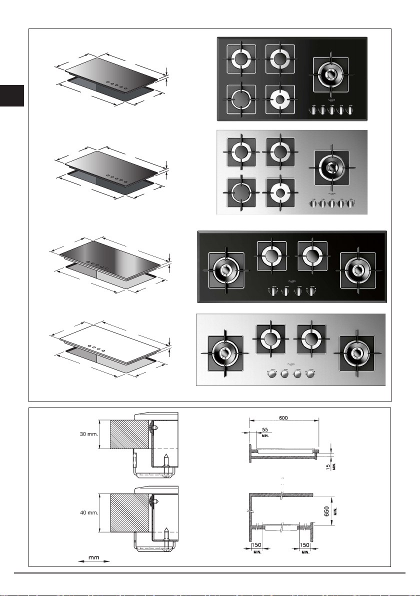
Posizionamento (Fig. 4)
L’apparecchio è previsto per essere incassato in un
piano di lavoro come illustrato nell’apposita figura.
Prima di inserire il piano predisporre la guarnizione di
tenuta su tutto il perimetro della foratura d’incasso.
Fig. 4
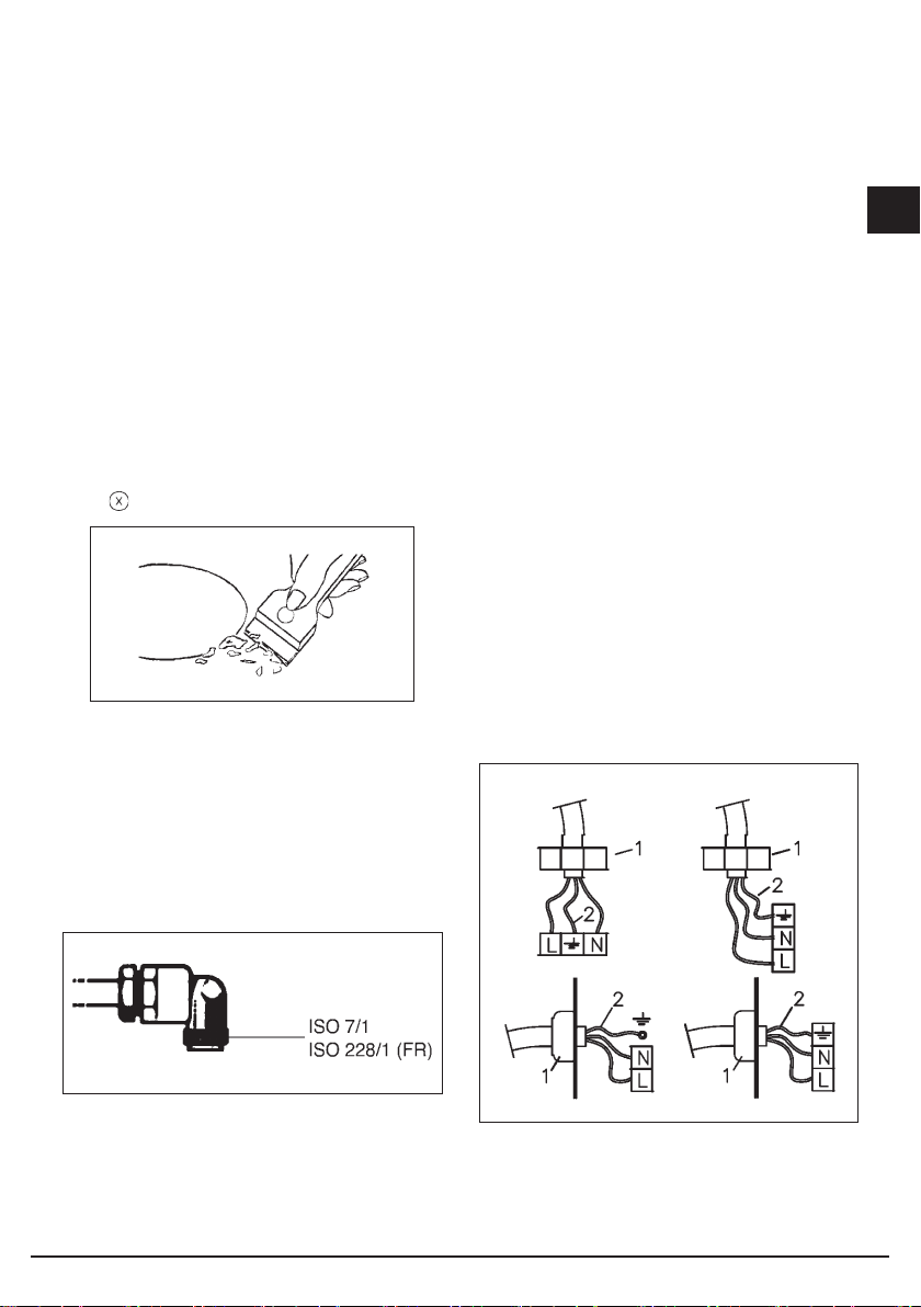
Collegamento gas (Fig. 5)
Collegare l’apparecchiatura alla bombola o all’impianto
secondo le prescrizioni delle norme in vigore
accertandosi preventivamente che l’apparecchiatura sia
predisposta al tipo di gas disponibile. In caso contrario
vedi: “Adattamento a diverso tipo di gas”. Verificare
inoltre che la pressione di alimentazione rientri nei valori
riportati nella tabella: “Caratteristiche utilizzatori”.
Fig. 5
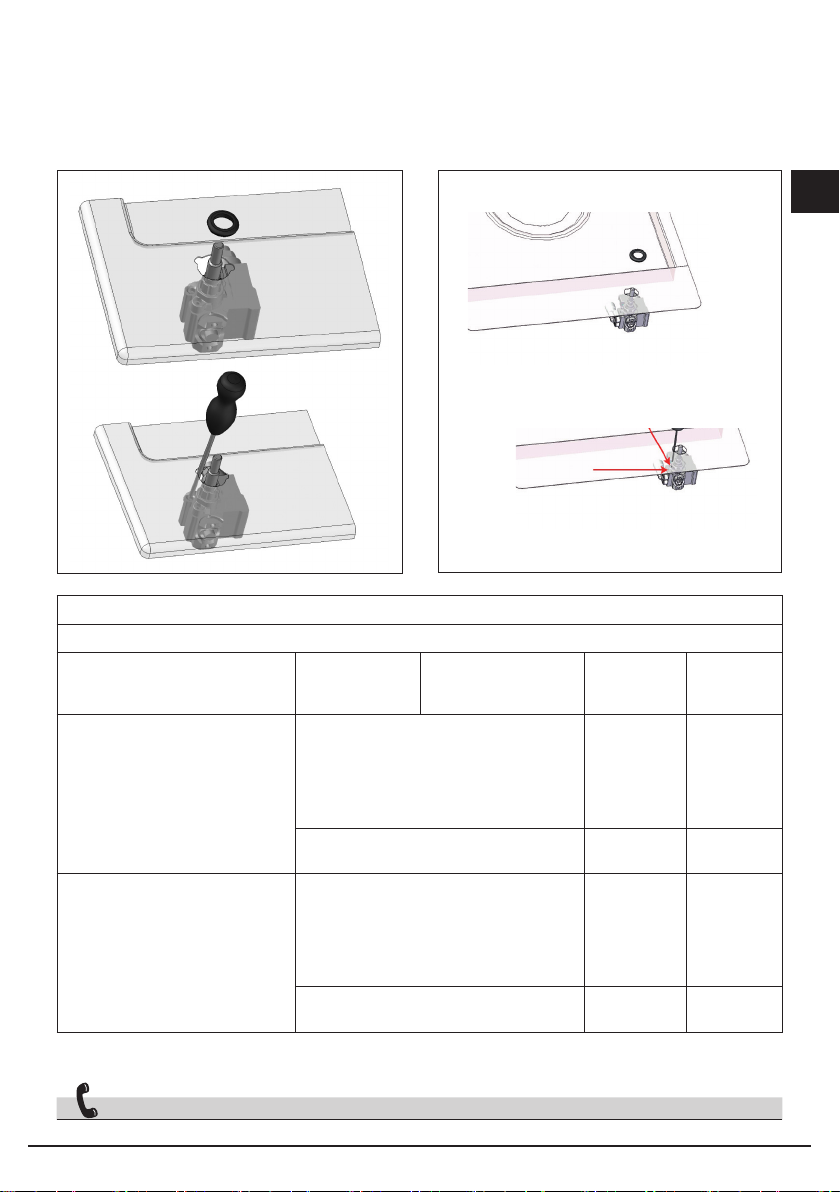
Allacciamento metallico rigido/semirigido
Eseguire l’allacciamento con raccordi e tubi metallici
(anche flessibili) in modo da non provocare sollecitazioni
agli organi interni all’apparecchio.
N.B. - Ad installazione ultimata controllare, con una
soluzione saponosa, la perfetta tenuta di tutto il sistema
di collegamento.
Collegamento elettrico (Fig. 6)
Prima di effettuare l’allacciamento elettrico accertarsi
che:
• le caratteristiche dell’impianto siano tali da soddisfare
quanto indicato sulla targa matricola applicata sul
fondo del piano;
• l’impianto sia munito di un efficace collegamento di
terra secondo le norme e le disposizioni di legge in
vigore. La messa a terra è obbligatoria a termini di
legge.
Nel caso che l’apparecchiatura non sia munita di
cavo e/o di relativa spina utilizzare materiale idoneo
per l’assorbimento indicato in targa matricola e per la
temperatura di lavoro. Il cavo in nessun punto dovrà
raggiungere una temperatura superiore di 50°C a quella
ambiente.
Per il collegamento diretto alla rete è necessario
interporre un interruttore omnipolare dimensionato per
il carico di targa che assicuri la sconnessione della rete
con una distanza di apertura dei contatti che consenta
la disconnessione completa nelle condizioni della
categoria di sovratensione III, conformemente alle
regole di installazione (il cavo di terra giallo/verde non
deve essere interrotto). La presa o l’interruttore om-
nipolare devono essere facilmente reggiungibili con
l’apparecchiatura installata.
Fig. 6
Se il cavo di alimentazione è danneggiato, esso deve
essere sostituito dal costruttore o dal suo servizio
assistenza tecnica o comunque da una persona con
qualifica similare, in modo da prevenire ogni rischio.
Istruzioni per l’installatore
1 - FERMACAVO 2 - GIALLO VERDE

8 9
I
• per la regolazione del minimo agire con opportuno
cacciavite sulla vite posta sul rubinetto (Fig. 8) dopo
averlo ruotato in posizione di minimo. Per GPL
(butano/propano) avvitare a fondo.
Adattamento a diverso tipo di gas (Fig. 7)
Se l’apparecchiatura risulta predisposta per un diverso
tipo di gas da quello di alimentazione disponibile, si deve
procedere:
• alla sostituzione dell’iniettore (Fig. 7) con i
corrispondenti al tipo di gas da utilizzate (vedi tabella
“Caratteristiche utilizzatori”);
A
B
Fig. 8
Fig. 7
solo Wok
solo MiniWok
Solo Wok Dual

8 9
I
CARATTERISCHE URTILIZZATORI
BRUCIATORI GAS
ALIMENTAZIONE
TIPO PRESSIONE mbar
NORM.
BRUCIATORE Ø INIETTORE
1/100
PORTATA
TERMICA
NOMINALE
CONSUMO
Gas naturale G20 20
rapido 129 3000 286
l/h
semirapido 101 1750 167
ausiliario 77 1000 95
Wok 150 4000 381
MiniWok 140 3500 333
Wok Dual A - Ø71 4000 381
B - Ø95
Gas liquido G30/G31 28-30/37
rapido 87 3000 218
g/h
semirapido 66 1750 127
ausiliario 50 1000 73
Wok 102 4000 291
MiniWok 93 3500 254
Wok Dual A - Ø46 4000 291
B - Ø65
SERVIZIO ASSISTENZA TECNICA: 199.151.195
Fig. 8BFig. 8A

1110
I

11
GB
10
Index
Instructionsfor use
Installation, 12
Use, 12
Maintenance, 13
Instructions for the installater
Installation, 15
Gas connection, 15
Electrical connection, 15
User characteristics, 17
THIS APPLIANCE IS CONCEIVED FOR
DOMESTIC USE ONLY.
THE MANUFACTURER SHALL NOT IN
ANY WAY BE HELD RESPONSIBLE FOR
WHATEVER INJURIES OR DAMAGES ARE
CAUSED BY INCORRECT INSTALLATION OR
BY UNSUITABLE, WRONG OR ABSURD USE.
THIS APPLIANCE IS NOT INTENDED FOR
USE BY PERSONS (INCLUDING CHILDREN)
WITH REDUCED PHYSICAL, SENSORY
OR MENTAL CAPABILITIES, OR LACK OF
EXPERIENCE AND KNOWLEDGE, UNLESS
THEY HAVE BEEN GIVEN SUPERVISION OR
INSTRUCTION CONCERNING USE OF THE
APPLIANCE BY A PERSON RESPONSIBLE
FOR THEIR SAFETY.
CHILDREN SHOULD BE SUPERVISED TO
ENSURE THAT THEY DO NOT PLAY WITH
THE APPLIANCE.
Dear customer,
We thank you and congratulate you on your
choice.
This new carefully designed product,
manufactured with the highest quality
materials, has been carefully tested to
satisfy all your cooking demands.
We would therefore request you to read
and follow these easy instructions which will
allow you to obtain excellent results right
from the start.
May we wish you all the very best with your
modern appliance!
THE MANUFACTURER
Italiano
I
GB English
FR Français
DE
ES
Deutsch
Español
PT Português

12 13
GB
Installation
All the operations concerned with the installation
(electrical and gas connections, adaptation to type of
gas, necessary adjustments, etc.) must be carried out
by qualified technicians, in terms with the standards
in force. For specific instructions, kindly read the part
reserved for the installation technician.
Use
Use Gas burners (Fig. 1-3)
The ignition of the gas burner is carried out by putting
a small flame to the upper part holes of the burner,
pressing and rotating the corresponding knob in an
anti-clockwise manner, until the maximum position has
coincided with the marker. When the gas burner has
been turned on, adjust the flame according to need.
The minimum position is found at the end of the anti-
clockwise rotation direction.
For models with automatic/ simultaneous (with one
hand) ignition, it is sufficient to proceed as described
above using the corresponding knob. The electric spark
between the ignition plug and the burner provides the
ignition of the burner itself. After ignition, immediately
release the push-button and adjust the flame according
to need. For models with a thermoelectric safety system,
the burner is ignited as in the various cases described
above, keeping the knob fully pressed on the maximum
position for approximately 3/5 seconds. After releasing
the knob, make sure the burner is actually lit.
N.B.
- We recommend the use of pots and pans with a
diameter matching that of the burner, thus preventing
the flame from escaping from the bottom part and
surrounding the pot;
- do not leave any empty pots or pans on the fire;
- do not use any tools for grill-cooking on Crystal hobs.
When cooking is finished, it is also a good norm to close
the main gas pipe tap and/or cylinder.
DWK models
Models SH 775 G DWK, SH 905 G DWK and SH 1124
G 2DWK have a Dual Wok burner. The centre flame (F1)
can be lit by pressing the knob and turning it clockwise
or the entire burner (F2) can be lit as shown in the figure
below.
Important
GAS PROTEKT
On floors with thermoelectric protection (
Gas Protekt
)
do not keep the ignite button pushed for more than 15
seconds. If the burner has not ignited after 15 seconds,
open the door of the room and wait at least one minute
before making a further attempt.
wok Ø 20-32
fast Ø 20-26
semifast Ø 14-20
auxiliary* Ø 10-14
*with reduction grid
GAS
Fig. 1
Instructions for use
F1
F2
F1
F2
F1
F2
F1
F2

12 13
GB
Maintenance Gas/Electrical
Prior to any operation, disconnect the appliance from
the electrical system. For long-life to the equipment, a
general cleaning operation must take place periodically,
bearing in mind the following:
• the glass, steel and/or enamelled parts must be
cleaned with suitable non-abrasive or corrosive
products (found on the market). Avoid chlorine-base
products (bleach, etc.);
• avoid leaving acid or alkaline substances on the
working area (vinegar, salt, lemonjuice, etc.);
• the wall baffle and the small covers (mobile parts of
the burner) must be washed frequently with boiling
water and detergent, taking care to remove every
possible encrustation. Dry carefully and check that
none of the burner holes is fully or partially clogged;
• the electrical parts are cleaned with a damp cloth and
are lightly greased with lubricating oil when still warm;
• the stainless steel grids of the working area, after
having been heated, take on a bluish tint which does
not deteriorate the quality. To bring colour back to its
original state, use as lightly abrasive product.
N.B.- Cleaning of the taps must be carried out by
qualified personnel, who must be consulted in case of
any functioning anomaly. Check periodically the state
of conservation of the flexible gas feed pipe. In case of
leakage, call immediately the qualified technicians for its
replacement.
DO NOT USE STEAM CLEANERS
510 909
490
840
53,5
55
510 620
480
560
770
55
490
510
750
Fig. 2
510 909
55
490
840
770
55
490
510
750
mod. FCH 604 G BK - FCH 604 G WH - FCH 604 G ME
mod. FCH 775 G WK BK - FCH 775 G WK WH
FCH 775 G WK ME
mod. FSH 775 G DWK XX

14 15
GB
Fig. 3
Fig. 2A
510 909
55
490
840
770
55
490
510
750
510 909
55
490
840
770
55
490
510
750
425
1120
55
405
1100
425
1120
55
405
1100
mod. FCH 905 G DWK BK - FCH 905 G DWK WH
FCH 905 G DWK ME
mod. FCH 1124 G 2DWK BK
FCH 1124 G 2DWK WH - FCH 1124 G 2DWK ME
mod. FSH 1124 G 2DWK XX
mod. FSH 905 G DWK XX

14 15
GB
Installation
This appliance is not provided with a combustion
product discharge. It is recommended that it be installed
insufficiently aerated places, in terms of the laws in force.
The quantity of air which is necessary for combustion
must not be below 2.0 m3/h for each kW of installed
power. See table of burner power.
Positioning (Fig. 4)
The appliance can be fitted into a working area
as illustrated on the corresponding figure. Before
positioning the hob, fit the seal around the entire
periphery of the hole cut in the worktop.
Fig. 4
Gas connection (Fig. 5)
Connect the appliance to the gas cylinder or to the
installation according to the prescribed standards
in force, and ensure beforehand, that the appliance
matches the type of gas available. Other wise, see
”Adaptation to various types of gas”. Further more,
check that the feed pressure fall swithin the values
described on the table: ”User chacteristics”.
Fig. 5
Rigid/semi rigid metalconnection
Carry out the connection with fittings and metal pipes
(even flexible pipes) so as to obtain counter stress the
inner parts of the appliance.
N.B. - when the installation has been carried out, check
the perfect sealing of the entire connection system, by
using a soapy solution.
Electrical connection (Fig. 6)
Prior to carrying out the electrical connection, please
ensure that:
• the plant characteristics are such as to follow what is
indicated on the matrix plate placed at the bottom of
the working area;
• that the plant is fitted with an efficient earth connection,
following the standards and law provisions in force.
The earth connectionis compulsory in terms of the
law.
Should there be no cable and/or plug on the equipment,
use suitable absorption material for the working
temperature as well, as indicated on the matrix
plate. Under no circumstance must the cable reach a
temperature above 50°C of the ambient temperature.
If connecting directly to the mains power supply, fit a
multi-pole switch of a suitable size for the rated capacity
with a clearance distance which completely disconnects
the power line under overvoltage category III conditions,
consistently with the rules of installation (the yellow/
green earth wir must not be interrupted). The plug or
omnipolar switch must be easily reached on the installed
equipment.
Fig. 6
To avoid all risk, if the power cable becomes
damaged, it must only be replaced by the
manufacturer, by an authorised service centre, or by
a qualified electrician.
Instructions for the installer
1 - CABLE-CLAMP 2 - YELLOW/GREEN

16 17
GB
Adaptation to varius types of gas (Fig. 7)
Should the appliance be pre-set for a different type of
gas than available, procreed as follows:
• replace the injector (Fig. 7) with the corresponding type
of gas to be used (see table “User characteristics“);
• to adjust to the minimum, use a screwdriver on the
screw placed on the tap (Fig. 8) after turning the tap
to its minimum position.
For GPL (butane/propane) screw tight.
A
B
Fig. 7
Fig. 8
solo Wok
solo MiniWok
Solo Wok Dual

16 17
GB
Fig. 8BFig. 8A
USER CHARACTERISTICS
GAS BURNERS
FEED
TYPE PRESSURE mbar
NORM.
BURNER Ø INJECTORS
1/100
THERMAL
CAPACITY
CONSUMPTION
Natural gas G20 20
fast 129 3000 286
l/h
semifast 101 1750 167
auxiliary 77 1000 95
Wok 150 4000 381
MiniWok 140 3500 333
Wok Dual A - Ø71 4000 381
B - Ø95
Liquefied
gas G30/G31 28-30/37
fast 87 3000 218
g/h
semifast 66 1750 127
auxiliary 50 1000 73
Wok 102 4000 291
MiniWok 93 3500 254
Wok Dual A - Ø46 4000 291
B - Ø65

1918
GB

19
FR
18
Index
Notice d’emploi
Installation, 20
Mode d’emploi, 20
Entretien, 21
Modalités d’installation
Installation, 23
Connexion gaz, 23
Branchement électrique, 23
Caractéristiques utilisateurs, 25
CE PRODUIT EST CONÇU EXCLUSIVEMENT
POUR USAGE DOMESTIQUE.
LE CONSTRUCTEUR DÉCLINE TOUTE
RESPONSABILITÉ POUR DOMMAGES
ET BLESSURES CAUSÉES PAR UNE
INSTALLATION INCORRECTE OU PAR UN
USAGE IMPROPRE, ERRONÉ OU ABSURDE.
L’APPAREIL NE DOIT PAS ÊTRE UTILISÉ
PAR DES PERSONNES (ENFANTS INCLUS)
DISPOSANT DE CAPACITÉS PHYSIQUES,
SENSORIELLES OU MENTALES RÉDUITES,
OU PAR DES PERSONNES N’AYANT PAS
L’EXPÉRIENCE OU LES CONNAISSANCES
REQUISES, SI CE N’EST SOUS LA
SURVEILLANCE D’UNE PERSONNE
RESPONSABLE DE LEUR SÉCURITÉ OU
APRÈS AVOIR REÇU DE CELLE-CI LES
INSTRUCTIONS RELATIVES À L’UTILISATION
DE L’APPAREIL. LES ENfANTS DOIVENT
ÊTRE SURVEILLÉS, AFIN DE S’ASSURER
QU’ILS NE JOUENT PAS AVEC L’APPAREIL.
Chère cliente,
merci et sincères félicitations pour le choix
que vous avez fait.
Ce nouveau produit, développé avec soin et
fabriqué avec des matières de toute première
qualité, a été soigneusement rodé pour
satisfaire toutes Vos exigences d’une cuisson
parfaite.
Veuillez lire attentivement les instructions
simples portées sur cette notice qui vous
permettront d’obtenir d’excellents résultats
dès la première utilisation. Nous vous
souhaitons une entière et pleine satisfaction
quant à l’utilisation de cet appareil moderne.
E CONSTRUCTEUR
Italiano
I
GB English
FR Français
DE
ES
Deutsch
Español
PT Português

20 21
FR
Installation
Toutes les opérations relatives à l’installation
(branchement électrique, raccordement gaz, adaptation
au type de gaz, réglages nécessaires, etc...) doivent être
effectuées par des spécialistes suivant les normes en
vigueur. Pour les instructions spécifiques, voir la partie
qui concerne les modalités d’installation.
Mode d’emploi
Brûleurs à gaz (Fig. 1-3)
On allume le brûleur en approchant une petite flamme
aux trous de sa partie supérieure en poussant et tournant
dans le sens contraire des aiguilles d’une montre la
manette correspondant jusqu’à faire coïncider l’aiguille
avec la position de maximum. Quand le bruleur est en
marche, règler la flamme selon la nécéssité. La position
de minimum se trouve à la fin de la rotation contraire au
sens des aiguilles d’une montre.
Pour les modèles à allumage automatique/simultané (à
une main), il suffit d’agir sur le bouton correspondant,
comme il est indiqué ci-dessus. La décharge électrique
entre la petite bougie et le brûleur allume le brûleur
interessé.
Quand le brûleur est allumé, lâcher la manette, et
regler la flamme selon nécéssité. Dans le cas de
modèles doués de sûreté thermoélectrique, l’allumage
du brûleur a lieu comme dans les cas décrits ci-dessus
en appuyant à fond sur la manette placée à la position
maximale pendant environ 3/5 secondes. Au moment où
vous relâchez la manette, assurez-vous que le brûleur
est allumé.
N.B.:
- On Vous conseille d’utiliser des casseroles avec un
diamètre proportionné aux brûleurs évitant que la
flamme au maximum déborde de leur fond;
- ne laissez jamais de casseroles vides sur le feu
allumé;
- n’employez pas d’ustensiles pour cuisson grill sur les
plaques dessus verre.
A la fin de la cuisson il faut fermer le robinet principal du
conduit et/ou de la bouteille.
Modèles DWK
Les modèles SH 775 G DWK, SH 905 G DWK et SH
1124 G 2DWK sont équipés d’un brûleur Dual Wok. Il est
possible d’allumer la flamme centrale (F1) en tournant et
en pressant la bouton dans le sens horaire, ou allumer
tout le brûleur (F1) de la façon indiquée sur la figure ci-
dessous.
Importante
GAS PROTEKT
Sur les plaques dotées de sécurité thermoélectrique
(
Gas Protekt
), ne pas activer l’allumage pendant plus de
15 secondes.
Si , après 15 secondes le brûleur ne s’est pas allumé,
ouvrir la porte de la pièce et attendre au moins une
minute avant de réessayer.
wok Ø 20-32
rapide Ø 20-26
semirapide Ø 14-20
auxiliaire* Ø 10-14
*avec grille de réduction
GAZ
Fig. 1
Notice d’emploi
F1
F2
F1
F2
F1
F2
F1
F2
This manual suits for next models
6
Table of contents
Languages:
Other FULGOR Hob manuals