Fuling Inverter DZB100 Series User manual

220Vseries220Vseries
: :
0.5~3.7KW0.5~3.7KW
400Vseries: 0.5~400KW400Vseries: 0.5~400KW
660Vseries: 15~630KW660Vseries: 15~630KW
1140Vseries: 55~630KW1140Vseries: 55~630KW

TT
ABLE ABLE
OF CONTENTOF CONTENT
SS
Chapter 1 IntroductionChapter 1 Introduction
Chapter 2 Installation and WiringChapter 2 Installation and Wiring
Chapter 3 Digital Keypad OperationChapter 3 Digital Keypad Operation
Chapter 4 Start UpChapter 4 Start Up
Chapter 5 Summary of Parameter SettingsChapter 5 Summary of Parameter Settings
Chapter 6 Parameter SettingsChapter 6 Parameter Settings
Chapter 7 TChapter 7 T
roubleshooting and Fault roubleshooting and Fault
informationinformation
AppendiAppendi
xx
AA
StandaStanda
rd rd
SpecifiSpecifi
cationcation
ss
Appendix B Serial CommunicationsAppendix B Serial Communications
Appendix C DimensionsAppendix C Dimensions
AppendiAppendi
x Dx D
AccessoAccesso
ries Listries List
Chapter 8 Quality GuaranteeChapter 8 Quality Guarantee
PrefacePreface

-1-1
--
PrefacePreface
DD
ZZ
BB
11
00
0 0
DD
ZZ
BB
11
00
00
TT
hh
aa
nn
k k
yy
oo
u u
ff
oo
r r
cc
hh
oo
oo
ss
ii
nn
g g
hh
ii
gg
hh
--
pp
ee
rr
ff
oo
rr
mm
aa
nn
cc
e A C e A C
MM
oo
tt
oo
r r
DD
rr
ii
vv
ee
ss
. .
SS
ee
rr
ii
ee
s s
aa
rr
ee
manufactured by adopting high-quality components, material and incorporating the latestmanufactured by adopting high-quality components, material and incorporating the latest
microprocessor technology available.microprocessor technology available.
Getting StartedGetting Started
This manual will be helpful in the installation, parameter setting, troubleshooting, and dailyThis manual will be helpful in the installation, parameter setting, troubleshooting, and daily
maintenance of themaintenance of the
AC motor drives. TAC motor drives. T
o guarantee safe operation of the equipment, reado guarantee safe operation of the equipment, read
the following safety guidelines before connecting power to thethe following safety guidelines before connecting power to the
AC drives. Keep AC drives. Keep
thisthis
operating manual handy and distribute to all users for reference.operating manual handy and distribute to all users for reference.
SeriesSeries
AA
TT
TT
EE
NN
TT
II
OO
NN
: :
DD
ZZ
BB
11
00
00
DANGER!DANGER!
WARNING!WARNING!
WARNING!WARNING!
AA
TT
TT
EE
NN
TT
II
OO
NN
: :
cc
oo
nn
nn
ee
cc
tt
ii
nn
g g
tt
hh
e e
EE
aa
rr
tt
h h
GG
rr
oo
uu
nn
d d
tt
o o
tt
hh
ee
drive ground terminaldrive ground terminal
CAUTION:CAUTION:
TT
o avoid damage to o avoid damage to
the drivethe drive
CAUTION:CAUTION:
this will damage the drivethis will damage the drive
CAUTION:CAUTION:
AlAl
wawa
ys ys
rere
ad ad
thth
is is
manman
ual ual
thotho
roro
ugug
hly hly
befbef
oror
e e
usus
inin
g g
sese
riri
eses
AC AC
MoMo
toto
r r
DrDr
iveive
s.s.
AC input power must be disconnected before any maintenance.AC input power must be disconnected before any maintenance.
Do not connect or disconnect wires and connectors while power is applied to the circuit.Do not connect or disconnect wires and connectors while power is applied to the circuit.
Maintenance must be performed by qualified technicians.Maintenance must be performed by qualified technicians.
TT
o avoid personal injury, do not ro avoid personal injury, do not r
emove the cover of theemove the cover of the
AC motor drive until all ofAC motor drive until all of
thedigital keypad thedigital keypad
"DISPLA"DISPLA
Y LED" lamps are off. The DC-link capacitor Y LED" lamps are off. The DC-link capacitor
remainsremains
charged with a hazardous voltage even after input power is removed.charged with a hazardous voltage even after input power is removed.
Grounding the DZB100B drive is done byGrounding the DZB100B drive is done by
..
There are highly sensitive components on the printed circuit boards. These componentsThere are highly sensitive components on the printed circuit boards. These components
aa
rr
e e
ee
ss
pp
ee
cc
ii
aa
ll
ll
y y
ss
ee
nn
ss
ii
tt
ii
vv
e e
tt
o o
EE
SS
D D
((
ee
ll
ee
cc
tt
rr
oo
ss
tt
aa
tt
ii
c c
dd
ii
ss
cc
hh
aa
rr
gg
ee
))
. .
,,
do not touch components or the circuit boards until static control precautions have beendo not touch components or the circuit boards until static control precautions have been
taken.taken.
NeNe
veve
r cr c
onon
nene
ct ct
thth
e e
mama
in in
cici
rcrc
uiui
t t
ouou
tptp
ut ut
tete
rmrm
inin
alal
s Us U
, V, an, V, an
d W d W
didi
rere
ctct
ly ly
to to
thth
ee
AC AC
mama
inin
cc
ii
rr
cc
uu
ii
t t
pp
oo
ww
ee
r r
ss
uu
pp
pp
ll
y y
aa
s s
..
Do not apply the antirust to screws for fastenDo not apply the antirust to screws for fasten
ing drives; Please clean the ing drives; Please clean the
drives anddrives and
screws with dry cloth or alcohol, not with synthetscrews with dry cloth or alcohol, not with synthet
ic cleaner. Fasten the screws withic cleaner. Fasten the screws with
washers and rated torque lest the enclosure corners of drives be distorted.washers and rated torque lest the enclosure corners of drives be distorted.
This manual is This manual is
for DZB100 Seriesfor DZB100 Series
AC Motor AC Motor
Drive.Drive.
PrefacPrefac
ee
DZB1DZB1
00 00
SeriSeri
eses
!!
WARNING WARNING

-2-2
--
1.1 Receiving, Storage and Transportation1.1 Receiving, Storage and Transportation
InIn
trtr
odod
ucuc
titi
onon
Chapter 1 IntroductionChapter 1 Introduction
DZB1DZB1
00 00
SeriSeri
eses
ThTh
e e
pupu
rprp
osos
e e
of of
thth
is is
chch
apap
tete
r r
is is
to to
prpr
ovov
idid
e e
spsp
ecec
ifif
icic
, ,
yeye
t t
sisi
mpmp
le le
inin
fofo
rmrm
atat
ioio
n n
to to
, ,
thth
ee
AC drive. This chapter contains information on the AC drive. This chapter contains information on the
following:following:
unpack installunpack install
1.1 Receiving, Transportation, and Storage1.1 Receiving, Transportation, and Storage
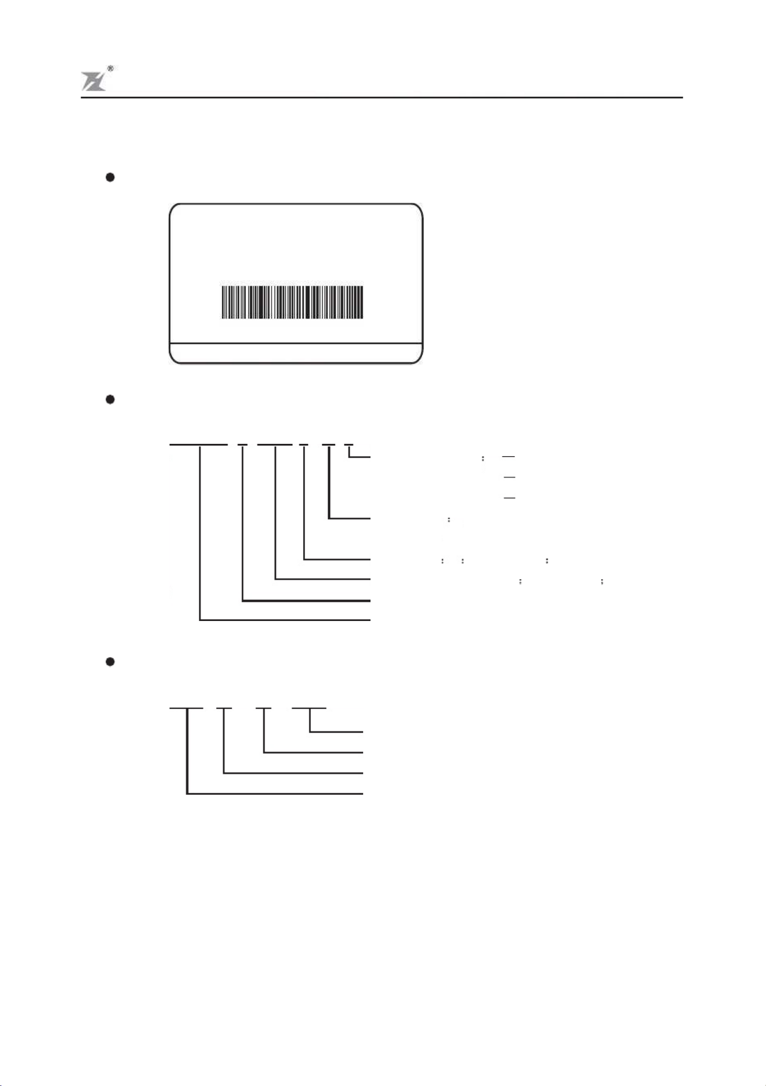
1.2 Nameplate Information1.2 Nameplate Information
TheThe
AC motor drive has gone through rigorous quality control tests at the factory before shipment.AC motor drive has gone through rigorous quality control tests at the factory before shipment.
After receiving theAfter receiving the
AC drive, check for AC drive, check for
the following.the following.
ReceivingReceiving
1.Check to make sure that the 1.Check to make sure that the
package includes anpackage includes an
AC drive,the User AC drive,the User
Manual,dust covers andManual,dust covers and
rubber bushings.rubber bushings.
2.Inspect the unit to insure it was not damaged during shipment.2.Inspect the unit to insure it was not damaged during shipment.
3.Make sure that the part number indicated on the nameplate corresponds with the part number3.Make sure that the part number indicated on the nameplate corresponds with the part number
of your oof your o
rder.rder.
StorageStorage
TheThe
AC Drive should be kept in the shipping carton before installation. In order to retain theAC Drive should be kept in the shipping carton before installation. In order to retain the
warranty coverage, thewarranty coverage, the
AC drive should be AC drive should be
stored properly stored properly
when it is not when it is not
to be used for anto be used for an
extended period of time. Some storage suggestions are:extended period of time. Some storage suggestions are:
1.Store in a clean, dry location.1.Store in a clean, dry location.
2.Stor2.Stor
e e
within within
an an
ambient ambient
temperatempera
ture ture
range range
of of
-20 -20
C C
to to
+65 +65
C.C.
3.If possible, store in 3.If possible, store in
an air-conditioned environment where the relative humidity an air-conditioned environment where the relative humidity
is less thanis less than
95%, non-condensing.95%, non-condensing.
4.Do not store the4.Do not store the
AC drive in places where it could be exposed to corrosive gases.AC drive in places where it could be exposed to corrosive gases.
5.Do not store the5.Do not store the
AC drive on a shelf or on an unstable surface.AC drive on a shelf or on an unstable surface.
TransportationTransportation
TT
emperatuemperatu
re: re:
-25 -25
C C
to to
+70 +70
C; C;
R.H.R.H.
: :
0% 0%
to to
95%;95%;
Air Pressure: 70kPa to 106kPa.Air Pressure: 70kPa to 106kPa.

-3
-
1.2 Nameplate Information
Description of Serial Number:
Description of
AC Motor
Drive Model:
DZB 100
B
0 0 7 5
L
4
A
Func
tion
leve
l
code
A
brak
ing
unit
insid
e
B
non
brak
ing
unit
C
spe
ci
al
mod
el
2-2
20V
4-4
00V
6-660V 11-1400V
L
0-
40
0.
0H
z H
0015
:1.5
KW
0075
:7.5
KW
Input voltage
Freq. Range
Applicable motor capacity
Series name
B Series
0-2000Hz
In
tr
od
uc
ti
on
Example:
DZB1
00
Seri
es
MODEL:DZB100B0075L4A
T
AIZHOU
FULING
ELECTROM
OTOR
CO.,L
TD.
S / N : F L 7 5 / 0 5 0 5 8 8 8 8
INP
UT
:
3P
H 38
0V 5
0/
60
Hz
OUTPUT
: 3P
H
0~380V
0~400H
z
POWER: 7.5KW 18.0A
0 0 0 1
0
5
0
5
F L 7 5
Production number
Production month
Production year
Model
Name:FL7
5-7
Model
5

-4
-
Description of Serial Name:
In
tr
od
uc
ti
on
DZB1
00
Seri
es
S
e
r
i
e
s
C
o
d
e
E
x
p
l
a
n
a
t
i
o
n
A
p
p
l
i
c
a
b
l
e
M
o
t
o
r
2.2~30KW
(3.0~40KVA)
B Series
P Series
S Series
H Series
D Series
M Series
L Series
T Series
PP Series
0.55~400KW
7.5~400KW
7.5~280KW
15~220KVA
0.55~2.2KW
0.55~75KW
0.55~2.2KW
3.7~400KW
High-Perfo
rmance General-Purpose AC
Motor Drives
Specific AC Motor Drives For Fan&Pump
Specific AC
Motor Drives For
Plastic Molding
Machinery
Specific AC Motor Drives For High-Speed Motor
Specific AC Motor Dri
ves For V
ariable Power
High-Perfo
rmance Micro-TypeAC Motor
Drives
Specific AC Motor Drives For Bobbin Machinery
Specific AC Motor Drives For The Gating Of Elevator
Specific AC Motor Drives For Isob
arically Water Supply

-5
-
2.1 Installation Requirements
In
st
al
la
ti
on
an
d Wi
ri
ng
Chapter 2 Installation and Wiring
DZB1
00
Seri
es
Ch
ap
te
r
2
pr
ov
id
es
th
e
in
fo
rm
at
io
n
ne
ed
ed
to
pr
op
er
ly
an
d
th
e
AC
dr
iv
e.
Make sure that the
AC drive is wired according to the instructions contained in this chapter.
The instructions should be read and understood before the actual installation begins.
i
n
s
t
a
l
l
w
i
r
e
2.1 Installation Requirements
2.2 Wiring
2.3 Basic Wiring Diagram
Install the
AC drive
vertically to provide
proper ventilation.
Adequate space isrequired
between
the drive and a wall
or other equipment. The figure
below shows
the minimum space needed.
All enclosures must pr
ovide adequate ventilation and
the internal ambient
temperature
must
be
kep
t
at
40
or
belo
w
.
A
I
R
A
I
R
RUN
STOP
JOG
FWD
REV
PRGM
RESET
DATA
FUNC
1.protected from rain or moisture;
2.protected from direct sunlight;
3.protected from corrosive gases or liquids;
4.free from airborne dust or metallic particles;
5.free from vibration;
6.free from magnetic noise
7.tempe
rature:
-10
C
to
+40
C;
R.H.
: 0
%
to
90%;
air
pressu
re:
86kPa
to
106
kPa
Wiring orifice
Caution:
The
AC drive should be installed
in an environment that is:

-6
-
2.2 Wiring
Main Cir
cuit
Wiri
ng
Power input and output may be connected via a nine or ten position termina block. The pin
assignments are as follows:
Model
Power
terminal
pin
assignments
In
st
al
la
ti
on
an
d Wi
ri
ng
DZB1
00
Ser
ies
(1) Power terminal block designations
Applicable motor
capacity
9
3
~
1
3
2
K
W
(
3
8
0
V
)
Series
0.
55
KW
(2
20
V
Se
ri
es
)
~0.75
1
.
5
K
W
(
2
2
0
V
)
Series
0.75~2.2KW(380V Series)
0
.
7
5
~
1
.
5
K
W
(
2
2
0
V
)
Series
0.75~1.5KW(380V Series)
2.2~3.7KW(220VGrade)
2.2~5.5KW (380V Series)
7.5~15KW(380V Series)
1
8
.
5
~
3
0
K
W
(
3
8
0
V
)
Series
132~160KW(380V Series)
3
7
~
4
5
K
W
(
3
8
0
V
)
Series
55~75KW(380V Series)
Earth
Ground
AC Input Line
Terminals
BR+ BR-
Breaking
Resistor
Motor
Connection
U
V
W
R
T
S
R
E
Earth
Ground
AC Input Line
Terminals
BR+
BR
-
Breaking
Resistor
Motor
Connection
U
V
W
T
S
Earth
Ground
AC Input Line
Terminals
R
T
S
B
R
+
B
R
-
Breaking
Resistor
Motor
Connection
U
V
W
R
E
Earth
Ground
AC Input Line
Terminals
BR+ BR-
Breaking
Resistor
Motor
Connection
U
V
W
T
S
R
S
T
U
V
W
AC Input Line
Terminals
Earth
Ground
Motor
Connection
DC+ DC-
U
V
W
T
S
R
E
AC Input Line
Terminals
Earth
Ground
Motor
Connection
Breaking
Unit
AC Input Line
Terminals
Earth
Ground
Motor
Connection
Breaking
Unit
P
1
P
2
DC
-
U
V
W
R
S
T
1
8
7
~
2
8
0
K
W
(
3
8
0
V
)
Series
FL08
FL22
FL28
FL37
FL75
FL015
FL030
FL045
FL075
FL132
FL160
FL220

-7
-
(2) Power block terminal designations
Terminals
R
S
T
(
L
N
)
U
V
W
BR+
( D C
+ )
BR-
P 1 (
D C +
)
D C
-
P
1
P
2
Description
AC input line terminals
Motor connection
Connection for the regenerative resistor (option)
Connection for the braking unit (option)
C
o
n
n
e
c
t
i
o
n
f
o
r
t
h
e
(
o
p
t
i
o
n
)
DC Link Reactor
Gro und
In
st
al
la
ti
on
an
d Wi
ri
ng
DZB1
00
Seri
es
(3)
Attent
ion:
1.The user must provide a circuit breaker or disconnect switch and fuses in accordance with all
applicable electrical codes.
2.Make sure that the leads are
connected correctly and the
AC drive is
properly grounded.
(Ground leads should be at least th
e same size wire as the input lea
ds R, S, and T
.)
3.Use ground leads that comply with
A
WG standards. Make the length of these ground leads as
short as possible.
4.Should several
AC drive units be installed side by side, all the units should be grounded directly
to the ground poles. Do not form a loo
p with the ground leads.
5.Make sure that the power source supplies the correct voltage and is capable of supplying the
r
e
q
u
i
r
e
d
c
u
r
r
e
n
t
t
o
t
h
e A C
d
r
i
v
e
.
R
e
f
e
r
t
o
s
p
e
c
i
f
i
c
a
t
i
o
n
f
o
r
.
M
o
t
o
r
V
oltage should mat
ch the line
voltage.
6.For single phase applications, the
AC input line can be connected to any two of the three input
terminals R, S, T
.
A
single phase DZB100B drive can be powered from three phase as well as
single phase.
This drive is not intended for use with singl
e-phase motors.
7.When the
AC drive output termina
ls U, V
, and W are connected
to the motor
terminals U, V
, and
W
, respectively, the motor will rotate
counter-clockwise (viewed from th
e shaft of the
motor as
shown below) if a forward operation command is e
ntered (FWD lamp is ON).
Rated
AC Input P
ower
Note:

-8
-
In
st
al
la
ti
on
an
d Wi
ri
ng
DZB1
00
Seri
es
8.T
o reverse the direction of rota
tion, interchange any two
connections of the three mot
or leads.
9.The control lines
and power line
s (R,S,T;U,V
,W;P
,N,BR+,BR-) should be separated a
nd avoid
pa
ra
ll
el
wi
ri
ng
le
st
it
sh
ou
ld
ge
ne
ra
te
no
is
e
an
d
ca
us
e
mi
s-
op
er
at
io
n.
Do not attach or remove wiring or
connectors when power is applied to the
AC drive.
Do not monitor the signals at any point on the circuit board while the
AC drive is in
operation.
Do not connect the
AC input to any of the U, V
, W
terminals, as this will damage the
AC
drive.
Caution:
Caution:
Caution:

-9
-
In
st
al
la
ti
on
an
d Wi
ri
ng
DZB1
00
Seri
es
(2) Control terminal block descriptions
Note:
Use twisted-shielded or twisted-pair shielded-lead wires for the control signal.
It is recommended to run signal wiring in a separate steel conduit.
The shield wire should only be connected at the drive.
The control leads must be routed separately from the power supply and motor leads.
They must not be fed through the same cable conduit.
Control Circuit Wiring
T
erminal
Symbol
A
B
C
D
C
M
REV
FWD
RST
EF
TRG
DFM
D
C
M
M
C
M
V
I
F
M
SG +
SG -
EV
ACM
MO
1
MO
2
1
0
V
C
I
1
M
2
M
3
M
S
G
1
2
A
B
C
1
0
V
V
I C
I
F
M
A
C
M
M
O
M
O
M
C M
E V
F
W
D
R
E
V
D
C
M
R
S
T
E
F
T
R
G
D
C
M
D
F
M
S
G
+
2
3
1
S
G
-
M
M
M
(1) Control terminal block designations
Terminals Use
Close Contacts
Terminals
Function
"O
pe
n"
st
op
,"
Cl
os
e"
Re
ve
rs
e
"O
pen
"
sto
p,
"Cl
ose
"
For
war
d
Refer to Chapter 5, F1-57
Refer to Chapter 5,
F1-39, 40, 41, 42
Digital frequency output (0, +10 V)
"Open"
"Close":(counter
value)+1
Refer to F1-45, 46
(open collector output)
+10 V (20 mA
max. output current)
0~10 V (Max. output freq.) input
4~20 mA
(Max. output freq
.) input
0 ~10 V (Max. output freq.) output
RS-485 serial port
DC 20V ~ 24V
(50mA
Max.)
"C
lo
se
"
Re
se
t
RST-DCM
A-
B
B-
C
REV-DCM
FWD-DCM
MI
(
4
EF
)
-DCM
DFM-DCM
TRG-DCM
MO -MCM
1
MO -MCM
2
10V-ACM
VI-ACM
CI-ACM
FM-ACM
SG+-SG-
EV-DCM
MI -DCM
1
MI -DCM
2
MI -DCM
3
Reset
Multi-function
indication
output co
ntact
Multi-function input 1
Multi-function input 2
Multi-function input 3
Reverse / Stop
Forward / Stop
Digital frequency meter
Counter trigger input
Multi-function
PHC
output
1
Multi-function
PHC
output
2
Power sup
ply for
speed settin
g
Analog voltage input
Analog current input
Analog frequency/current meter
Serial communication interface
Auxiliary
control p
ower
source
Multi-function input 4
Multi-function
indication
output co
ntact

-10-
In
st
al
la
ti
on
an
d Wi
ri
ng
DZB1
00
Ser
ies
Users must connect wires according to the fo
llowing circuit diagram shown below. Do not plug a
Modem or telephone line to the RS-485 communication port, permanent damage may result.
T
erminals 1 & 2 are the power sourc
es only for the optional copy
keypad and should not be
used
while using RS-485 communication.
2.3 Basic Wiring Diagram
Braking resistior(option)
R
S
T
EV
B
R
+
B
R
-
U
V
W
E
SG+
SG-
M0
1
M0
2
MCM
ACM
+
-
FM
M
I
1
M
I
2
M
I
3
REV
FWD
RST
TRG
DFM
DCM
10V
VI
C
I
ACM
M
1
3
2
0.7
5KW
5.5
KW
8888
DCM
(
EF
)
M
I
4
A
C
B
I
MCU
WR
V
VCC
Panel Resistor
Power source
3 phase
200-240V or
380-480V
50/60Hz
R
S
T
Use a disconnect
and fuse
Frequency setting
0~10VDC
Vr:3k~5k
RS-485 Serial interface
Signal+
Multi-function PHC output
48V 50mAbelow
Analog frequency/
current meter
DC0-10V
Multi-function indication
output contact
Multi-function input 1
Multi-function input 2
Multi-function input 3
REV/STOP(REV/STOP)
FWD/STOP(RUN/STOP)
Counter trigger input
Digital signal common
Grounding
shows main circuit
shows
control
circuit
DC 20V ~ 24V
( 50mA
Max. )
Digital frequency meter
Reset
Multi-function input 4
(
External fault)
Signal-
AC 250V 2Abelow
DC 30V 2Abelow
Current input
4~20mA
+
-

-11-
In
st
al
la
ti
on
an
d Wi
ri
ng
DZB1
00
Seri
es
SG+
SG-
MCM
DFM
8888
DCM
R
S
T
EV
U
V
W
E
M0
1
M0
2
ACM
FM
M
I
1
M
I
2
M
I
3
REV
FWD
RST
TRG
DCM
10V
V
I
C
I
ACM
M
1
3
2
7.
5KW
132
KW
V
MCU
VCC
WR
Panel Resistor
V
I
C
I
S
2
Frequency setting
0~10V
A
C
B
(
EF
)
M
I
4
P1
DC-
Braking unit (option)
P2
DCLinkReactor(option)
Braking resistior
I
I
I
Frequency setting
4~20mA
S
1
Power source
3 phase
200-240V or
380-480V
50/60Hz
R
S
T
Use a disconnect
and fuse
Frequency setting
0~10VDC
Vr:3k~5k
RS-485 Serial interface
Signal+
Multi-function PHC output
48V 50mAbelow
Analog frequency/
current meter
DC0-10V
Multi-function indication
output contact
Multi-function input 1
Multi-function input 2
Multi-function input 3
REV/STOP(REV/STOP)
FWD/STOP(RUN/STOP)
Counter trigger input
Digital signal common
Grounding
shows main circuit
shows
control
circuit
DC 20V ~ 24V
( 50mA
Max. )
Digital frequency meter
Reset
Multi-function input 4
(
External fault)
Signal-
AC 250V 2Abelow
DC 30V 2Abelow
Current input
4~20mA
+
-

-12-
In
st
al
la
ti
on
an
d Wi
ri
ng
DZB1
00
Ser
ies
Notes :
Refer to F1-39, 40, 41 on page 45
.
Refer to F1-38 on page 44.
Refer to F1-45, 46 on page 48 a
nd F1-63, 64, 66 on pages 55 and
56.
Refer to F1-43 on page 47.
Refer to F1-00 on page 28, F1-48, 49
, 50 on page 49.
Refer to F1-42, 44 on pages 46 an
d 47.
Refer to F1-57 on page 53.
Refer to F1-45, 46 on page 48.
Re
fe
r
to
F1
-0
0,
01
on
pag
e
28
,
F1
-7
7,
78
on
pag
e
60
.
and 61
132
KW
315
KW
SG+
SG-
MCM
DFM
8888
DCM
R
S
T
EV
U
V
W
E
M0
1
M0
2
ACM
FM
M
I
1
M
I
2
M
I
3
REV
FWD
RST
TRG
DCM
10V
V
I
C
I
ACM
M
1
3
2
V
I
S
1
MCU
VCC
WR
Panel Resistor
V
I
C
I
S
2
Frequency setting
4~20mA
Frequency setting
0~10V
A
C
B
(
EF
)
M
I
4
Power source
3 phase
200-240V or
380-480V
50/60Hz
R
S
T
Use a disconnect
and fuse
Frequency setting
0~10VDC
Vr:3k~5k
RS-485 Serial interface
Signal+
Multi-function PHC output
48V 50mAbelow
Analog frequency/
current meter
DC0-10V
Multi-function indication
output contact
Multi-function input 1
Multi-function input 2
Multi-function input 3
REV/STOP(REV/STOP)
FWD/STOP(RUN/STOP)
Counter trigger input
Digital signal common
Grounding
shows main circuit
shows
control
circuit
DC 20V ~ 24V (
50mA
Max. )
Digital frequency meter
Reset
Multi-function input 4
(
External fault)
Signal-
AC 250V 2Abelow
DC 30V 2Abelow
Current input
4~20mA
+
-

-13-
FUNC
DATA
PRGM
RESET
FWD
REV
JOG
RUN
STOP
FWD
REV
RUN
STOP
JOG
Digital Operator
Di
gi
ta
l K
ey
pa
d O
pe
ra
ti
on
DZB1
00
Seri
es
Chapter 3 Digital Keypad Operation
Chapter 3 describes the various controls and indicators found on the digital keypad of the DZB100
AC drive. The information in this chapter should be read and understood before performing the
start-up procedures described in Chapter 4.
3.1 Description of the Digital Keypad
3.2 Explanation of Screen Display
3.3 Digital Keypad Operating Modes & Programming steps
3.1 Description of the Digital Keypad
Digital Keypad Parts and Functions
Jog key
While pressing this key, jog
speed is available.
Run key
Starts inverter drive
operation.
LED display
Indicates frequency, motor current
and alarm contents.
Up and down keys
Sets the parameter number or changes
the numerical data such as the
frequency reference.
Program / Reset key
Selects normal mode / program mode.
Displays the motor drive status, such
as output freq., selects the
par
ame
ter
s,
FWD
/RE
V or
out
put
current, etc.
Function / Data key
Displays the motor drive status, such as frequency
reference, output frequency or output current under
the normal mode; or sets parameters under the
pro
gra
m m
ode
.
Stop key
StopsAC
Motor Drive operation.
Forward / Reverse key
Selects FWD or REV operation.
LED indication
Red lamp lights during RUN,
STOP
, JOG, FWD,
or
REV operation.
This digital keypad module includes two parts: display panel and a keypad. The display panel
allows the user to program the
AC drive, as well as view the dif
ferent operating parameters. The
keypad is the user interface to the
AC motor drive. Refer to the following figure for a description
of the different parts.

-14-
Di
gi
ta
l K
ey
pa
d O
pe
ra
ti
on
DZB1
00
Ser
ies
Note:
Pressing the "Up" or "Down" button momentarily changes the parameter settings in
increments. Press and hold down either
of these keys to rapidly run through
the possible
settings.
STOP
Stop
Used to s
top the
AC drive operation.
Up / Down
Press the "Up" or "Down" button to change parameter settings.
These keys may also be used to scroll through different operating values or
pa
ra
me
te
rs
.
FW
D
RE
V
Forward / Reverse
Used to toggle between forward and reverse operation.
Pressing this key will cause the motor t
o ramp down to 0 Hz and then ramp up
to the preset speed in the opposite direction. By default, the digital keypad
controls the
AC drive
forward/reverse operation.
T
o control the forward/reverse operati
on via the control terminal
block,
ch
an
ge
th
e
F1
-0
1
pa
ra
me
te
r
to
00
01
or
00
02
.
JOG
RUN
Jo
g
Used to start the
AC drive, then run at the jog frequency as set by the parameter
specified under F1-23 [Jog Frequency].
Program / Reset
Used to select the Normal mode of operation or to program the
AC drive when
either the drive is running or h
as stopped. Switch to the PRGM mode to select
a parameter or change the setting of a parameter. If the
AC drive has stopped
due to a fault, press this button to
reset the drive.
Ru
n
Used to
start the
AC drive operation.
This key has no effect when the drive is set t
o terminal run.
FUNC
DATA
Function / Data
Displays information on the
AC drive status such as the reference frequency,
output frequency, or output current in the normal mode. While the driv
e is in
the Program Mode, press this key once to display the current parameters.
After changing the parameters, press this key again to store the new parameters.
PRGM
RESET
Key
Description

-15-
Displayed Message
Description
Di
gi
ta
l K
ey
pa
d O
pe
ra
ti
on
Displays the internal counter value
Note:
Refer to Chapter 5, F1-45, 46, 63
- 66 for a detailed description
of the above.
(r).
Displays the output c
urrent present at
terminals U, V
, and W
Th
e
dis
pla
y
wi
ll
re
ad
(a
s
sh
ow
n)
fo
r
app
ro
xim
at
ely
1
se
con
d
if
the input has been accepted.
After a parameter value has been
set,the
new value is auto
matically stored in
memory.
T
o modify an
entry, use
o
r
k
e
y
.
T
h
e
n
p
r
e
s
s
t
h
e
k
e
y
.
Fd
FUNC
DATA
Displays the specified parameter numb
er.
The actual parameter valu
e
ma
y
be
di
sp
la
ye
d
by
pr
es
si
ng
th
e
ke
y
.
FUNC
DATA
Displays the
AC drive output frequency controlled by the
Maximum
Output Frequency (F1- 03), Jog Frequenc
y (F1- 16), or by the
Multi-Function Input Terminals (F1-39-41).
If the frequency source originates from the Digital keypad, the user can
u
s
e
e
i
t
h
e
r
t
h
e
o
r
k
e
y
t
o
s
e
t
t
h
e
f
r
e
q
u
e
n
c
y
.
Displays the output frequency present at terminals U, V, and W.
Displays the input voltage.
Displays the custom unit (n), where n = P * F1-.65.
Displays actual value stored within the
specified parameter.
Pre
ss
the
key
to
sto
re
the
val
ue
of
the
spe
cifi
ed
par
amet
er
.
FUNC
DATA
DZB1
00
Seri
es
3.2 Explanation of Screen Display
Explanation of Displayed Messages

-16-
Di
gi
ta
l K
ey
pa
d O
pe
ra
ti
on
DZB1
00
Ser
ies
RU
N S
T
OP
JO
G
FW
D
RE
V
Red lamp lights during REV operation.
Red lamp lights during FWD operation.
Red lamp lights during JOG.
Red lamp lights by pressing STOP.
Red lamp lights by pressing
RUN.
RUN or STOP
lamp indication is defined by the
following operation
FWD or REV lamp changes indication is defined by the following operation
Inverter output frequency
FWD
REV
RUN
FWD
Frequency command
Inverter output frequency
REV
S
T
O
P
K
E
Y
RUN
S
T
O
P
K
E
Y
KEY
BLINK
L
I
G
H
T
L
I
G
H
T
O
F
F
BLINK
L
I
G
H
T
L
I
G
H
T
O
F
F
RU
N
LAMP
STOP
LAMP
FWD
REV
LAMP
Explanation of the LED Indicators
LAMP

-17-
RUN
3.3 Digital Keypad Operating Modes & Programming steps
STOP
Di
gi
ta
l K
ey
pa
d O
pe
ra
ti
on
MODE
DZB1
00
Seri
es
Pre
ssi
ng
the
key
aft
er
pow
er
on
wil
l
caus
e
the
AC
dri
ve
to
oper
ate
at
60
Hz,
whi
ch
is
the
fact
ory
def
ault
sett
ing
.
Use
the
key
to
halt
oper
atio
n.
Ref
er
to
the
Bas
ic
W
iri
ng
Dia
gra
m
in Chapter 2 for information on the wiring connection.
T
o change the o
perating frequency, proceed as follows:
Th
e
op
er
ati
ng
fr
eq
uen
cy
may
be
cha
ng
ed
in
ei
the
r
the
ST
OP
or
RU
N
mo
de.
MODE
NOTES:
D
i
s
p
l
a
y
c
h
a
n
g
e
s
e
v
e
r
y
t
i
m
e
o
r
k
e
y
i
s
p
r
e
s
s
e
d
.
Increase the frequency
Decrease the frequency
Popular DC Drive manuals by other brands

Rockwell Automation
Rockwell Automation Allen-Bradley PowerFlex 755T Series Programming manual

Eurotherm Drives
Eurotherm Drives 584 Series product manual

Lenze
Lenze L-force EYF Series Mounting instructions

Parker
Parker AC30 series product manual

BONMET
BONMET SDL10A user manual

Bosch
Bosch Surly BDU330 owner's manual