manuals.online logo
Brands
  1. Home
  2. •
  3. Brands
  4. •
  5. Full Gauge Controls
  6. •
  7. Thermostat
  8. •
  9. Full Gauge Controls Microsol RST Advanced User manual

Full Gauge Controls Microsol RST Advanced User manual

MCSOLADVANRST02-01T-17099
1. DESCRIPTION
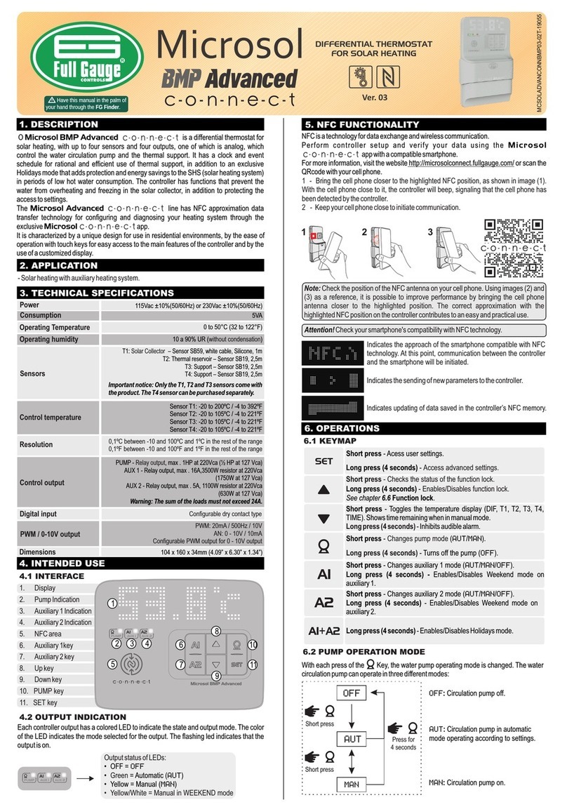
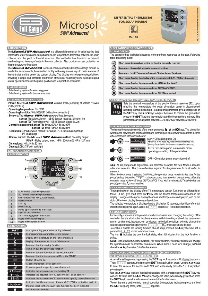
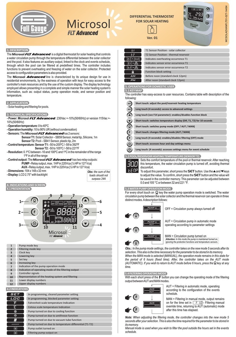
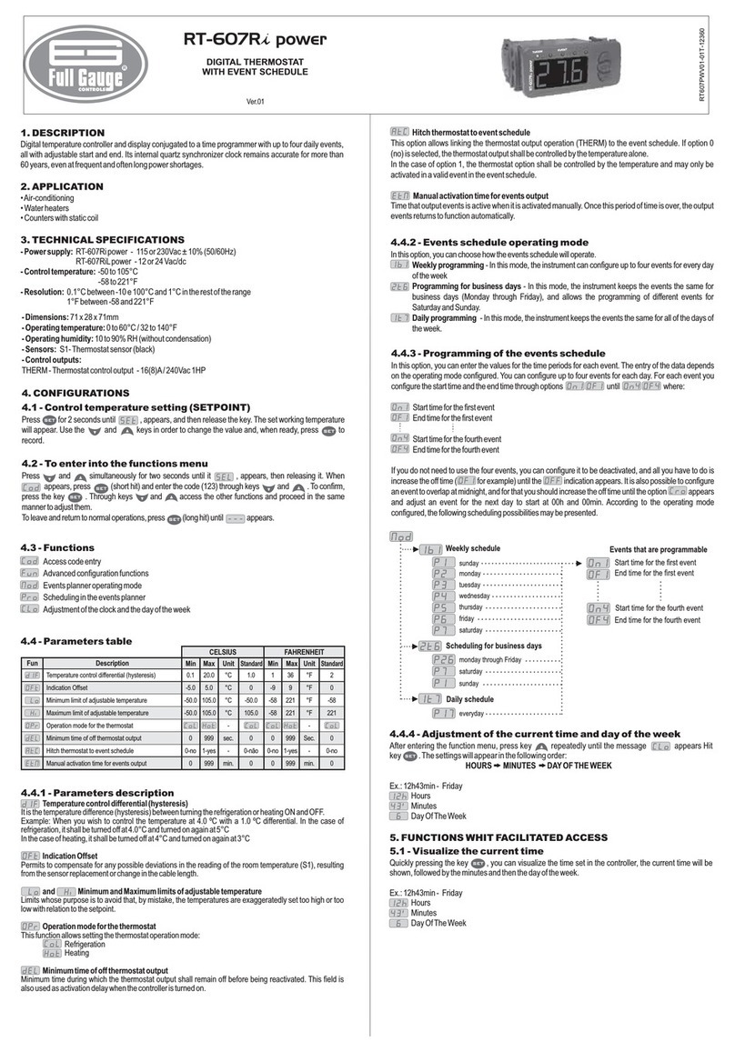
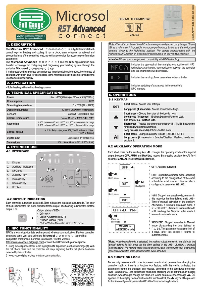
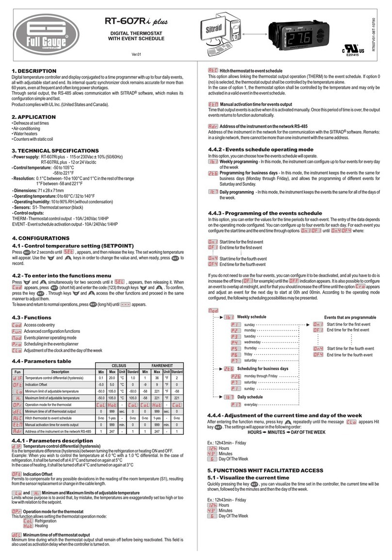
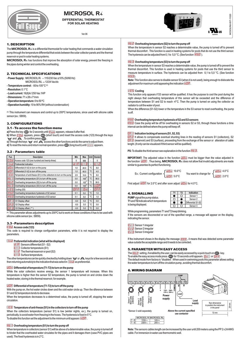
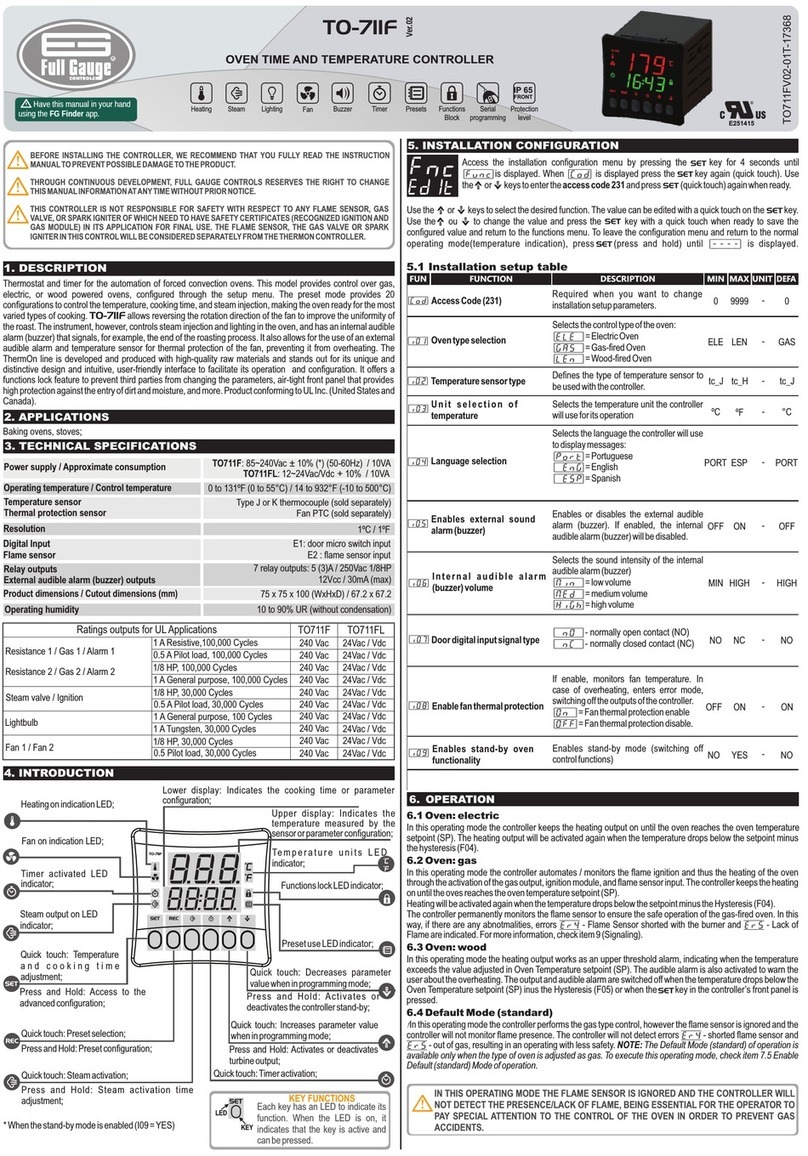
The Microsol RST Advanced is a digital thermostat with control logic for
heating or cooling. The unit is equipped with a clock, events schedule for rational and
economical use of the controlled load, and protected access to configuration parameters.
It features the Holiday function which saves on power consumption during periods when
the system is idle.
The Microsol Advanced line is characterized by its unique design for use in
residential environments, by the easiness of operation with keys for easy access to the
controller's main resources and by the use of the custom display. The display technology
employed allows presenting in a complete and simple manner the solar heating system's
information, such as: output status, thermostat operation mode, sensor temperature and
time.
2. APPLICATION
- Heating systems for thermal reservoirs
- Floor heating
- Air conditioning
3. TECHNICAL SPECIFICATIONS
- Power: Microsol RST Advanced: 230Vac +-10%(50/60Hz) or version 115Vac
+-10%(50/60Hz)
- Operation temperature: 0 to 40ºC
- Operation humidity: 10 to 90% UR (without condensation)
- Sensors: The Microsol RST Advanced has 1 sensor:
Sensor T1: Thermostat - SB41 Sensor, plastic tip, 2m
- Control temperature: Sensor T1: -50 to 105ºC / -58 to 221ºF
- Resolution: 0.1ºC between -10 and 100ºC and 1ºC in the remainder of the range
1ºF in all of the range
- Control output: The Microsol RST Advanced has one relay output:
AUX - Relay output, max. 16A, resistance
3500W in 220Vca (1750W in 127 Vca)
- Dimensions: 104 x 148 x 32 mm
- Display: LCD 2.75'' with backlight
5. OPERATIONS FOR DOMESTIC USER
5.1 KEY MAP
The controller has easy-access to user resources. Contains table with description of the
following:
Short key press: set the thermostat temperature
Long touch (4 seconds): access to advanced settings
Long touch (see F10 parameter): enables/disables function block
Short key press: access the menu to set the events schedule
Short touch: switches way thermostat mode (AUT / MAN)
Long key press (4 seconds): enables/disables thermostat Holiday mode (OFF)
Short touch: accesses hour and day settings menu
DIGITAL THERMOSTAT
WITH EVENTS SCHEDULE
Ver. 02
SET
SET
RST Advanced
4. INDICATIONS AND SCREEN
4.1 PRESENTATION
1
2
3
4
5
6
7
8
9
10
11
Schedule key
Thermostat mode key
Clock key
Lowering key
Set key
Increasing key
Indication of the thermostat operation mode
Controller signals
Representation of the solar heating system
Lower display numbers
Upper display numbers
4.2 INDICATIONS
SET
LOC
5.2 THERMOSTAT TEMPERATURE
Sets the operating temperature of the thermostat.
To adjust this parameter, short press the SET button. Use the and keys to
adjust the value. To confirm, short press the SET button and the value will be
saved in the controller memory. This parameter can be adjusted between the
values defined in the advanced configuration for parameters: [,F03] –
Minimum value of the thermostat temperature and [,F04] – Maximum value
of the thermostat temperature.
5.3 THERMOSTAT OPERATING MODE
With each short press of the button you can change the operating mode of the
thermostat output between AUT and MAN modes.
Note: When adjusting the thermostat mode, the controller changes into the new mode 5
seconds after your selection. This is also the time required for the parameter to be stored in
its memory.
Manual mode is used when you wish to control the load outside the hours set in the events
schedule.
In manual mode, the thermostat output is still associated to the sensor temperature via the
thermostat heating temperature ([TEMP] parameter). In this mode, the controller allows
the output to be turned on during the period programmed in the parameter [,F05].
AUX
AUT
AUX
MAN
SET
AUT = Thermostat in automatic mode, operating
according to the configuration of the events
schedule and sensor temperature.
MAN = Thermostat in manual mode. It remains in
this mode for the time set in [,F05]- thermostat
manual override time, and returns to AUT mode
after this time has elapsed.
5.3.1 VACATION MODE
To enable/disable the Vacation mode, the key must be held for 4 seconds.
OFF: vacation mode enabled.
When enabled:
The event schedule is ignored, the support outlet is turned off, resulting in energy
consumption reduction.
Obs.: In thermostat mode settings, the controller takes on the new mode 5 seconds after
its selection. This also is the time necessary for the parameter to be stored in its memory.
4 seconds
off
AUX
A
SET
1
2
3
6
5
4
AUX
am pm
SET LOC
AUX
AUT
off
MAN
am pm
7
11
8
910
A
A
A
A
am
pm
AUX
In programming, cleared parameter setting
In programming, blocked parameter setting
Fahrenheit scale temperature Indication
Celsius scale temperature Indication
Thermostat output on, if F01=Cool
Thermostat output on, if F01=Heat
Indicates the occurrence of a controller error
Function block setting
Before noon (standard clock 12pm)
After noon (standard clock 12pm)
RST
AUX
AUX
AUT
Obs.: In the parameter menu, to leave and return to normal operation (preferential
indication of temperature and time) maintain the SET key pressed (long touch) until the
message [----] appears. When the Fahrenheit temperature scale is selected, the
clock acquires the 12h standard, and the AM and PM icons are used for time indication. In
this scale, the Time and Day messages of the parameter description are replaced by Time
and Day in the controller display.
5.5 EVENT SCHEDULE SETTINGS
If it is not necessary to use all 4 events, you should set these in the turned off state, by just
increasing the final time until [,OFF]appears. It is possible to set an event that begins in
one day and finishes in another. To do so you should raise the final event time until
[,CRo]appears and set on the following day the initial event with time on [00:00].
To set the event schedule associated to the thermostat outlet, you should hold the key.
The schedule allows setting up to 4 events for each day of the week, as the programming
performed in parameter [,F06] - thermostat event schedule operation mode. Each
event is comprised by a final and initial schedule.
The event schedule gets factory settings in mode [,1t7], same events for each day of
the week, and the schedules are defined as follows:
Initial time for the
1st event
End time for the
1st event
Initial time for the
2st event
End time for the
2st event
End time for the
3st event
Initial time for the
3st event
End time for the
4st event
Initial time for the
4st event
am pm
Short
touch
2 seconds
am pm
am pm
SET
Long touch
Preferential
indication
Weekly
programming
Sunday
Monday
Tuesday
Wednesday
Thursday
Friday
Saturday
SET
Short touch
SET
Long touch
According to the set operation mode, the following programming possibilities may be
presented:
Programmed case [,F06] = [,1B1]
Programmed case [,F06] = [,2T6]
SET
Adjustment
Short touch
SET
Adjustment
Short touch
SET
Adjustment
Short touch
SET
Adjustment
Short touch
am pm
Short
touch
2 seconds
SET
Long touch
Preferential
indication
Weekday
Programming
am pm
am pm
Sunday
Weekdays
Saturday
SET
Short touch
SET
Long touch
SET
Adjustment
Short touch
SET
Adjustment
Short touch
SET
Adjustment
Short touch
SET
Adjustment
Short touch
Programmed case [,F06] = [,1T7]
am pm
Short
touch
2 seconds
Preferential
indication
Daily
programming
SET
Adjustment
Short touch
SET
Short touch
1 second
1 second
SET
Long touch
Adjustment
SET
Adjustment
Short touch
SET
Short touch
1 second
Adjustment
5.6 FUNCTION BLOCK
For security reasons and in order to avoid unauthorized people changing the controller
settings, there is the function block resource. With that setting activated, the parameters
cannot be changed, but they can be displayed, however. In the block condition, upon trying
to change the value of a parameter the message "[,LOC][,,ON]no display " will be
displayed.
To enable/disable the function block you should hold the key for the time set in parameter
key for the time set in parameter [,F14] – Time for function block. The icon indicates
the block state to the user, in case it is accessed, it indicates that the function block is
active.
HINT: with active function block one avoids that children, visitors or curious people change
the operation mode or the controller parameters. When some change is needed, just hold
the key to enable/disable this resource.
6. ADVANCED OPERATIONS FOR THE INSTALLER (TECHNICAL USE)
6.1 CONTROLLER PARAMETERS CHANGE
Access the settings menu holding the SET key for 4 seconds until [FuNc] appears.
After that [Code] will appear and then press once again the SET key, short touch. Use
the or keys to enter the access code value, 123, and when ready press the SET key
once again (short touch). Use the or keys to select the desired function. With a short
touch to the SET key it’s possible to edit its value. Use the or keys to change the
value, and when ready give a short touch on the SET key to memorize the set value and
return to the function menu.
To leave the menu and return to normal operation (temperature indication) hold the SET
key (long touch) until [----]appears
- Upon accessing the parameter settings, the upper display will flash and over
it the SET icon is displayed, indicating that it is possible to change the
parameter value.
Observations:
SET
am pm
- If the 123 code has not been inserted, upon accessing the parameter settings
the icon will be displayed over the upper display, indicating that the
setting is locked.
- With active function block, upon pressing the or keys to change the
function value, the controller will display the[,LOC][,,On]message on
the screen and it won't be possible to perform the parameter setting.
LOC
LOC
LOC
5.4 TIME AND DAY SETTINGS
In order to access the Time and Day menu, just give a short touch on the key. Through
the or keys it is possible to navigate among the parameters. In order to edit them press
the SET key and through the or keys update its value. The values will flash in
adjustment mode. Confirm the time value with the key. After the confirmation, adjust SET
the day and confirm with the key again to exit the adjustment modeSET .
NOTICE:
The controller has an internal auxiliary power supply to maintain the clock during
power failure for at least 72 hours. If the controller remains turned off for a
prolonged period of time, it will display the message [ECLO], indicating that the
clock is deprogrammed. In this situation the controller's date and time must be set,
keeping it energized for 10 hours so that the auxiliary source is fully recharged.
Clock - Time settings.
Day - Day of the week settings.
Adjustable from 1 (Sunday) to 7 (Saturday).
SET
SET
6.3 DESCRIPTION OF PARAMETERS
[Code]– Access code (123):
Required when you want to change the advanced configuration parameters. This code is not required
to only view the set parameters.
[,F01] – Thermostat control logic:
Sets the operating logic of the thermostat.
[Cool]– Cooling.
[Heat]– Heating.
[,F02] – Thermostat temperature hysteresis ([TEMP] parameter):
Temperature difference to turn on the thermostat. This function allows you to define a temperature
range within which the output will remain off.
For example: If set to [temp]=[,45.0],[,f02]=[,,2.0] and [,f01]=[heat] the thermostat
output will be turned off when the T1 sensor temperature reaches 45.0 °C, and will only turn on when
this falls below 43.0 °C (45.0-2.0=43.0).
[,F03] – Minimum allowable setting for the thermostat temperature:
[,F04] – Maximum allowable setting for the thermostat temperature:
These parameters serve as upper and lower limits for adjusting the [TEMP] parameter (thermostat
heating temperature). They are used to block temperature adjustment so as to prevent an inappropriate
configuration, for example. A high value could mean the thermostat output stays on for a long time,
resulting in high power consumption.
[,F05] – Thermostat manual override time:
Used when you wish to activate the output outside the hours set in the events schedule. When using
manual override, the thermostat returns to AUT (automatic) mode after the time programmed in this
parameter. To disable this function, move the setting to the minimum until[,,No] appears.
[,F06] – Events schedule operating mode:
Sets the operating mode of the events schedule:
[,1b1] – Weekly Programming – in this mode, the instrument can set up to 4 different
events for each day of the week.
[,2t6] – Weekday Programming – in this mode, the instrument keeps events the same on
weekdays (Monday to Friday) and allows you to program different events for Saturday and
Sunday.
[,1t7] – Daily Programming – in this mode, the instrument keeps the events the same for
every day of the week.
Note: When changing the mode of the events schedule, the controller loads the events with
default values.
[,F07] – Thermostat output linked to the events schedule:
This option lets you link the operation of the thermostat output to the events schedule.
[,OFF]– the thermostat output is controlled only by temperature.
[,,ON]– the thermostat output is controlled by temperature and by the events schedule.
Note: If set to OFF, the controller will indicate AUT for the thermostat mode.
[,F08] – Thermostat temperature in economy mode:
Determines the temperature setpoint that the controller uses as a reference when in AUT mode and no
event is active or when Holiday mode (OFF) is selected. This feature is preferably used for floor heating
applications where, outside the ranges defined in the events schedule, the temperature control takes
on a setpoint with a lower value in order to maintain the floors pre-heated and enable rapid heating of
the environment when necessary.
To disable this function, move the setting to the minimum until [,,No] appears, turning off the
temperature control in Holiday mode or when no event is active, a mode preferably used to heat thermal
reservoirs.
[,f09] - Recirculation - Scan time (if F01 = Heat):
Time during which the controller keeps the water circulation activated to equalize the water
temperature in the keg.
This function can be switched off by setting it at the minimum value 0 [no,,].
[,F10] - Interval between scans (if F01 = Heat):
It is the interval between the last and the next temperature scan.
NOTE: If the temperature to switch on the thermostat is reached the scan cycle is restarted.
[,F11] - Maximum time the thermostat output remains on without reaching the setpoint (if F01
= Heat):
It is the maximum time the thermostat output will remain on without reaching the setpoint during the
heating process. When this time is exceeded, the thermostat output is turned off according to the time
set in [,f12]. Functions [,F12] and [,F13] serves as protections for the gas-fired heater so that
in the event of fault (flame out for instance), the water circulation is interrupted and the heater is
switched off to protect it.
This function can be switched off by setting it at the minimum value 0 [no,,].
6.4 UNIT SELECTION
To define the temperature unit with which the instrument is going to operate you should
access the [Code] function (see article 6.1 to find out how to access this function), insert
the 231 code and press the key. The user may select the unit by pressing the keys or ,
where the messages [,=C,]or[,=F,]are alternated. Press the SET key to confirm
the desired unit. Next the message[----]will be displayed and the{or }icons
corresponding to the unit will be turned on.
Obs.: While changing the unit, the controller carries the factory values in its parameters,
[,FAC], being necessary to perform their setting.
7. SIGNALS
- Motive: Sensor 1 disconnected or out of the specified range.
- Motive: Dis-programmed clock due to prolonged energy absence.
- Corrective measures: Check the connections and sensor operation.
- Corrective measures: Adjust time and day, see article 5.5.
am
- Motive: Manual thermostat activation with parameter settings
[,F05]=[,,no].
- Corrective measures: Set parameter value F05 - Time of manual
thermostat activation.
- Motive: Attempted exchange the mode of thermostat with parameter
adjustment [,F07] = [,OFF].
- Corrective measures: Check parameter F07 – Thermostat output
linked to the events schedule
6.2 TABLE OF PARAMETERS
Min Max Unit Min Max Unit
Standard
CELSIUS FAHRENHEIT
Fun
[CoDE]
[,F01]
[,F02]
[,F03]
[,F04]
[,F05]
[,F06]
[,F07]
[,F08]
[,F09]
[,F10]
[,F11]
[,f12]
[,f13]
[,f14]
[,f15]
Standard
Description
Access code
Thermostat control logic
Thermostat temperature hysteresis
Minimum allowable setting for the thermostat temperature (TEMP parameter)
Maximum allowable setting for the thermostat temperature (TEMP parameter)
Thermostat manual override time
Events schedule operating mode
Thermostat output linked to the events schedule
Thermostat temperature in economy mode
Recirculation - Scan time
Interval between scans
Maximum time the thermostat output remains on without reaching the setpoint
Thermostat output off time in state of alarm for not reaching the setpoint
T1 Sensor indication displacement (Offset)
Function lock time
Intensity of the display backlight
0
Cool
0.1
-50
-50
no (0)
1b1
Off
no (-11)
no (0)
no (0)
no (0)
no (0)
-5.0
no (3)
Eco (0)
999
Heat
20.0
105
105
600
1t7
On
30.0
999
999
120
120
5.0
30
10
-
-
ºC
ºC
ºC
min
-
-
ºC
min.
min.
min.
min.
ºC
s
-
0
Heat
2.0
0.0
50.0
120
1t7
On
no
no (0)
no (0)
no (0)
no (0)
0.0
10
Eco (0)
0
Cool
1
-58
-58
no (0)
1b1
Off
no (12)
no (0)
no (0)
no (0)
no (0)
-9
no (3)
Eco (0)
999
Heat
36
221
221
600
1t7
On
86
999
999
120
120
9
30
10
-
-
ºF
ºF
ºF
min
-
-
ºF
min.
min.
min.
min.
ºF
s
-
0
Heat
3
32
122
120
1t7
On
no
no (0)
no (0)
no (0)
no (0)
0
10
Eco (0)
- C orrective measures: Contact the technician responsible for
installation.
[,F12] - Thermostat output off time in state of alarm for not reaching the setpoint (if F01 =
Heat):
It allows adjusting the time for which the controller will keep the thermostat output off while in state of
alarm for not reaching the setpoint. If the setpoint is reached during this time the alarm is switched off. If
the setpoint is not reached after this time has elapsed, new checks are performed during the time
defined in [,F11].
NOTE: This function takes precedence over the recirculation functions [,f09] and [,f10].
[,F13] – T1 Sensor indication displacement (Offset):
Used to compensate for possible deviations in the sensor reading as a result of sensor replacement or
changing the cable length.
[,F14] – Function lock time:
Sets the time that the increment button must be pressed in order to lock/unlock parameter changes. For
more information see item 5.6 – Function Lock. To disable this function, move the setting to the
minimum until [,,No] appears.
[,F15]– Intensity of the display backlight:
If the value adjusted in this function is the minimum [,ECO], the intensity of the backlight of the display
will decrease to the minimum value (1) if no key is pressed for 5 seconds, If any key is pressed, the
intensity will increase to (8).
Obs.: In the occurrence of any error information the controller signals the user, flashing the
display's backlight shortly, in order to grab attention.
- C orrective measures: Contact the technician responsible for
installation.
9 10 11
115 Vac
or
230 Vac
0
Power supply
NOTE: check supply as product model
Turn off the network
before removing
the protection cover.
1 2 34 5 678
POWER
SUPPLY
SENSOR T1
PLASTIC TIP
(THERMOSTAT)
THERM
LOAD
ENVIRONMENTAL INFORMATION
Packaging:
The materials used in the packaging of Full Gauge products are 100% recyclable. Try to
perform disposal through specialized recyclers.
Product:
The components used in Full Gauge controllers can be recycled and reused if
disassembled by specialized companies.
Disposal:
Do not incinerate or dispose the controllers that have reached the end of their service as
household garbage. Observe the laws in your area regarding disposal of electronic
waste. If in doubt, please contact Full Gauge Controls.
WARRANTY - FULL GAUGE CONTROLS
Products manufactured by Full Gauge Controls, as of May 2005, have a two (02)
yearwarranty, as of the date of the consigned sale, as stated on the invoice. They are
guaranteed against manufacturing defects that make them unsuitable or inadequate for their
intended use.
EXCEPTIONS TO WARRANTY
The Warranty does not cover expenses incurred for freight and/or insurance when sending
products with signs of defect or faulty functioning to an authorized provider of technical
support services. The following events are not covered either: natural wear and tear of parts;
external damage caused by falls or inadequate packaging of products.
LOSS OF WARRANTY
Products will automatically lose its warranty in the following cases:
- The instructions for assembly and use found in the technical description and installation
procedures in Standard IEC60364 are not obeyed;
- The product is submitted to conditions beyond the limits specified in its technical
description;
- The product is violated or repaired by any person not a member of the technical team of
Full Gauge Controls;
- Damage has been caused by a fall, blow and/or impact, infiltration of water, overload
and/or atmospheric discharge.
USE OF WARRANTY
To make use of the warranty, customers must send the properly packaged product to Full
Gauge Controls together with the invoice or receipt for the corresponding purchase. As
much information as possible in relation to the issue detected must be sent to facilitate
analysis, testing and execution of the service.
These procedures and any maintenance of the product may only be provided by Full
Gauge Controls Technical Support services in the company's headquarters at Rua Júlio de
Castilhos, 250 - CEP 92120-030 - Canoas - Rio Grande do Sul – Brasil
Rev. 03
9. IMPORTANT
According to the chapters of norm IEC 60364:
1: Install protector against overvoltage on the power supply.
2: Sensor cables and signal cables of the computer may be joined, but not in the same
electric conduit through which the electric input and the activation of the loads run.
3: Install transient suppresors (RC filters) parallel to the loads as to increase the product
life of the relays.
Contact suppressor connection diagram
Suppressor
A1
A2
A1 and A2 are the
contactor coils.
Diagram for suppressor installation for direct
drive load inputs
Load
Suppressor
For direct activation the maximum
specified current should be taken
into consideration.
Suppressors on offer from Full Gauge Controls
8.3 ELECTRICAL CONNECTIONS
8. INSTALLATION
8.1 SUPERIMPOSED INSTALLATION
Push the bottom openings
necessary for the passage of
cables;
Attach the controller to the wall using the
screws and plugs provided;
Make the electrical
connections of the controller;
For a better finish
install X system type
channels to run
cables;
Place the protective cover of
the electrical connections
and secure it with the screw
(included in package).
8.2 INSTALLATION OF 4x2 BOX
The top screw must not be screwed
completely, for engaging the
controller. After fitting the controller
on the top screw, secure it with the
lower screw;
Push the rear openings
necessary for the passage
of cables;
Route the cables through the
openings as controller connections;
Secure the controller in
4x2 box using the
screws provided;
Place the
protective cover
of the electrical
connections and
secure it with the
screw (included
in package).
Make the electrical
connections of the controller;
The top screw must
not be screwed
completely, for
engaging the controller. After
fitting the controller on the top screw,
secure it with the lower screw;
Copyright 2013 All rights reserved.
Remove the protective
cover of the
connections at the
bottom of the controller;
Remove the protective
cover of the connections
at the bottom of the
controller;
A qualified technician must perform
the installation of the device.
DO DON’Ts
The controller MUST be installed:
- indoors, in a dry environment;
- away from electromagnetic fields;
- in a ventilated place, free from flammable
liquids and gases;
- protected by a circuit breaker of appropriate
specification for the installed load.
The controller MUST NOT be
installed:
- in wet places;
- exposed to sunlight or rain;
- in saunas, machine rooms or
bathrooms.
1
2
3
4
5
6
1
2
3
4
5
6
s
Failure to not comply the warnings will cause loss of warranty, equipment and / or
physical damage.
Note: The length of the sensor cable can be increased by the user up to 200 meters using PP 2 x 24
AWG cable.

Other Full Gauge Controls Thermostat manuals

Full Gauge Controls Microsol FLT Advanced User manual

Full Gauge Controls

Full Gauge Controls Microsol FLT Advanced User manual

Full Gauge Controls RT-607RiL power User manual

Full Gauge Controls

Full Gauge Controls RT-607RiL power User manual

Full Gauge Controls Microsol RST Advanced c-o-n-n-e-c-t User manual

Full Gauge Controls

Full Gauge Controls Microsol RST Advanced c-o-n-n-e-c-t User manual

Full Gauge Controls Microsol SWP Advanced c-o-n-n-e-c-t User manual

Full Gauge Controls

Full Gauge Controls Microsol SWP Advanced c-o-n-n-e-c-t User manual

Full Gauge Controls Microsol BMP Advanced User manual

Full Gauge Controls

Full Gauge Controls Microsol BMP Advanced User manual

Full Gauge Controls Microsol Ri User manual

Full Gauge Controls

Full Gauge Controls Microsol Ri User manual

Full Gauge Controls ANASOL 115vac Operator's manual

Full Gauge Controls

Full Gauge Controls ANASOL 115vac Operator's manual

Full Gauge Controls Microsol BMP Advanced c-o-n-n-e-c-t User manual

Full Gauge Controls

Full Gauge Controls Microsol BMP Advanced c-o-n-n-e-c-t User manual

Full Gauge Controls TO-711F User manual

Full Gauge Controls

Full Gauge Controls TO-711F User manual

Full Gauge Controls Microsol Ri User manual

Full Gauge Controls

Full Gauge Controls Microsol Ri User manual

Full Gauge Controls Microsol SWP Advanced User manual

Full Gauge Controls

Full Gauge Controls Microsol SWP Advanced User manual

Full Gauge Controls RT-607Ri plus User manual

Full Gauge Controls

Full Gauge Controls RT-607Ri plus User manual

Popular Thermostat manuals by other brands

Daikin EKRTW installation manual

Daikin

Daikin EKRTW installation manual

Watts Wattstemp 740 user guide

Watts

Watts Wattstemp 740 user guide

Levoit Aura Sensor user manual

Levoit

Levoit Aura Sensor user manual

Honeywell FocusPRO TH5000 Series installation guide

Honeywell

Honeywell FocusPRO TH5000 Series installation guide

Chromalox DSR-5716P Installation and operation instructions

Chromalox

Chromalox DSR-5716P Installation and operation instructions

ritetemp 8029B install guide

ritetemp

ritetemp 8029B install guide

Daikin 668811101 Installation, operation & application guide

Daikin

Daikin 668811101 Installation, operation & application guide

Honeywell RTH9580 Wi-Fi user guide

Honeywell

Honeywell RTH9580 Wi-Fi user guide

Horstmann C-Stat 11-M installation instructions

Horstmann

Horstmann C-Stat 11-M installation instructions

Honeywell INNCOM e7w user guide

Honeywell

Honeywell INNCOM e7w user guide

ICMA 88P4160199 user manual

ICMA

ICMA 88P4160199 user manual

EWC Controls EWT-755WHO installation manual

EWC Controls

EWC Controls EWT-755WHO installation manual

Heatmiser DT-TS WiFi RF manual

Heatmiser

Heatmiser DT-TS WiFi RF manual

Selmo SMART Plus ClassII FP manual

Selmo

Selmo SMART Plus ClassII FP manual

ClimateMaster ATC32U01 iGate installation manual

ClimateMaster

ClimateMaster ATC32U01 iGate installation manual

Aprilaire 8537 Specifications

Aprilaire

Aprilaire 8537 Specifications

Living Heat SmartLife CT1000 manual

Living Heat

Living Heat SmartLife CT1000 manual

Pro1 Technologies T701i Product installation guide

Pro1 Technologies

Pro1 Technologies T701i Product installation guide

manuals.online logo
manuals.online logoBrands
  • About & Mission
  • Contact us
  • Privacy Policy
  • Terms and Conditions

Copyright 2025 Manuals.Online. All Rights Reserved.