manuals.online logo
Brands
  1. Home
  2. •
  3. Brands
  4. •
  5. Full Gauge Controls
  6. •
  7. Thermostat
  8. •
  9. Full Gauge Controls RT-607RiL power User manual

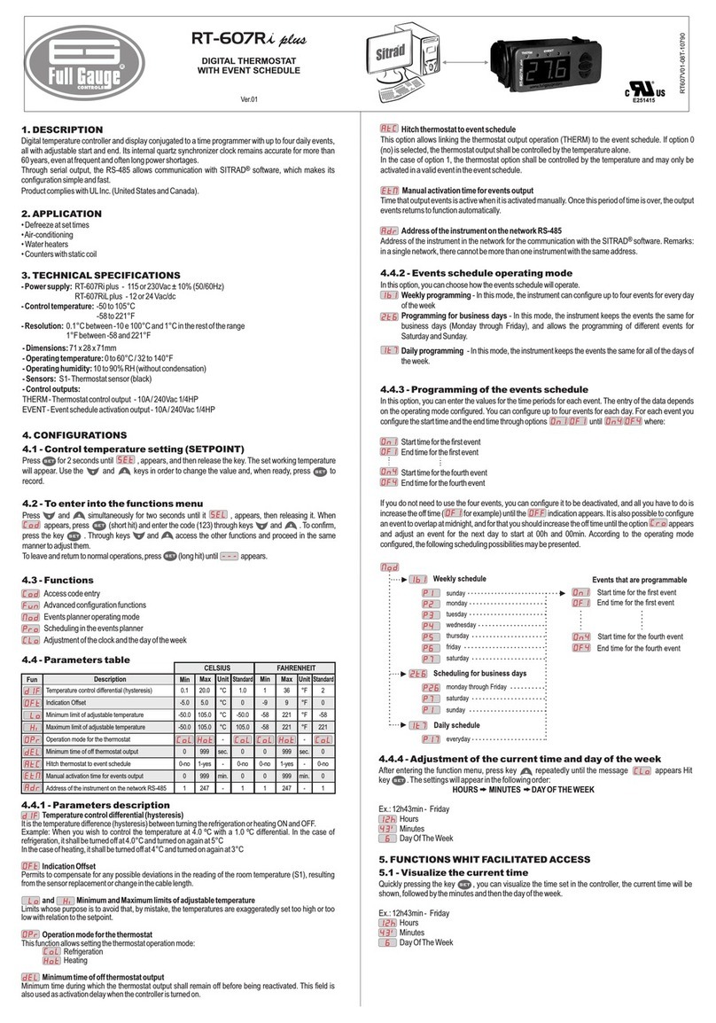
Full Gauge Controls RT-607RiL power User manual

Ver.01
DIGITAL THERMOSTAT
WITH EVENT SCHEDULE
1. DESCRIPTION
Digital temperature controller and display conjugated to a time programmer with up to four daily events,
all with adjustable start and end. Its internal quartz synchronizer clock remains accurate for more than
60 years, even at frequent and often long power shortages.
•Air-conditioning
• Water heaters
• Counters with static coil
RT-607Ri power - 115 or 230Vac ± 10% (50/60Hz)
RT-607RiL power - 12 or 24 Vac/dc
-50 to 105°C
58 to 221°F
0.1°C between -10 e 100°C and 1°C in the rest of the range
1°F between -58 and 221°F
2. APPLICATION
3. TECHNICAL SPECIFICATIONS
- Power supply:
- Control temperature:
- Resolution:
-
- Dimensions:
- Operating temperature:
- Operating humidity:
- Sensors:
- Control outputs:
71 x 28 x 71mm
0 to 60°C / 32 to 140°F
10 to 90% RH (without condensation)
S1- Thermostat sensor (black)
THERM - Thermostat control output - 16(8)A/ 240Vac 1HP
Press for 2 seconds until , appears, and then release the key. The set working temperature
will appear. Use the and keys in order to change the value and, when ready, press to
record.
Press and simultaneously for two seconds until it , appears, then releasing it. When
appears, press (short hit) and enter the code (123) through keys and . To confirm,
press the key . Through keys and access the other functions and proceed in the same
manner to adjust them.
To leave and return to normal operations, press (long hit) until appears.
4. CONFIGURATIONS
4.1 - Control temperature setting (SETPOINT)
4.2 - To enter into the functions menu
SET
SET
SET
SET
SET
4.3 - Functions
Access code entry
Advanced configuration functions
Events planner operating mode
Scheduling in the events planner
Adjustment of the clock and the day of the week
Description Min Max Unit
CELSIUS
Fun
Standard Standard
Min Max Unit
FAHRENHEIT
0.1
-5.0
-50.0
-50.0
0
0-no
0
20.0
5.0
105.0
105.0
999
1-yes
999
°C
°C
°C
°C
-
sec.
-
min.
°F
°F
°F
°F
-
Sec.
-
min.
36
9
221
221
999
1-yes
999
1
-9
-58
-58
0
0-no
0
2
0
-58
221
0
0-no
0
4.4 - Parameters table
4.4.1 - Parameters description
Temperature control differential (hysteresis)
Indication Offset
and Minimum and Maximum limits of adjustable temperature
Operation mode for the thermostat
Minimum time of off thermostat output
It is the temperature difference (hysteresis) between turning the refrigeration or heating ON and OFF.
Example: When you wish to control the temperature at 4.0 ºC with a 1.0 ºC differential. In the case of
refrigeration, it shall be turned off at 4.0°C and turned on again at 5°C
In the case of heating, it shall be turned off at 4°C and turned on again at 3°C
Permits to compensate for any possible deviations in the reading of the room temperature (S1), resulting
from the sensor replacement or change in the cable length.
Limits whose purpose is to avoid that, by mistake, the temperatures are exaggeratedly set too high or too
low with relation to the setpoint.
This function allows setting the thermostat operation mode:
Refrigeration
Heating
Minimum time during which the thermostat output shall remain off before being reactivated. This field is
also used as activation delay when the controller is turned on.
Hitch thermostat to event schedule
Weekly programming
Programming for business days
Daily programming
This option allows linking the thermostat output operation (THERM) to the event schedule. If option 0
(no) is selected, the thermostat output shall be controlled by the temperature alone.
In the case of option 1, the thermostat option shall be controlled by the temperature and may only be
activated in a valid event in the event schedule.
In this option, you can choose how the events schedule will operate.
- In this mode, the instrument can configure up to four events for every day
of the week
- In this mode, the instrument keeps the events the same for
business days (Monday through Friday), and allows the programming of different events for
Saturday and Sunday.
- In this mode, the instrument keeps the events the same for all of the days of
the week.
4.4.2 - Events schedule operating mode
Manual activation time for events output
Time that output events is active when it is activated manually. Once this period of time is over, the output
events returns to function automatically.
4.4.3 - Programming of the events schedule
In this option, you can enter the values for the time periods for each event. The entry of the data depends
on the operating mode configured. You can configure up to four events for each day. For each event you
configure the start time and the end time through options until where:
Start time for the first event
End time for the first event
Start time for the fourth event
End time for the fourth event
If you do not need to use the four events, you can configure it to be deactivated, and all you have to do is
increase the off time ( for example) until the indication appears. It is also possible to configure
an event to overlap at midnight, and for that you should increase the off time until the option appears
and adjust an event for the next day to start at 00h and 00min. According to the operating mode
configured, the following scheduling possibilities may be presented.
4.4.4 - Adjustment of the current time and day of the week
5. FUNCTIONS WHIT FACILITATED ACCESS
5.1 - Visualize the current time
After entering the function menu, press key repeatedly until the message appears Hit
key . The settings will appear in the following order:
Ex.: 12h43min - Friday
Hours
Minutes
Day Of The Week
Quickly pressing the key , you can visualize the time set in the controller, the current time will be
shown, followed by the minutes and then the day of the week.
Ex.: 12h43min - Friday
Hours
Minutes
Day Of The Week
HOURS MINUTES DAY OF THE WEEK
SET
SET
RT-607Ri power
Temperature control differential (hysteresis)
Indication Offset
Minimum limit of adjustable temperature
Maximum limit of adjustable temperature
Operation mode for the thermostat
Minimum time of off thermostat output
Hitch thermostat to event schedule
Manual activation time for events output
1.0
0
-50.0
105.0
0
0-não
0
RT607PWV01-01T-12360
THERM EVENT
IMPORTANT
1:
2:
3:
According to the chapters of norm IEC 60364:
Install on the power supply
Sensor cables and signal cables of the computer may be joined, but not in the same electric conduit
through which the electric input and the activation of the loads run
Install transient suppresors (RC filters) parallel to the loads as to increase the product life of the
relays.
protector against overvoltage
Schematic for the connection of supresors
to contactors
Suppresor
A1
A2
A1 and A2 are the
contactor coil terminals.
Schematic for the connection of supresors to
direct activation loads
Load
Suppresor
For direct activation the maximum
specified current should be taken
into consideration.
PROTECTIVE VINYL:
This adhesive vinyl (included inside the packing) protects the instruments against
water drippings, as in commercial refrigerators, for example.
Do the application after finishing the electrical connections.
Remove the protective paper
and apply the vinyl on the entire
superior part of the device,
folding the flaps as indicated by
the arrows.
5.2 - View maximum and minimum temperature
6. SIGNALLING
By pressing key one can view the minimum and maximum thermostat temperature. On pressing key
(short touch), the minimum temperature shall be displayed, followed by the maximum temperature.
If the key remains pressed in, the values will be reinitialized and the message will be shown in
the display.
- Thermostat sensor disconnected or out of range
- Configuration parameters not programmed or out of range
Led - Currently active eventEVENT
5.3 - Manual events activation
Pressing the key for 10 seconds, manually activate an event. It will be deactivated after the time
adjusted in the function elapses .
If the key is pressed again for 10 seconds, the manual drive will be disabled.
To deactivate the manual activation, all you have to do is configure function with the value " 000".
The display will show the message when the manual drive is enabled and the message
when the manual drive is disabled.
8. WIRING DIAGRAM
72 mm
29 mm
Dimension of the clipping
for setting of the instrument
in panel
7. UNIT SELECTION(°C / °F)
To define the unit that the system will use to operate, enter into the functions menu using the
access code ”231” and confirm it by hitting key . The indication will appear, then press
or to choose between or and confirm with key . After selecting the unit the
figure will appear, and the instrument will return to the function . Whenever the unit is
altered, the parameters should be reconfigured, since they assume “standard” values.
SET
SET
Sensor
Power
supply
Load
COMMON
Load
supply
NO
NC
12345678910 11 12
115 V
(12 V)
230 V
(24 V)
0
THERM
7-8
7-9
115V
230V
12V
24V
RT-607Ri power RT-607RiL power

This manual suits for next models

1

Other Full Gauge Controls Thermostat manuals

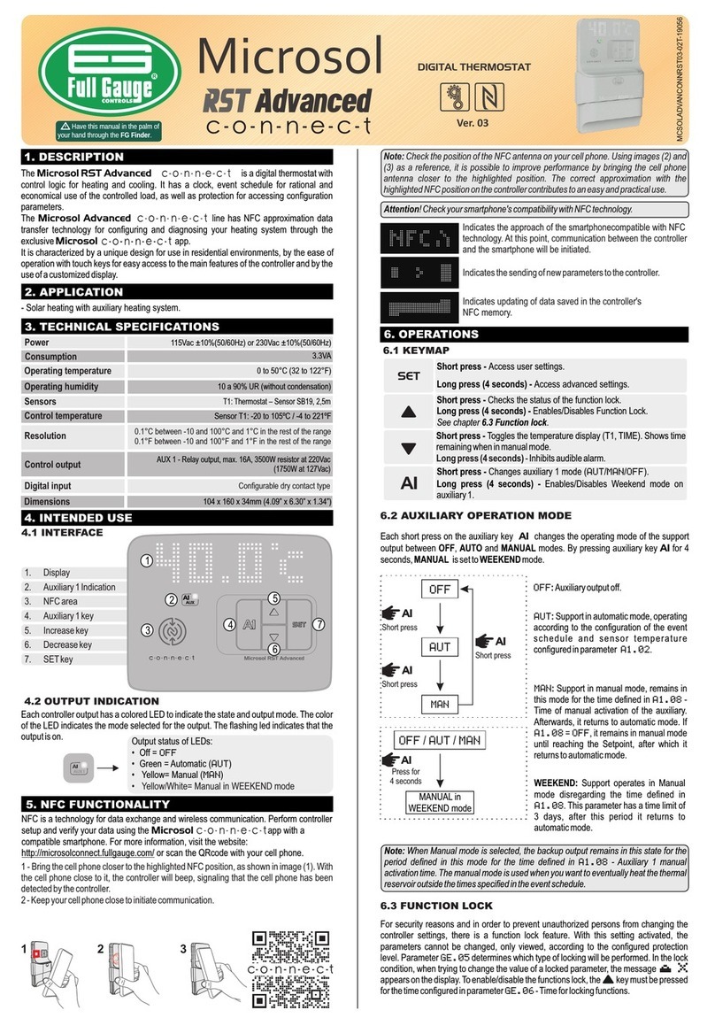
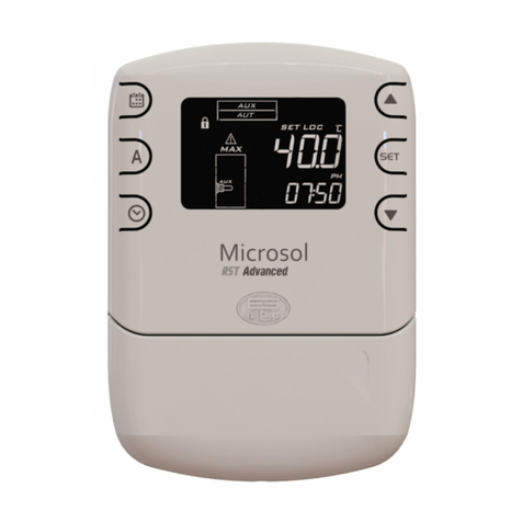
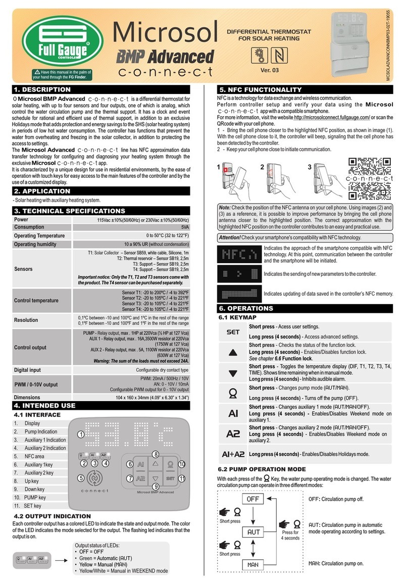
Full Gauge Controls Microsol RST Advanced c-o-n-n-e-c-t User manual

Full Gauge Controls

Full Gauge Controls Microsol RST Advanced c-o-n-n-e-c-t User manual

Full Gauge Controls Microsol Ri User manual

Full Gauge Controls

Full Gauge Controls Microsol Ri User manual

Full Gauge Controls Microsol Ri User manual

Full Gauge Controls

Full Gauge Controls Microsol Ri User manual

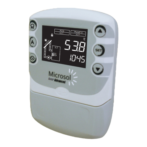
Full Gauge Controls Microsol BMP Advanced User manual

Full Gauge Controls

Full Gauge Controls Microsol BMP Advanced User manual

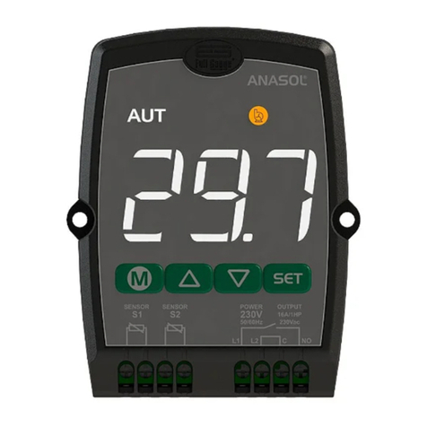
Full Gauge Controls ANASOL 115vac Operator's manual

Full Gauge Controls

Full Gauge Controls ANASOL 115vac Operator's manual

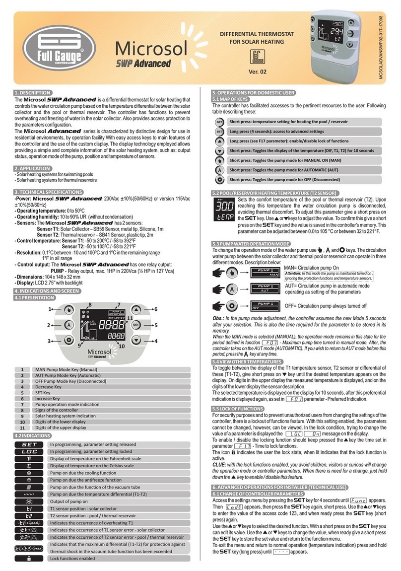
Full Gauge Controls Microsol SWP Advanced User manual

Full Gauge Controls

Full Gauge Controls Microsol SWP Advanced User manual

Full Gauge Controls Microsol BMP Advanced c-o-n-n-e-c-t User manual

Full Gauge Controls

Full Gauge Controls Microsol BMP Advanced c-o-n-n-e-c-t User manual

Full Gauge Controls Microsol FLT Advanced User manual

Full Gauge Controls

Full Gauge Controls Microsol FLT Advanced User manual

Full Gauge Controls Microsol RST Advanced User manual

Full Gauge Controls

Full Gauge Controls Microsol RST Advanced User manual

Full Gauge Controls RT-607Ri plus User manual

Full Gauge Controls

Full Gauge Controls RT-607Ri plus User manual

Full Gauge Controls Microsol SWP Advanced c-o-n-n-e-c-t User manual

Full Gauge Controls

Full Gauge Controls Microsol SWP Advanced c-o-n-n-e-c-t User manual

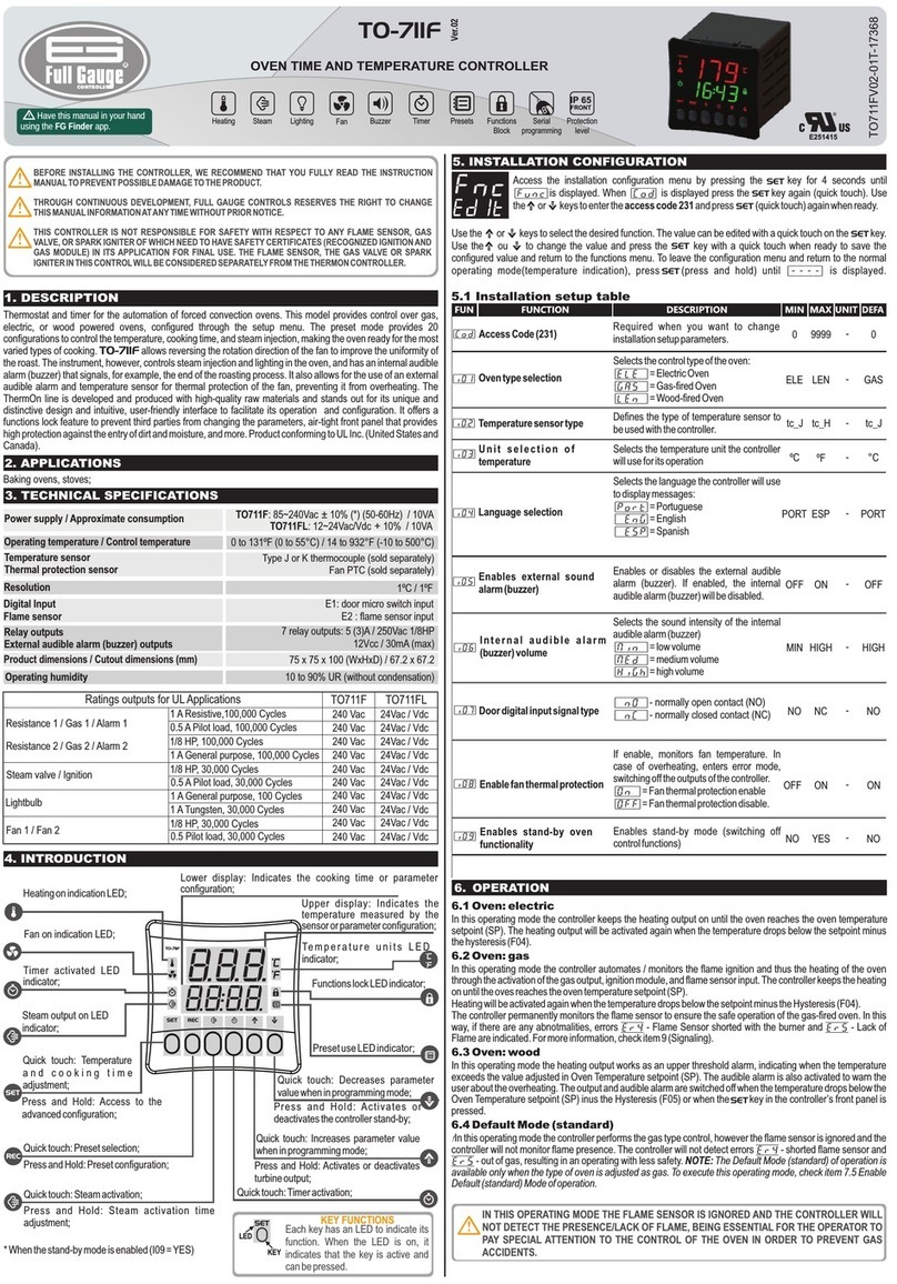
Full Gauge Controls TO-711F User manual

Full Gauge Controls

Full Gauge Controls TO-711F User manual

Popular Thermostat manuals by other brands

Honeywell INTELLIGUARD 9000 user guide

Honeywell

Honeywell INTELLIGUARD 9000 user guide

Enernet T9000 user guide

Enernet

Enernet T9000 user guide

Honeywell Home TL8230A1003 owner's guide

Honeywell Home

Honeywell Home TL8230A1003 owner's guide

Carrier A07051 installation instructions

Carrier

Carrier A07051 installation instructions

sisel Enda EDT5411A quick start guide

sisel

sisel Enda EDT5411A quick start guide

Belimo EXT-RCF-24 installation manual

Belimo

Belimo EXT-RCF-24 installation manual

Everwell LP260 installation instructions

Everwell

Everwell LP260 installation instructions

Danfoss TP7000 Series user guide

Danfoss

Danfoss TP7000 Series user guide

Tekmar 519 user manual

Tekmar

Tekmar 519 user manual

Heatstore HSUFCDC Installation and operating instructions

Heatstore

Heatstore HSUFCDC Installation and operating instructions

Salus AWRT10RF quick start guide

Salus

Salus AWRT10RF quick start guide

Aube Technologies TH140-28 Installation and user guide

Aube Technologies

Aube Technologies TH140-28 Installation and user guide

Hvac R Series installation instructions

Hvac

Hvac R Series installation instructions

Honeywell FocusPRO 5000 quick guide

Honeywell

Honeywell FocusPRO 5000 quick guide

Home Automation RC-120 owner's manual

Home Automation

Home Automation RC-120 owner's manual

Vimar 02972 Installer manual

Vimar

Vimar 02972 Installer manual

Heatmiser Touch Series manual

Heatmiser

Heatmiser Touch Series manual

RCS TZ45 Installation and operation manual

RCS

RCS TZ45 Installation and operation manual

manuals.online logo
manuals.online logoBrands
  • About & Mission
  • Contact us
  • Privacy Policy
  • Terms and Conditions

Copyright 2025 Manuals.Online. All Rights Reserved.