Funk Amateur DYC-8x7 2.0 User manual

Dynamikkompressor
DYC
-
8x7 2.0
Hocheffizienter externer Dynamikkom ressor
mit dem SSM2165P von Analog Devices für die
Yaesu-Transceiver FT-817, FT-857 und FT-897
Bauanleitung

2 • BX-8x7 © Box 73 Amat urfunks rvic GmbH 2014
The kit for this dynamic compressor was
originally introduced in [1] based on an
idea of Phil Salas, AD5X. It was develo-
ped especially for the FT-817, but can al-
so be used for other transceivers with the
same microphone interface, such as the
FT-857, FT-897 or FT-900.
The dynamic compressor is plugged in
between the microphone and the transcei-
ver. It does not require a separate power
supply, and can be switched on or off as
needed. No modifications to the original
microphone or to the transceiver are re-
quired.
The integral AF tone generator, which fa-
cilitates antenna tuning in SSB mode, can
be keyed via two existing buttons on the
microphone. As a result, the general prac-
tice of whistling for tuning is no longer re-
quired.
With the exception of one tantalum capa-
citor, the S D components are preassem-
bled. Only a few wired components re-
main; these can be easily installed even by
less experienced builders.
Construction Manual for
Dynamic Compressor V2.0 for FT-8x7
When ransmi ing SSB, a dynamic compressor increases average rans-
mi ed power, and hus he audibili y of a weak signal a he dis an re-
ceiver, by a leas one S-uni . This accessory is of special in eres o
ama eur radio opera ors who work wi h lower ransmi ing power or wish
o be be er heard in a pile-up.

BX-8x7 • 3© Box 73 Amat urfunks rvic GmbH 2014
Der Bausatz für diesen Dynamikkompres-
sor basiert auf einer Idee von Phil Salas,
AD5X, und wurde ursprünglich in [1] vor-
gestellt. Er war seinerzeit speziell für den
FT-817 vorgesehen, ist aber auch an ande-
ren Transceivern verwendbar, die über die
gleiche ikrofonschnittstelle verfügen,
wie z. B. FT-857, FT-897 oder FT-900.
Der Dynamikkompressor wird in die Lei-
tung zwischen ikrofon und Transceiver
eingeschleift, benötigt keine separate
Stromversorgung und ist bei Bedarf zu-
oder abschaltbar. odifikationen am Ori-
ginalmikrofon oder am Transceiver sind
nicht erforderlich.
Der integrierte NF-Generator lässt sich
mithilfe zweier Tasten am ikrofon zu-
schalten und erleichtert auf diese Weise
das Abstimmen der Antenne in der Sende-
art SSB. Das oft praktizierte Abstimm-
Pfeifen wird damit überflüssig.
Die S D-Bauelemente sind, bis auf einen
Tantal-Elko, bereits vorbestückt. Es blei-
ben somit nur noch einige bedrahtete Bau-
teile übrig, die sich auch vom weniger ge-
übten Bastler relativ einfach verarbeiten
lassen.
Figure 1:
A dynamic compres-
sor, ully assembled
and ready to use
Bild 1:
Dynamikkompressor
im ertig au gebauten
und einsatzbereiten
Zustand
Ein Dynamikkompressors erhöh bei der Sendear SSB die durch-
schni liche Sendeleis ung und dami die Vers ändlichkei eines schwa-
chen Empfangssignals um mindes ens eine S-S ufe. Dami is dieses Zu-
sa zgerä speziell für Funkama eure in eressan , die mi kleiner Sende-
leis ung arbei en oder im Pile-up besser gehör werden wollen.
Bauanleitung um Dynamikkompressor
2.0 für FT-8x7
FA-LESERSERVICE

4 • BX-8x7 © Box 73 Amat urfunks rvic GmbH 2014
■Circuit
Figure 2 shows the AF dynamic compres-
sor’s schematic. Its central feature is the
special Analog Devices SS 2165 micro-
phone preamplifier [2]. This IC has a gain
of 18 dB, which is compensated for by the
R10/R11 voltage divider. The level of the
AF signal can be changed, and thereby ca-
librated to the transceiver input when col-
lector resistance in the low-noise pre-am-
plifier stage has been set with potentiome-
ter P1. The Switch S1is used to turn the
compressor function on and off, and along
with potentiometer P2 sets the desired
compression ratio. Three of the four
NAND gates on C OS chip IC2 form the
AF generator, which can be activated by
simultaneously pressing the PTT and
Down microphone buttons.
The compressor is powered from the inter-
nal 5V DC rail of the connected transcei-
ver. Current consumption is approximate-
ly 10 mA.
Figure 2: Dynamic compressor schematic

BX-8x7 • 5© Box 73 Amat urfunks rvic GmbH 2014
■Schaltung
In Bild 2 ist die Schaltung des NF-Dyna-
mikkompressors zu sehen. Herzstück ist
der Spezialschaltkreis SS 2165 [2]. Er
hat eine Verstärkung von 18 dB, die mit
dem Spannungsteiler R10/R11 wieder
kompensiert wird. it dem als Einstellwi-
derstand P1 ausgeführten Kollektorwider-
stand der rauscharmen Vorverstärkerstufe
lässt sich der Pegel des NF-Signals verän-
dern und somit an den Transceivereingang
anpassen. Der Umschalter S1 dient zum
Ein- und Ausschalten der Kompressor-
funktion und mit dem Einstellwiderstand
P2 kann man das gewünschte Kompres-
sionsverhätnis einstellen. Drei der insge-
samt vier NAND-Gatter des C OS-
Schaltkreises IC2 bilden den NF-Genera-
tor, der durch gleichzeitiges Drücken der
ikrofontasten PTT und Down aktiviert
werden kann.
Ihre Betriebsspannung von 5 V bezieht die
Schaltung vom nachgeschalteten Trans-
ceiver. Die Stromaufnahme beträgt etwa
10 mA.
Bild 2: Schaltplan des Dynamikkompressors

6 • BX-8x7 © Box 73 Amat urfunks rvic GmbH 2014
■Construction
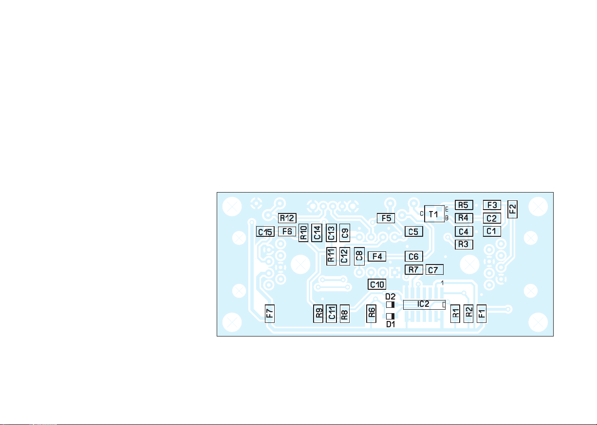
After checking all parts against the parts
list, you may begin assembly of the circu-
it board. You will need a temperature-con-
trolled low-voltage soldering iron, 1 mm
dia. rosin-cored solder, a pair of tweezers
and a small pair of wire-cutters.
Warning! When working on the board, be
sure that it is not exposed to undue me-
chanical stress. Strong pressure, which
causes transverse deflection on the board,
should be avoided. Lengthwise rotation
(torsion) should be avoided as well.
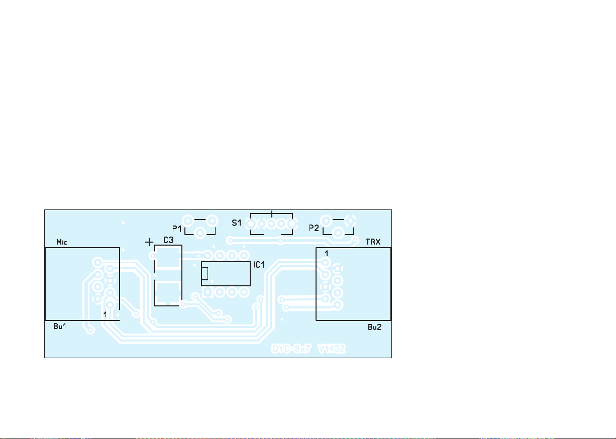
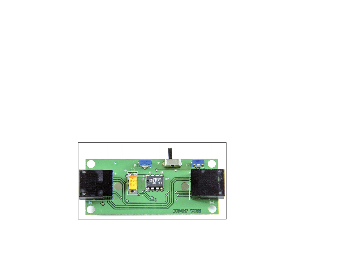
Both RJ45 sockets are already inserted on
the board, so only the eight pins of each
socket need to be soldered to the board
Next, tantalum capacitor C3 is installed.
Its positive pole is marked with a dash,
and its correct positioning can be seen in
Figures 3 and 4 of the assembly guide.
When soldering C3, proceed as follows:
First, tin the solder pad of the terminal to
the board. Then, center the capacitor and
its solder connections over the board’s two
solder pads. These have been intentional-
ly designed to be slightly larger than ne-
cessary in order to facilitate soldering the
capacitor. Next, heat the previously tinned
solder pad with a soldering iron and, in
this way, “tack” it to the capacitor. If the
capacitor is sitting incorrectly, it can still
be straightened at this stage. If everything
fits, solder the negative pole and subse-
quently, the positive pole.
This is followed by IC1 (installation posi-
tion in accordance with assembly guide),
the two potentiometers P1 (1 k) and P2
(100 k) and the miniature slide switch S1.
Along with the box, the latter should sit
flat on the circuit board so that the hori-
zontal lever later fits through the opening
in the box.
Now, the protruding leads of P1, P2 and
S1 located on the solder side in the imme-
diate vicinity of the board edge, must be
carefully cut flush with the board using
wire cutters so that the board fits nicely in-
to the bottom half of the box when assem-
bled.

BX-8x7 • 7© Box 73 Amat urfunks rvic GmbH 2014
■Au bau
Nach der Überprüfung der Vollzähligkeit
aller Bauteile anhand der Stückliste kann
man mit der Bestückung der Platine be-
ginnen. Dazu werden ein geregelter
Niederspannungslötkolben, 1-mm-Löt-
draht mit Flussmittelseele, eine Pinzette
sowie ein kleiner Seitenschneider benö-
tigt.
Achtung! Bei Arbeiten an der Platine ist
darauf zu achten, dass diese keinen über-
mäßigen mechanischen Belastungen aus-
gesetzt wird. Starker Druck, der zum
Durchbiegen der Leiterplatte in Querrich-
tung führt, ist ebenso zu vermeiden wie
ein Verdrehen in Längsrichtung.
Die beiden RJ45-Buchsen sind bereits auf
die Platine gesteckt, sodass nur noch die
jeweils 8 Anschlüsse zu verlöten sind.
Zweckmäßigerweise bestückt man dann
den Tantal-Elektrolytkondensator C3.
Dessen Pluspol ist mit einem Querstrich
gekennzeichnet. Seine korrekte Positio-
nierung ist sowohl im Bestückungsplan
Bild 3 als auch in Bild 4 ersichtlich.
Beim Einlöten von C3 geht man wie folgt
vor: Zuerst wird das Lötpad des Pluspols
auf der Platine verzinnt. Anschließend
setzt man den Kondensator mit seinen
Lötanschlüssen mittig auf die beiden Löt-
flächen der Platine. Diese sind absichtlich
etwas größer als erforderlich dimensio-
niert, um das Einlöten des Kondensators
zu vereinfachen. Nun wird das zuvor ver-
zinnte Lötpad mit dem Lötkolben erwärmt
und auf diese Weise der Kondensator „an-
geheftet“. Falls er doch noch schief sitzen
sollte, lässt sich das jetzt noch korrigieren.
Wenn alles passt, lötet man jetzt den i-
Bild 3: Bestückungsplan des Dynamikkompressors (Oberseite der Platine)
Figure 3: Assembly diagram (PCB, top side)

8 • BX-8x7 © Box 73 Amat urfunks rvic GmbH 2014
Bild 3a: Bestückungsplan der SMD-Bauelemente (Unterseite der Platine)
Figure 3a: Assembly diagram o SMD parts (PCB, bottom side)

BX-8x7 • 9© Box 73 Amat urfunks rvic GmbH 2014
nuspol an und den Pluspol noch einmal
nach.
Es folgen IC1 (Einbaulage gemäß Bestü-
ckungsaufdruck beachten!), die beiden
unterschiedlichen Einstellwiderstände P1
(1 k) und P2 (100 k) sowie der iniatur-
Schiebeschalter S1. Letzterer sollte mit
seinem Gehäuse flach auf der Platine sit-
zen, damit der waagerecht liegende
Schalthebel später durch die Öffnung im
Gehäuse passt.
Nun sind noch die in unmittelbarer Nähe
des Platinenrandes befindlichen Bauele-
menteanschlüsse von P1, P2 und S1 auf
der Platinenunterseite mit dem Seiten-
schneider vorsichtig zu kürzen, damit die
Platine später gut in die Unterschale des
Gehäuses passt.
Figure 4:
Fully assembled
printed circuit board
(top)
Bild 4:
Vollständig bestückte
Platine (Oberseite)

10 • BX-8x7 © Box 73 Amat urfunks rvic GmbH 2014
■Start-Up
Before the compressor is connected to the
transceiver for the first time, current con-
sumption should be checked. To do this,
you will need a 5V laboratory power sup-
ply and a multimeter with a current mea-
suring range.
The required operating voltage connection
can be made with two thin wires provisio-
nally soldered across C3. The multimeter,
connected in series, should show a current
of 10 mA to 12 mA. A significantly diffe-
rent value points to an assembly error. Be-
fore moving on, it is necessary to find and
fix this error. Particular attention should
be paid to proper mounting and clean sol-
der joints.
Warning! If you connect the dynamic
compressor to the transceiver despite ex-
cessive current consumption, the transcei-
ver may be damaged.
Potentiometers P1 and P2 are set at mid-
range from the factory. P1 and P2 alrea-
dy produce a clearly perceptible effect in
this position. For this reason, the first tests
should be conducted at this setting. If the
microphone level is too high or low at this
stage, it can be corrected with P1. Refer to
the guide in the section on operating in-
structions when adjustingthe compression
ratio with P2.
■Box installation
To install the unit inside the box, the as-
sembled board is placed inside the lower
half of the shell (Figure 5). The upper half
of the shell is placed on the lower half.
Both halves of the box have corresponding
sockets and pins to ensure firm cohesion.
It is not necessary to affix the board to the
box with additional screws. After pressing
the two halves together and applying the
label, the dynamic compressor is ready for
use (Figure 1).

BX-8x7 • 11© Box 73 Amat urfunks rvic GmbH 2014
■Inbetriebnahme
Bevor der Kompressor zum ersten al an
den Transceiver angeschlossen wird, soll-
te man die Stromaufnahme überprüfen.
Dazu werden ein 5-V-Labornetzgerät und
ein ultimeter mit Strommessbereich be-
nötigt.
Der dazu erforderliche Betriebspannungs-
anschluss kann mit zwei dünnen Drähten
erfolgen, die man parallel zu C3 proviso-
risch angelötet. Das in Reihe geschaltete
ultimeter sollte einen Strom von 10 mA
bis 12 mA anzeigen. Ein deutlich abwei-
chender Wert weist auf einen Aufbaufehler
hin. Dieser Fehler ist zunächst zu finden
und zu beheben. Besonderes Augenmerk
ist dabei auf die korrekte Bestückung und
auf saubere Lötstellen zu legen.
Achtung! Sollten Sie den Dynamikkom-
pressor trotz einer möglicherweise zu ho-
hen Stromaufnahme an den Transceiver
anschließen, kann der Transceiver beschä-
digt werden.
Die Einstellwiderstände P1 und P2 befin-
den sich bei Auslieferung in ittelstel-
lung. Schon so ergibt sich ein deutlich
wahrnehmbarer Effekt. Die ersten Tests
sollte man deshalb auch mit dieser Ein-
stellung vornehmen. Wenn sich dabei
zeigt, dass der ikrofonpegel zu gering
oder zu hoch ist, kann dieser mit P1 korri-
giert werden. Zur Einstellung der Kom-
pression mit P2 sind die Hinweise im Ab-
schnitt Betriebshinweise zu beachten.
■Einbau in das Gehäuse
Zum Einbau in das Gehäuse wird die be-
stückte Platine in die Unterschale gelegt
(Bild 5) und die Oberschale daraufgesetzt.
Beide Gehäusehälften verfügen über
Buchsen und Zapfen, die einen festen Zu-
sammenhalt gewährleisten. Eine Fixie-
rung der Platine mit Schrauben ist nicht
erforderlich. Nach dem Zusammendrü-
cken der beiden Gehäuseschalen und dem
Aufbringen des Aufklebers ist der Dyna-
mikkompressor einsatzbereit (Bild 1).
Figure 5:
Lower part o
the box with inlaid
circuit board
Bild 5:
Gehäuseunterschale
mit eingesetzter
Platine

12 • BX-8x7 © Box 73 Amat urfunks rvic GmbH 2014
■Operating Instructions
The AF dynamic compressor DYC-8x7 is
looped into the microphone lead of the ori-
ginal Yaesu H-31A8J microphone. It is
not suited for use with the optional DT F
microphone.
To connect to the transceiver, one of the
two plugs on the supplied short cable must
be inserted into the dynamic compressor’s
TRX socket. The other plug must be in-
serted into the transceiver’s microphone
jack. The plug on the microphone cable is
then inserted into the IC port on the
compressor. When the transceiver is tur-
ned on, the DYC-8x7 is ready for use. The
position of slide switch S1determines
whether the microphone signal is com-
pressed (ON) or not (OFF).
The compression ratio can be adjusted to
individual requirements by varying the re-
sulting resistance between Pin 6 on the
IC1 and levels in the range of 47 kΩ to 147
kΩ. The result is that the compression ra-
tio’s adjustment range runs from 4:1 to
9:1, which is sufficient for all cases.
Especially at low SSB signal received
strength, dynamic compression has a posi-
tive effect on speech intelligibility. Distant
stations will notice a signal strength in-
crease of about 1 S-unit (6 dB), and the in-
crease in loudness may be even higher.
The dynamic compressor should not be
turned on for F , as there are no resulting
benefits. On the contrary, the signal quali-
ty will be degraded on the receiving end.
The same applies to SSB paths with good
audibility. The compressor comes into its
own with signals at the limit of audibility.
It should not be turned on in any other ca-
se.
When using 100W transceivers, it is parti-
cularly important to note that any shortco-
mings in the station setup cannot be com-
pensated for with the use of the dynamic
compressor. This mainly concerns poorly
engineered antennas without adequate RF
ground and E C issues such as RF feed-
back via the microphone cable, which can
cause problems especially when used with
a linear amplifier.

BX-8x7 • 13© Box 73 Amat urfunks rvic GmbH 2014
■Betriebshinweise
Der NF-Dynamikkompressor DYC-8x7
wird in die ikrofonleitung des Original-
Yaesu- ikrofons H-31A8J einge-
schleift. Er eignet sich nicht für das optio-
nal erhältliche DT F- ikrofon!
Für den Anschluss an den Transceiver ist
einer der beiden Stecker des mitgelieferten
kurzen Kabels in die Buchse TRX des Dy-
namikkompressors zu stecken. Der andere
Stecker kommt in die ikrofonbuchse des
Transceivers und der Stecker des ikro-
fonkabels wiederum in die Buchse IC
des Kompressors. Bei eingeschaltetem
Transceiver ist auch der DYC-8x7 sofort
betriebsbereit. Die Stellung des Schiebe-
schalters S1 entscheidet darüber, ob das
ikrofonsignal komprimiert wird (ON)
oder nicht (OFF).
Das Kompressionsverhältnis lässt sich den
individuellen Vorstellungen anpassen, in-
dem man den resultierenden Widerstand
zwischen Pin 6 des IC1 und asse im Be-
reich von 47 kΩ bis 147 kΩ variiert. Dar-
aus resultiert ein Einstellbereich des Kom-
pressionsverhältnisses von 4:1 bis 9:1,
was für alle Fälle ausreicht.
Besonders bei niedriger Empfangsfeld-
stärke von SSB-Signalen wirkt sich der
Effekt der Dynamikkompression positiv
auf die Sprachverständlichkeit aus.
Gegenstationen registrieren am S- eter
einen Signalanstieg von bis zu 6 dB, die
gehörmäßige Zunahme der Lautstärke
kann sogar noch höher sein.
Bei F sollte man den Dynamikkompres-
sor nicht einschalten, denn er bringt bei
F keine Vorteile – ganz im Gegenteil, da
auf der Empfangsseite die Signalqualität
schlechter wird. Gleiches gilt für SSB-
Verbindungen mit guter Hörbarkeit. Seine
Stärke entfaltet der Kompressor erst bei
Funkverbindungen an der Grenze der Hör-
barkeit des Signals. In allen anderen Fäl-
len sollte er nicht eingeschaltet werden.
Es ist besonders bei 100-W-Transceivern
zu beachten, dass man eventuelle Unzu-
länglichkeiten des Stationsaufbaus durch
das Zuschalten des Dynamikkompressor
nicht ausgleichen kann. Das betrifft haupt-
sächlich schlecht abgestimmte unsymme-
trische Antennen ohne ausreichende HF-
Erde und stark in das ikrofonkabel ein-
strahlende Antennenspeiseleitungen, was
insbesondere bei Verwendung einer Li -
nearendstufe Probleme verursachen kann.

14 • BX-8x7 © Box 73 Amat urfunks rvic GmbH 2014
Additionally, the DYC-8x7 contains a
simple AF generator. This can be used to
generate a stable test tone for tuning an-
tennas, ATU’s or linear amplifiers, for
example. The AF generator is activated by
pressing the Down button on the micro-
phone while the PTT button is already de-
pressed. This can be done with one hand.
Please be sure to keep such tuning signals
as brief as possible and at the lowest pos-
sible RF power level, so as not to interfe-
re with other radio communications.
The standard functions of the microphone
buttons (Up, Down and Start Search) re-
main intact.
At high AF gain or when using the maxi-
mum compression level, be sure to listen
to your own transmitted signal and ask the
distant operator for an audio report. High
AF gain can cause background noise to
overwhelm the compressor circuit’s filter
threshold and be transmitted, especially
when a high compression ratio has been
set. This should be strictly avoided.
Good luck and have fun putting the kit to-
gether and using your dynamic compres-
sor on the air!
suppor @funkama eur.de
Lit ratur
[1] Theurich, K., DG0ZB: Dynamikkompressor für
den FT-817. FUNKA ATEUR 51 (2002) No. 4,
p. 389
[2] FA-Bauelementeinformation SS 2165: FUNK -
A ATEUR 50 (2001) No. 12, p. 1357
Parts list
Nam Mod l/Valu Numb r Comm nt
IC1 SS 2165-1P 1
C3 220 µF/10V 1 Tantalum
P1 Potentiometer 1 kΩ1
P2 Potentiometer 100 kΩ1
S1 Slide switch, 1-pin 1
Bu1, Bu2 RJ45 jack 2 on the board
Circuit board Circuit board 1 S Ds mounted
TRX connector cable 1 with 2 ¥RJ45
Box 1 processed
Label 1
Construction manual 1

BX-8x7 • 15© Box 73 Amat urfunks rvic GmbH 2014
Zusätzlich enthält der DYC-8x7 einen ein-
fachen NF-Generator. it ihm kann man
ein stabiles Sendesignal erzeugen, um
zum Beispiel Antennen anzupassen. Der
NF-Generator wird aktiviert, indem man
bei gedrückter PTT- zusätzlich die Down-
Taste am ikrofon betätigt, was mit einer
Hand gut gelingt. Bitte achten Sie darauf,
solche Abstimmsignale so kurz wie mög-
lich und nur mit der minimal erforder-
lichen Sendeleistung abzustrahlen, um an-
dere Funkverbindungen nicht zu stören.
Die ursprünglichen Funktionen der Tasten
am ikrofon (Up, Down und Suchlauf-
start) bleiben erhalten.
Bei hoch eingestellter NF-Verstärkung
oder bei maximalem Kompressionsgrad
sollten Sie sich das eigene Sendesignal un-
bedingt selbst anhören und den Funkpart-
ner um die Beurteilung der Signalqualität
bitten. Hohe NF-Verstärkung kann näm-
lich dazu führen, dass Hintergrundgeräu-
sche die Filterschwelle des Kompressor-
schaltkreises überwinden und dann – vor
allem bei hoch eingestelltem Kompres-
sionsverhältnis – auch abgestrahlt werden.
Dies sollte unbedingt vermieden werden.
Viel Spaß und Erfolg beim Aufbau des
Bausatzes und beim Funkbetrieb mit Ih-
rem Dynamikkompressor!
suppor @funkama eur.de
Lit ratur
[1] Theurich, K., DG0ZB: Dynamikkompressor für
den FT-817. FUNKA ATEUR 51 (2002) H. 4,
S. 389
[2] FA-Bauelementeinformation SS 2165: FUNK -
A ATEUR 50 (2001) H. 12, S. 1357
Stücklist d r im Bausatz nthalt n n Baut il
B z ichnung Typ/W rt Anzahl B m rkung
IC1 SS 2165-1P 1
C3 220µF/10V 1 Tantal
P1 Trimmer 1 kΩ1
P2 Trimmer 100 kΩ1
S1 Schiebeschalter, 1-polig 1
Bu1, Bu2 RJ45-Buchse 2
Platine Platine 1 S D-bestückt
Anschlusskabel zum TRX 1 konfektioniert (2 ¥RJ45)
Gehäuse 1 bearbeitet
Aufkleber 1
Baumappe 1

Bei der Entsorgung dieses Produkts sind die Bestimmungen
zum Umgang mit Elektronikschrott zu beachten.
Elektronische Geräte, Batterien usw. gehören keinesfalls in
den Hausmüll.
Box 73 Amateurfunkservice GmbH
ajakowskiring 38
13156 Berlin
www.funkamateur.de Stand: Juni 2014
Table of contents
Languages:
Popular Air Compressor manuals by other brands

Delta
Delta Oil-Free 66-651 instruction manual

ALLPOWER
ALLPOWER apc4200 owner's manual

airmaster
airmaster TIGER 16/550 Operation & maintenance instructions

Central Pneumatic
Central Pneumatic Central Pneumatic 30 Gallon, 180 PSI Gas Powered Two-Stage Air... manual

ALLPOWER
ALLPOWER 3.5HP PEAK 6 GALLON owner's manual

Central Pneumatic
Central Pneumatic 94724 operating instructions