FunkTronic Major BOS 2b2 User manual

Major BOS 2b2
Serial Number 3799 and later

- 2 - mbos2b_short_eng (22.11.2010)
Kompetent für Elektroniksysteme
mbos2b_short_eng (22.11.2010)
- 3 -
Kompetent für Elektroniksysteme
Content
Technical Data 2
Controls of Major BOS 2b2 3
Major BOS 2b2 4
Connectivity 4
Keys 4
Carrier Indication (Squelch) 4
Transmitter Indication (PTT) 4
Selection Indication 4
Microphone Selection 5
Tone Call Decoder 5
Tone Call Encoder 5
Technical Data
Supply Voltage +12V DC -15% +25%
Current consumption max. 1000 mA
AF input level
Recommended value for earpiece AF 500 mV (at 10 kOhm)
Input impedance approx. 10 kOhm
AF output level
Factory default 500 mV at 200 Ohm
Range 300mV to 700mV
Output impedance (Transmitting) approx. 200 Ohm
Output impedance (Receiving) high impedance (disconnected)
Tape Recorder output level
Factory default - 6 dBm (at 600 Ohm)
Range (Potentiometer P8) - 14 dBm to - 2 dBm (at 600 Ohm)
Output impedance approx. 600 Ohm
Weight (without cable) approx. 1650 g
Size (without gooseneck microphone)
W x D x H 245 x 220 x 90 mm
Page

- 2 - mbos2b_short_eng (22.11.2010)
Kompetent für Elektroniksysteme
mbos2b_short_eng (22.11.2010)
- 3 -
Kompetent für Elektroniksysteme
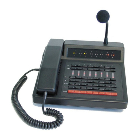
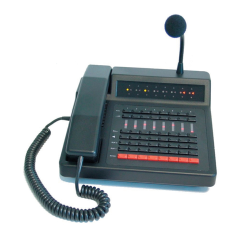
Controls of Major BOS 2b2
12 3
6
7
8
12
11
1 - Transmitter indication
2 - Selection indication
3 - Receiver indication (Squelch)
4 - Selection key
5 - Monitoring volume
6 - PTT key
7 - Tone Call key (Call I and Call II)
8 - Master volume
9 - Loudspeaker
10 - PTT key handset
11 - Handset
12 - Gooseneck microphone
4
10
9
5

- 4 - mbos2b_short_eng (22.11.2010)
Kompetent für Elektroniksysteme
mbos2b_short_eng (22.11.2010)
- 5 -
Kompetent für Elektroniksysteme
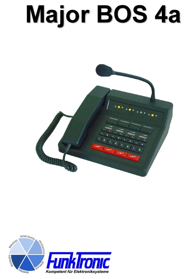
Major BOS 2b2
Connectivity
This desktop radio contoller can be connected to up to four two way radios. Every base station can be
supplied with squelch input, PTT output, a busy line and AF ins and outs. In addition the Major BOS
2b2 provides a headset connector, an external signal encoder imput and a tape recorder output. It is
possible to connect the unit to a PC via RS232 interface for programming purposes.
It is possible to operate multiple Major BOS2b2 in parallel circuit because AF outputs are internally
disconnected in idle or receiving mode.
Keys
The keboard presents four selection keys for the max. of four radio devices, two tone call keys and
the red PTT key.
Carrier Indication (Squelch)
Every one of the four radio circuits provides its own carrier indicator (Squelch), which is located above
the corresponding selection key. For activation the squelch input needs a voltage between 5V and
14V. The logic of the carrier indication is configurable. The polarirty of the carrier indication and the
AF muting when no carrier is present can be programmed.
Transmitter Indication (PTT)
Every radio circuit has its own transmitter indication. This is lit on transmitter activation. This happens
on pushing a PTT button or one of the both Tone Call buttons. The LED blinks if a parallel Major BOS
2b2 is on transmission.
Selection Indication
The selection indicator is permanentely luminous if the corresponding radio circiut is selected and
active. If it is in blinking state this circuit is busy and cannot be selected.
Selection of Base Stations / Radio Circuits
To connect to one of the four radio circuits the corresponding selection key is to be pressed. A
subsequent button press sets the circuit to inactive. To activate more than one channel hold the first
pressed button down and select further circuits. Programming the Major BOS2b2 can disable this
feature. Acitve circuits are indicated by a luminous selection indication LED. A busy radio cuircuit is
idicated by a blinking LED. Radio circuits can be disabled, active radio circuits on power on can be
programmed.
Loudspeaker and Volume Control
On transmission the loudspeaker is turned off automatically. If it is off, when the handset ist lifted, can
be programmed. Loudspeaker volume can be adjusted with the master volume control.

- 4 - mbos2b_short_eng (22.11.2010)
Kompetent für Elektroniksysteme
mbos2b_short_eng (22.11.2010)
- 5 -
Kompetent für Elektroniksysteme
Microphone Selection
The Major BOS2b2 has three microphone routings available. The PTT button in the handset turns
on the handset's microphone. The red PTT button and the headset's PTT input can be configured
independently. Possible associations are gooseneck microphone, headset microphone or automatic
selection. If automatic selection is on, the headset microphone is used if a headset is detected
otherwise the gooseneck microphone is used.
Tone Call Decoder
The optional software "Encoder/Decoder" allows the Major BOS2b2 to decode Tone Call1 and Tone
Call2 on any radio circuit and to activate the corresponding circuit automatically.
Tone Call Encoder
The Major BOS 2b2 includes a encoder for Tone Call 1 and Tone Call 2. The tone calls are sent with
the corresponding keys of the keypad. The tone is sent as long as the button is pushed.

- 6 - mbos2b_short_eng (22.11.2010)
Kompetent für Elektroniksysteme
Please read the operating instructions carefully before installation and setup.
The relevant regulations must be complied to when working with 230V line voltage, two-wire-
lines, four-wire-lines and ISDN-lines. It is also very important to comply to the regulations
and safety instructions of working with radio installations.
Please comply to the following safety rules:
- All components may only be mounted and maintained when power is off.
- The modules may only be activated if they are built in a housing and are
scoop-proof.
- Devices which are operated with external voltage - especially mains voltage -
may only be opened when they have been disconnected from the voltage source
or mains.
- All connecting cables of the electronic devices must be checked for damage
regularly and must be exchanged if damaged.
- Absolutely comply to the regular inspections required by law
according to VDE 0701 and 0702 for line-operated devices.
- Tools must not be used near or directly at concealed or visible power lines
and conductor paths and also not at and in devices using external voltage –
especially mains voltage - as long as the power supply voltage has not been
turned off and all capacitors have been discharged. Electrolytic capacitors
can be still charged for a long time after turning off.
- When using components, modules, devices or circuits and equipment the
threshold values of voltage, current and power consumption specified in the
technical data must absolutely be complied to. Exceeding these threshold
values (even if only briefly) can lead to significant damage.
- The devices, components or circuits described in this manual are only
adapted for the specified usage. If you are not sure about the purpose of the
product, please ask your specialized dealer.
- The installation and setup have to be carried out by professional personnel.
Factory returning of old equipment
According to German law concerning electronic devices old devices cannot be disposed off
as regular waste. Our devices are classified for commercial use only. According to § 11 of
our general terms of payment and delivery, as of November 2005, the purchasers or users
are obliged to return old equipment produced by us free of cost. FunkTronic GmbH will
dispose of this old equipment at its own expense according to regulations.
Please send old equipment for disposal to: FunkTronic GmbH
Breitwiesenstraße 4
36381 Schlüchtern
>>> Important hint: freight forward deliveries cannot be accepted by us.
February 2nd , 2006
Subject to change, Errors excepted
General Safety Instructions
Other manuals for Major BOS 2b2
1
Table of contents
Other FunkTronic Controllers manuals
Popular Controllers manuals by other brands

Hubbell
Hubbell EnergyHUBB NX Energy Dashboard installation guide

Johnson Controls
Johnson Controls M4-CG Series installation guide

Helios
Helios MWS Installation and operating instructions

Belimo
Belimo LMQB24-1 manual

Carel
Carel HEOS BOX R744 user manual

Briggs & Stratton
Briggs & Stratton ComAp InteliNano NT manual