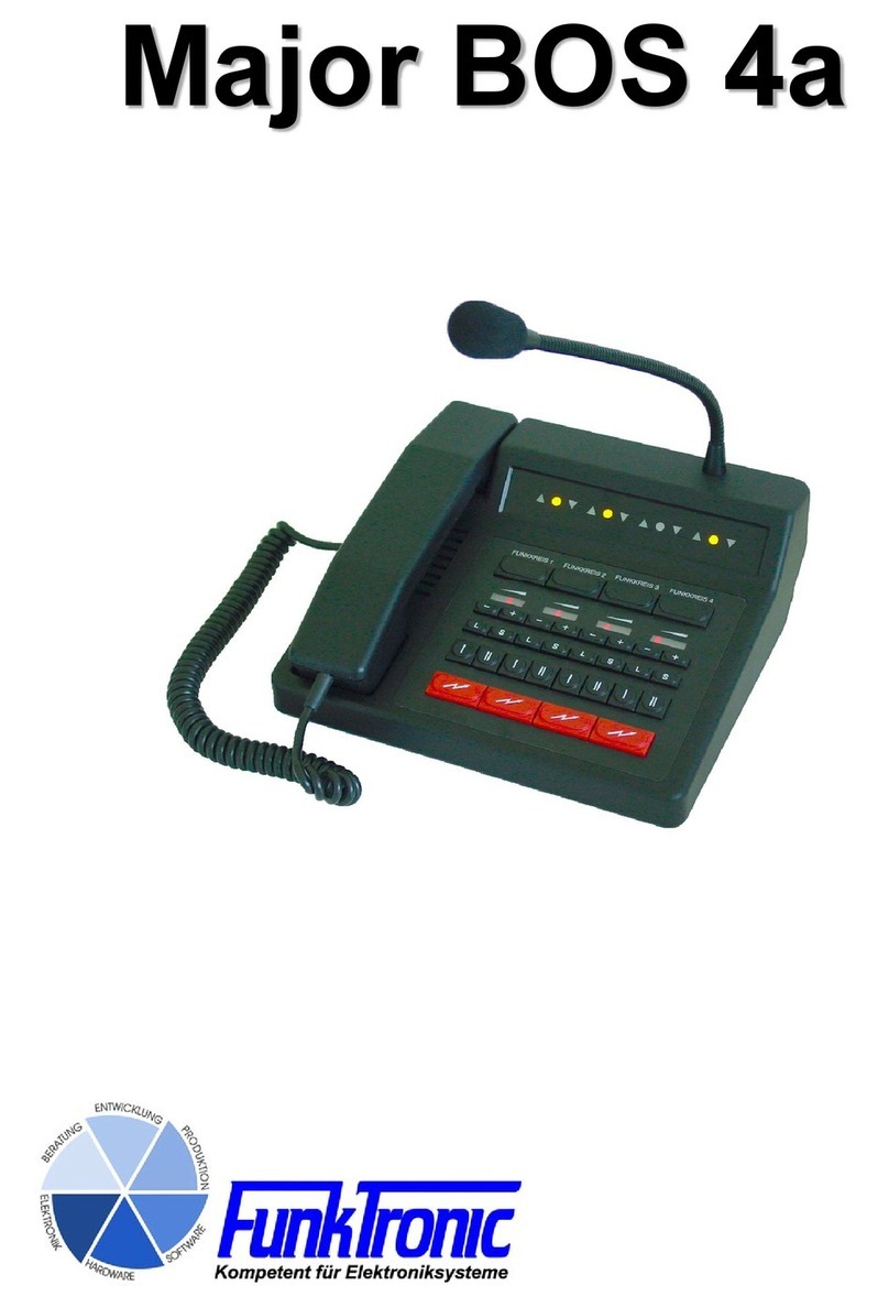
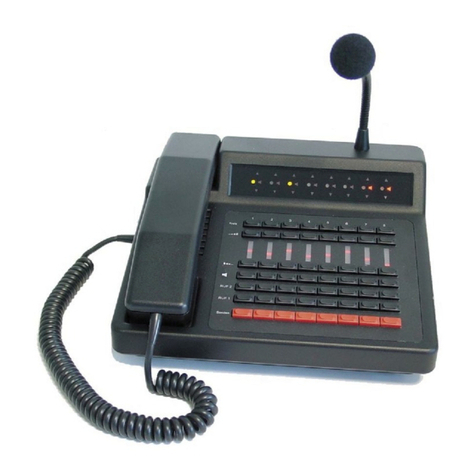
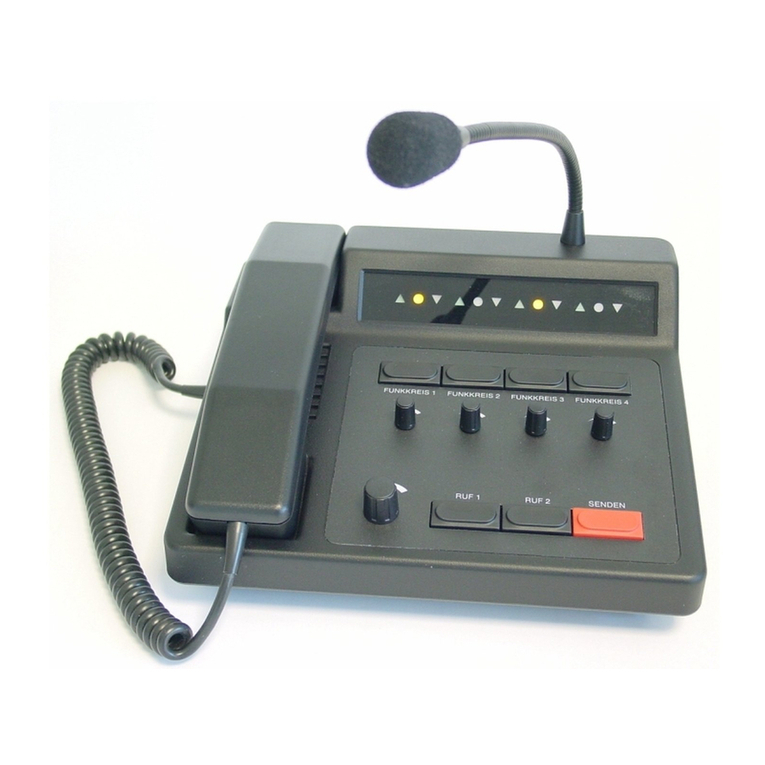
FunkTronic Major BOS V Series User manual

Major BOS V(oIP)
Major BOS 1V
Major BOS 8V
Major BOS 4V

- 2 - mbosv_eng (25.02.2014)
mbosv_eng (25.02.2014) - 3 -
Contents
Connectivity 3
Major BOS 1V/4V/8V 3
Control and Display Elements 4
Layout - Major BOS 4V 5
Layout - Major BOS 8V 6
Calling Radio Channels 7
Encoder 8
Transmitter Control 8
Connection to Telephone AF 8
Microphone Selection 8
Opto-Coupler Input 9
Functions for TETRA Digital Radios 9
Configuration via the Web Interface 10
The Web Interface 11
The System Pages 12
The Application Pages 14
RS232 Monitor 17
Sockets Pinout 18
Technical Data 19
General Safety Remarks 20
Returning of Old Equipment 20

- 2 - mbosv_eng (25.02.2014)
mbosv_eng (25.02.2014) - 3 -
Major BOS 1V/4V/8V
Major BOS 1V, Major BOS 4V and Major BOS 8V are µC-controlled desktop controller
units for 2-way radio systems controlling one, up to four or eight radios, respectively.
The connection to the radios is achieved over one single ethernet connection (LAN
or via Internet) instead of separate cables for each radio circuit. The device can be
configured via its web interface using any PC that is connected to the same IP network.
For this, you can use an ordinary web browser (e.g. Firefox or Internet Explorer).
For operation a 12 V DC power supply is necessary. Alternatively, the Major can also be
ordered with the option Power-over-Ethernet (PoE), that allows power supply via the
ethernet socket (ETH).
A Major BOS 1V can control one, a Major BOS 4V can manage up to 4, a Major BOS
8V up to 8 channels (radio sets, PA systems -/intercom etc.) via their ethernet interfaces.
Furthermore, an external handset/headset, an external signalling device and a tape
recorder. Furthermore there is a RS232-connection, to which a terminal or PC can be
connected.
Connectivity
12VDC -> power supply connector (12V DC, external, max. 1.5A)
TB (ST7) -> tape recorder
RS232 (ST6) -> RS 232 connection
PTT (ST5) -> PTT (e.g. foot switch)
HS (ST4) -> headset
S/E (ST3) -> no function
ETH (ST1) -> ethernet interface
see also section Sockets Pinout

- 4 - mbosv_eng (25.02.2014)
mbosv_eng (25.02.2014) - 5 -
Control and Display Elements
Keyboard
The keyboard holds the following functions for each of the four/eight channels:
Button Function (standard)
(Funk-)kreis x selection button
VOL+ increase volume
VOL-
decrease volume
L / mute loudspeaker
S special function (not assigned, only MBOS 4V)
I / RUF1 button for tone call 1
II / RUF2 button for tone call 2
/ Senden PTT button
All buttons can be disabled separately. For Major BOS 1V, channel selection and loudspeaker
buttons are not necessary. The volume is adjusted by a potentiometer knob.
Carrier Display
For each of the four/eight circuits there is a separate carrier display (squelch) LED , that
is activated/deactivated using data telegrams.
PTT Display
For each of the eight circuits there is also a separate PTT display LED , that lights if the
transmitter for the respective circuit is keyed by pressing PTT, call 1 or call 2. (If a PTT
display flashes, another control set is transmitting on this radio circuit.)
Selection Display
The selection display LED lights, if the respective circuit was selected and is active. A
flashing selection display LED indicates that the Major is currently trying to establish the
connection via ethernet.
Loudspeaker / Volume Display (not for Major BOS 1V)
The volume display (separately for each channel) is an LED chain and indicates the current
volume. If the the loudspeaker is switched off, all LEDs of the chain are dark for Major
BOS 4V. The Major BOS 8V has a separate loudspeaker LED that displays the status of
the loudspeaker.

- 4 - mbosv_eng (25.02.2014)
mbosv_eng (25.02.2014) - 5 -
Layout - Major BOS 4V
1
4
5
6
8
7
9
2
3
10
11
1 - Transmiting- , Squelch- , Selection Status LED
2 - Channel Selection Buttons
3 - Volume Display (row of LEDs)
4 - Volume Control Buttons (+/
-
)
5 - Loudspeaker Buttons (mute)
6 - Special Function Buttons
7 - Encoder Buttons (I/II)
8 - PTT (for gooseneck or headset microphone)
9 - Loudspeaker
10 - PTT Button (for handset)
11 - Handset
12 - Gooseneck Microphone

- 6 - mbosv_eng (25.02.2014)
mbosv_eng (25.02.2014) - 7 -
Layout - Major BOS 8V
4
5
6
87
9
2
3
10
11
1
12
1 - PTT , carrier , loudspeaker and selection displays
2 - selection buttons
3 - volume buttons (increase)
4 - volume displays (LED line)
5 - volume buttons (decrease)
6 - loudspeaker buttons (mute)
7 - call 1 buttons
8 - call 2 buttons
9 - PTT buttons (for gooseneck microphone)
10 - loudspeaker
11 - handset with PTT button
12 - gooseneck microphone

- 6 - mbosv_eng (25.02.2014)
mbosv_eng (25.02.2014) - 7 -
Calling Radio Channels
Channel Selection
To activate one of the different channels push the corresponding selection button. To
deactivate a channel again push the corresponding selection button once more.
Depending on the configuration (see also: Configuration via the Web Interface) you
can either select several channels simultaneously or only one channel at a time. The
status of the loudspeaker can be set accordingly.
The channel selection display LED is illuminated if the channel is selected.
The channel selection at power-on can be configured via the Web Interface. The channel
selection during the last operation can also be saved for the next power-on.
Communicating with the Radio Subscriber
There are three different ways of talking to a radio subscriber:
a) By pushing one of the red PTT buttons the transmitter of the corresponding channel
is activated via a TCP telegram (PTT display LED lights up) and you can talk to the
caller through the gooseneck microphone. (It is also possible to connect an external switch
contact instead of a PTT button. See section Opto-Coupler input.) After pressing the
PTT button the caller can be heard on the loudspeaker. The receiver volume of the cor-
responding channel is adjustable.
b) By picking up the handset and pushing the PTT button on the inside of the handset. By
doing so the transmitter of the selected channel is activated (PTT LED lights up) and
you can talk with the caller through the microphone of the handset.
Depending on the configuration you can hear the caller constantly on the handset or only
after deactivating the PTT button. The call is ended by replacing the handset. The volume
of the earpiece and the microphone are each adjustable via the Web Interface.
c) By connecting a compatible headset and pressing the corresponding PTT button PTT2
(e.g. a foot switch). By doing this the transmitter of the selected radio channel is also
turned on (PTT LED lights up) and you can talk with the caller through the microphone
of the headset.
Depending on the configuration you can hear the caller constantly on the headset or only
after releasing the PTT button. The volume of the corresponding channel is adjustable.
The level settings for microphone, loudspeaker etc. can also be configured via the Web
interface.

- 8 - mbosv_eng (25.02.2014)
mbosv_eng (25.02.2014) - 9 -
Encoder
Major BOS V has an integrated encoder for call 1 and call 2. The calls for each channel
are transmitted directly with the corresponding buttons on the keyboard (I / RUF 1 or I /
RUF 2). The calls are transmitted as long as the corresponding button is being pressed.
Transmitter Control
The transmitters of the selected radio channels are activated with one of the PTT but-
tons (e.g. handset or headset) and stay activated as long as the PTT button is being
pressed. During transmission of call 1/2 the corresponding transmitters are automatically
activated.
It is always possible to transmit on non-activated radio channels by using the red PTT
buttons on the control panel. The assignments of the buttons to the channels can also be
customized (Web Interface).
Connection to Telephone AF
The audio-frequency connection is not integrated in the Major BOS V anymore. But by
connecting the external headset-adapter the headset can be used as a combined com-
municating device for telephone and radio.
The headset is switched to the telephone by an opto-coupler input, which has to be
configured accordingly.
Microphone Selection
For each of the 3 PTT inputs it is possible to program the corresponding microphone
individually via the Web Interface.
Additionally there are two ways of automatic headset detection:
- the Major BOS 8a can detect if a headset is connected by measuring the headset
supply voltage (see Web interface).
- one of the inputs can be configured as headset detection (headset is connected if
input is activated, i.e. connected to GND)
If the Major BOS 4a has detected a headset then all buttons programmed as SH/HS-
PTT use the headset microphone. Otherwise they use the gooseneck microphone.

- 8 - mbosv_eng (25.02.2014)
mbosv_eng (25.02.2014) - 9 -
Opto-Coupler Input
The opto-coupler input on ST5 can be configured via Web interface to fulfill different
tasks in the same way as all inputs can be.
To activate the opto-coupler input, a direct current (3V < U < 15V) is necessary that can
be obtained directly from ST14a/2. For higher ext. switching voltages an additional external
dropping resistor is necessary (internal dropping resistor = 1kohm).
Functions for TETRA Digital Radios
Using TETRA, speaking is not possible until the conversation is initiated. Therefor, the
radio transmits an attention tone. Usually, this tone cannot be heard in the loudspeaker
as it is muted when transmitting. Hence, the PTT button must be configured so that the
loudspeaker is not muted when it is pressed.

- 10 - mbosv_eng (25.02.2014)
mbosv_eng (25.02.2014) - 11 -
Configuration via the Web Interface
Preparing the PC
To be able to acces the Web Interface of the Major BOS V, a PC has to be configured
properly. Ex factory, the network address of the Major is as follows:
IP address: 192.168.16.181
Subnet mask: 255.255.255.0
The configuration of the network settings works similarly under Windows XP, Vista, 7 and
8. The following examples are for Win7. If you encounter any network problems, you might
have to contact your local network administrator. If you do not know the IP address of your
Major you can start it in "Default IP-Mode" (Major has the IP address as set ex factory).
Therefor, press the PTT button of channel 1 and the PTT button on the inside of the handset
while leaving the handset hung-up and switch on the Major (connect to power).
Open Control Panel (via the "Start" menu) and choose "View network status and tasks"
(via "Network and Internet"). On the following screen (see image above) click on "LAN
connection" (underlined red). On the next screen "LAN connection status", click on
"Properties" (you need administrator rights here), to get to the window "Properties of LAN
connection". Choose "TCP/IP(v4)" and again click on "Properties".
On screen "Properties of TCP/IP(v4)" choose "Advanced..." and click "Add..." in the IP

- 10 - mbosv_eng (25.02.2014)
mbosv_eng (25.02.2014) - 11 -
adress area. In the appearing input screen (see image below) the first three numbers of
the IP address must be chosen analogously to the Major's address. As each IP may only
appear once in a given network, the fourth number must be different from the Major's (0-
254, not 181). The subnet mask is set to 255.255.255.0 as for the Major. Confirm your
input with "Add" and close all previously opened screens with "OK" or "Close".
In case the first 3 numbers of your PC's standard IP address are already 192.168.16, you
can skip the previous steps, but you have to take care that no other device with the IP
181 (4th number) is connected to the network during configuration. In more sophisticated
network architectures the range 192.168.16 could also be already used in another network
segment.
This kind of problems can be completely avoided if Major and PC are connected to a to a
separate network hub or switch, which is solely used for that purpose.
Example Configurations of Funktronic devices in different network architectures can be
found in the manual: "Ethernet Connections".
The Web Interface
Currently, the Web Interface is only available in German, but the following pages should
simplify its use.
To start the Web Interface, open a HTML browser (e.g. Mozilla Firefox, Internet Explorer)
and enter the Major's IP: (ex factory:) 192.168.16.181
You are prompted for authentification. Factory defaults are:
User Name (Benutzername): mbosv
Passwort: radio
The main menu in the title bar (see image on next page) contains the items "System",
"Applikation", "Reboot" and "Update". The System pages mainly contain the network
configuration and the possibility to change the authentification information. All further
paramaters are configured on the Application pages. The button Reboot executes a
restart, including a reset to factory defaults if desired. The button Update can be used to
update the network component's software.
Additionally the title bar shows some basic data of the device and the software.

- 12 - mbosv_eng (25.02.2014)
mbosv_eng (25.02.2014) - 13 -
The System Pages
After entering the Major's IP address into the adress bar of the browser, system page 1
is displayed (see image above). This page contains the local network settings of the
Major BOS V. Als Startseite wird die System-Seite 1 geöffnet (siehe oben). In order to
have effect, any configuration changes need to be confirmed with "Anwenden". Thereupon
the Major restarts using the new parameters.
Status
Shows the connetion status of each radio channel (red: channel active, but no connection
to the remote station, green: channel active and connected, white: channel deactivated)
Host-Name
Name of the Major in the local network.
Lokale IP-Adresse
If the IP adress is highlighted in orange, the device was started in Default IP Mode. Here,
the default IP address is restored, to assure access even if the IP adress is unknown.
This operation mode is achieved by pressing the PTT button of the hung-up handset and
the PTT of channel 1 simultaneously at power-on. All LEDs are flashing.
Default: „192.168.16.190“

- 12 - mbosv_eng (25.02.2014)
mbosv_eng (25.02.2014) - 13 -
Netzmaske
Subnet mask, as is used in the local network.
Default: „255.255.255.0“
Gateway IP-Adresse
The address of the router/DSL gateway in the local network. This is necessary, if the remote
stations are not part of the same network.
Default: „0.0.0.0“
Primärer DNS-Server
A DNS server is only necessary if host/DNS names are used. For the use of IP addresses,
only, no information has to be made.
Default: „0.0.0.0“
Alternativer DNS-Server
If host/DNS names are used, a secondary DNS server should exist in case the primary
DNS server is currently not available.
Default: „0.0.0.0“
Jitter Buffer Delay
Compensates for deviations in the transfer time of the audio packets. The higher this value
is, the better cracks and interruptions are avoided. However, the voice delay is increased
by the jitter buffer delay.
Default: „80 ms“
Web Server Port
The port on which the web server of the device is listening.
Default: „80“
LS Port
Via this port controlling the device by an external software is achieved. For that purpose,
the Major BOS V is listening on the TCP port defined here.
Default: „9999“
Debug/Syslog
Here, the amount of syslog messages, that is displayed on the system page "Info", is
configured.
On system page 2 you can find the network settings of the remote stations (radio
channels). On this page, changes for one radio channel must be always confirmed with
"Anwenden" before continuing the changes for the next one. For each single channel, the
following settings exist:
Status
A channel can be active ore deactivated. For active channels the Major tries connecting to
the respective remote station. As long as no connection is established the channel LEDs
are flashing. If the channel is deactivated, no connection is established and the channel
cannot be used.
Kreisbündel
Channel bundles are necessary to operate both channels of an (old) FT636 IP Interface. For
this purpose, two neighboring radio channels must be combined to a channel bundle.
Ziel DNS Name
The target DNS name can be used instead of the IP address. In this case, one has to pay
attention that at all times at least one DNS server is operating and can be accessed.

- 14 - mbosv_eng (25.02.2014)
mbosv_eng (25.02.2014) - 15 -
Ziel IP Adresse
The IP addresses of the remote stations must all be different (also different from the own
IP address).
Port für Audio/NF
The audio port is used for transmission of the audio packets. The used UDP protocol must
be activated in firewalls. All ports must be different from each other.
Port für Signalisierung
The signalling port is used to transmit control telegrams (PTT, Squelch). The used TCP
protocol must be activated in firewalls. All ports must be different from each other.
On system page 3 you can change the user name and the password. Before this page
opens you are prompted once more to enter the current password.
The system page Info is used to diagnose the network connections. No settings can be
changed in this page.
Verbindungsstatus
Informations on the connection status are displayed for one radio channel. The desired
channel can be sleceted using the + / - buttons.
Debug und Syslogmeldungen
Here, you can see the 20 most recent syslog messages. These are broadcasted throughout
the ethernet. For diagnosis they can be recorded by a suitable tool (Syslog Server,
Wireshark, TCP-Dump).
The Application Pages
Application page 1 allows to configure the common parameters of operation of the Major
BOS V. As well as for the system pages, any configuration changes need to be confirmed
with "Anwenden", in order to have effect.
Codec
The audio codec must be chosen accordingly to that of the remote station. As the FT636
IP Interface uses A-law, this codec has to be used for this kind of remote station.
TX-LED
Here you can define if the transmission LED is lit immediately or after the acknowledgement
of the remote station is received.
RS232 Ausgaben
Here you can define which informations are available via the RS232 interface.
Wiederholzeit Vol +/- Tasten
Defines the duration of pressing the button after which the volume is increased/decreased
once more. This time can be configured for the first as well as for further repetitions
separately.
Headseterkennung
Automatic headset detection can be configured via the button „Schwellwert einstellen“. A
new screen opens that leads through the process.
Ein-/ Ausgänge
For pins that can be used as inputs or outputs, the direction of information can be chosen
here.

- 14 - mbosv_eng (25.02.2014)
mbosv_eng (25.02.2014) - 15 -
Funktion der Eingänge / Funktion der Ausgänge
The possible functions of inputs and outputs can be freely assigned to the respective pins.
For PTT inputs, the assignment to the desired microphones is also made here.
Eingangsverstärkung / Ausgangsverstärkung
If necessary, the different AF input and output levels can be adjusted here.
Mikrofonausgabepegel / Ausgabepegel Ruf
The output levels of the microphone and of call 1/2 can also be adjusted separately for
the different AF directions.
Application page 2 contains the channel-specific parameters as well as the volume
settings.
Using "+" / "-" you can browse through the different radio channels. For each channel
the following parameters can be altered:
Funkkreiszusstand speichern
Remember the last channel selection status for the next power-on.
Funkkreis beim Einschalten
Channel is always on or always off at power-on (overwrites the previous setting).
Lautsprecherzustand speichern
Remember the last channel selection status for the next power-on.
Lautsprecherzustand beim Einschalten
Loudspeaker is always on or always off at power-on (overwrites the previous setting).
Lautstärke speichern
Remember the last volume setting for the next power-on.
Lautstärke beim Einschalten
Set defined volume level at power-on (overwrites the previous setting).
The following Parameters can be altered separately for each AF direction (hand set,
headset, Loudspeaker 1, Loudspeaker 2, tape output, S/E output):
Min. Lautstärke
Lowest volume level, that is possible.
Max. Lautstärke
Highest volume level, that is possible.
Max. Lautstärke Kreis aus
Highest volume level, if the channel is not selected.
Max. Lautstärke Kreis an
Highest volume level, if the channel is selected.
Max. Lautstärke Sender aus
Highest volume level, if the transmitter is off.
Max. Lautstärke Sender anderer Kreis an
Highest volume level, if the transmitter of another channel is on.
Max. Lautstärke LS aus
Highest volume level, if the loudspeaker is off.
Max. Lautstärke LS an
Highest volume level, if the loudspeaker is on.

- 16 - mbosv_eng (25.02.2014)
mbosv_eng (25.02.2014) - 17 -
Max. Lautstärke Hörer on Hook
Highest volume level, if the handset is hung up.
Max. Lautstärke Hörer off Hook
Highest volume level, if the handset is taken.
Max. Lautstärke Sender an
Highest volume level, if the transmitter is active.
Max. Lautstärke Sender eigener Kreis an
Highest volume level, if the transmitter of the own is active.
On application page 3 you can define the functions of the buttons. For each button one
function for short pressing and one for long pressing can be programmed.
On application page Manuell you are able to directly change the programming of the
underlying registers. This page is mainly for settings of non-standard software, that are
not implemented into the web interface.

- 16 - mbosv_eng (25.02.2014)
mbosv_eng (25.02.2014) - 17 -
RS232 Monitor
For via the RS232 interface the respective socket of the Major needs to be connected to
the PC's COM port. In case your PC does not have a COM socket, you can also use a
COM-USB converter. In order to read the syslog messages, you need to use a terminal
software (e.g. Hyper Terminal, H-Term...) .
The pins of both sockets must be connected in the following way:
RS232 (ST6) Function 9pin COM of PC
1 TxD 2
2 RxD 3
3 GND 5

Sockets Pinout
All sockets of the Major shown from rear view.
Layout Power
PWR
12 VDC, max 1,5 A,
inside: + , outside: GND
Layout RS 232
ST6
TXD (RS232) 1
RXD (RS232) 2
GND 3
IN/OUT 1 4
IN/OUT 2 5
IN/OUT 3 6
AF out Loudspeaker 2 (LS2 +) 7
AF out LS2: GND (LS2
-
) 8
Ethernet Socket ETH
ST1
Layout PTT
ST5
PTT input (PTT HS2, to GND) 1
+batt. output., supply voltage 2
for headset-headset switching PCB
control pin 3
for headset-headset switching PCB
opto-coupler input (anode +) 4
opto-coupler Input (cathode -) 5
GND (PTT HS2 ground) 6
Layout HS Headset
ST4
PTT input HS (PTT HS1, to GND) 1
AF input HS (micro +) 2
AF output HS (headset +) 3
AF output HS-GND (headset -) 4
AF input HS-GND (micro -)
5
GND (PTT HS1 ground) 6
ST7 ST5ST6PWR
ST1
ST4
ST3
Layout TB Tape
ST7
GND (ground) 1
audio tape switching contact 2
AF output A (mod. +) 3
AF output B (mod.
-
) 4
The AF output A-B is equipped with a transformer and
hence potential-free.
Two connectors for headsets are available. A headset
can be connected to ST14. An external PTT button (e.g.
foot switch) can be connected to ST14A.
Layout S/E
ST3
AF input (+) 1
AF input (
-
) 2
input w. pullup (SQL S/E) 3
GND 4
+batt (12V DC) 5
(do not connect to radio!)
PTT S/E (IN/OUT) 6
AF output (Mod +) 7
AF output (Mod
-
) 8
The AF in/outputs are equipped with transformers
and hence potential-free.
TX+ 1
TX- 2
RX+ 3
RX- 6
The connection to the ethernet is achieved using
the standard 8-pin patch cables.

Technical Data
Supply
Voltage +12VDC -15% +25%
Current Consumption ca. 160-400 mA
Input Level (S/E)
Factory setting 775 mV (= 0 dB) / 600Ohm
Adjustment range -99 dB to +26 dB
Input impedance 600 Ohm
Output Level (S/E)
Factory setting 500 mV (= - 3,8 dB) / 200 Ohm
Adjustment range -99 dB to +26 dB / 200 Ohm
Ausgangsimpedanz ca. 200 Ohm
Output Level for Earphone (headset) (RX-Out)
Factory setting 0 dB (at 200 Ohm)
Adjustment range -99 dB bis +26 dB (at 200 Ohm)
Output impedance ca. 150 Ohm
Input Level for Mikrophone (headset) (TX-In, electret)
Factory setting 0 dB
Adjustment range -99 dB bis +26 dB
Output impedance ca. 700 Ohm
Weight ca. 1500 g
Dimensions (without gooseneck microphone)
width x depth x height 245 x 220 x 90 mm

- 20 - mbosv_eng (25.02.2014)
mbosv_eng (25.02.2014) - 21 -
Please read the operating instructions carefully before installation and setup.
The relevant regulations must be complied to when working with 230V line voltage, two-wire-
lines, four-wire-lines and ISDN-lines. It is also very important to comply to the regulations
and safety instructions of working with radio installations.
Please comply to the following safety rules:
- All components may only be mounted and maintained when power is off.
- The modules may only be activated if they are built in a housing and are scoop-proof.
- Devices which are operated with external voltage - especially mains voltage - may only
be opened when they have been disconnected from the voltage source or mains.
- All connecting cables of the electronic devices must be checked for damage regularly
and must be exchanged if damaged.
- Absolutely comply to the regular inspections required by law according to VDE 0701
and 0702 for line-operated devices.
- Tools must not be used near or directly at concealed or visible power lines and conductor
paths and also not at and in devices using external voltage – especially mains voltage -
as long as the power supply voltage has not been turned off and all capacitors have been
discharged. Electrolytic capacitors can be still charged for a long time after turning off.
- When using components, modules, devices or circuits and equipment the threshold
values of voltage, current and power consumption specified in the technical data must
absolutely be complied to. Exceeding these threshold values (even if only briefly) can
lead to significant damage.
- The devices, components or circuits described in this manual are only adapted for the
specified usage. If you are not sure about the purpose of the product, please ask your
specialized dealer.
- The installation and setup have to be carried out by professional personnel.
Returning of Old Equipment
According to German law concerning electronic devices old devices cannot be disposed off
as regular waste. Our devices are classified for commercial use only. According to § 11 of
our general terms of payment and delivery, as of November 2005, the purchasers or users
are obliged to return old equipment produced by us free of cost. FunkTronic GmbH will
dispose of this old equipment at its own expense according to regulations.
Please send old equipment for disposal to: FunkTronic GmbH
Breitwiesenstraße 4
36381 Schlüchtern
GERMANY
>>> Important hint: freight forward deliveries cannot be accepted by us.
February 2nd , 2006
Subject to change, Errors excepted!
General Safety Remarks
This manual suits for next models
3
Table of contents
Other FunkTronic Controllers manuals