Carel HEOS BOX R744 User manual

Integrated Control Solutions & Energy Savings
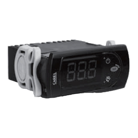
NO POWER
& SIGNAL
CABLES
TOGETHER
READ CAREFULLY IN THE TEXT!
HEOS BOX R744
User manual
Assembly instructions, including
user and maintenance information
CE version


3
ENG
Heos BOX R704 +0300140EN - rel. 1.0 - 25.05.2022
Contents
1. WARNINGS 5
1.1 General warnings..............................................................................................5
2. GENERAL FEATURES AND SCOPE OF
THE SUPPLY 7
2.1 Description of HEOS BOX.............................................................................7
2.2 Single and multi-evaporator congurations with .........................
HEOS BOX R744 .................................................................................................7
2.3 Heosbox models and valve selection...................................................7
2.4 Accessories available.......................................................................................8
2.5 Connection diagrams: local and supervisor connection .........8
2.6 Technical data ..................................................................................................10
2.7 Operating limits ..............................................................................................10
2.8 Electrical specications of the auxiliary loads ..............................11
2.9 Dimensions and weights...........................................................................11
2.10 Refrigerant circuit...........................................................................................12
2.11 Electrical panel.................................................................................................13
2.12 Requirements for positioning the unit and .......................................
multi-evaporator layout.............................................................................14
3. HANDLING 19
3.1 Opening the packaging.............................................................................19
3.2 Positioning the unit......................................................................................19
4. INSTALLATION 21
4.1 Material supplied............................................................................................21
4.2 Water connections........................................................................................21
4.3 Feedwater specications...........................................................................22
4.4 Refrigerant connections ............................................................................22
4.5 Electrical connections .................................................................................23
4.6 Kit installation...................................................................................................24
4.7 Refrigerant charging procedure...........................................................24
4.8 Oil top-up requirements............................................................................25
4.9 Refrigerant discharging procedure ....................................................26
4.10 Commissioning checklist ..........................................................................26
5. MAINTENANCE 27
5.1 Routine maintenance..................................................................................27
5.2 One-o service and spare parts list....................................................27
6. ACCESSORY KIT INSTALLATION 28
6.1 Secondary multi-evaporator panel.....................................................28
6.2 WiFi gateway kit..............................................................................................29
6.3 Anti-sweat heater kit....................................................................................29


5
ENG
Heos BOX R704 +0300140EN - rel. 1.0 - 25.05.2022
1. WARNINGS
1.1 General warnings
This document is the set of original instructions written in Italian; all other
languages have been professionally translated. For the intended meaning
reference must always be made to the original Italian version.
The HEOS BOX units are water-cooled condensing units for indoor
use, intended for medium (MT) and low temperature (LT) commercial
refrigeration applications. HEOS BOX is a partly-completed machine and
as such must be appropriately connected to an evaporating system in
order to function correctly. HEOS BOX and the evaporating unit together
comprise the complete equipment. Carefully read this booklet and all
documentation supplied with the unit. This documentation must be kept
by the customer (manufacturer, designer, installer or owner of the nal
equipment) for any future maintenance or service. The warranty will be
void if the instructions described under “Warnings”are not complied with.
The operation of HEOS BOX is specied in the technical
documentation supplied with the product or can be
downloaded, even prior to purchase, from the website
www.carel.com.
Every product supplied by CAREL Industries, in relation to its advanced
level of technology, requires setup/conguration/programming to be
able to operate in the best possible way for the specic application. Failure
to complete such operations, which are required/indicated in the user
manual, may cause the nal product to malfunction; CAREL Industries
accepts no liability in such cases. The customer (manufacturer, developer,
installer or owner of the nal equipment) accepts all liability and risk
relating to the conguration of the product in order to reach the expected
results in relation to the specic nal installation and/or equipment. CAREL
Industries may, based on specic agreements, act as a consultant for the
installation/commissioning/use of the unit, however in no case does it
accept liability for the correct operation of the unit and the overall system
if the warnings or suggestions provided in this manual or in other product
technical documents are not heeded. In particular, as well as observing
the above warnings and suggestions, the following warnings must be
observed for correct use of the product:
ELECTRIC SHOCK HAZARD
The unit contains live electrical components. Disconnect the mains
power supply before accessing inside parts or during maintenance and
installation. It is forbidden to remove the access panels to the internal
parts of the unit without rst having placed disconnect switch QS1 and
the switch or disconnect device on the HEOS BOX power supply line in the
OFF position (see the wiring diagram). The mains power disconnect device
must have a contact opening distance that allows complete disconnection
in overvoltage category III conditions; it must also be incorporated into the
HEOS BOX power supply line in accordance with national regulations.
WATER LEAK HAZARD
The unit comprises components containing water or water with antifreeze
additive (generally glycol). Malfunctions in the unit’s connections or to its
operation may cause uid leakages. Avoid direct contact of the uid with
the eyes/skin and, in the event of accidental contact or inhalation, seek
medical advice.
PRESSURE EQUIPMENT HAZARD
The unit is supplied sealed with an inert gas (nitrogen) pre-charge of
around 1 bar (14.5 psi) above atmospheric pressure. Take all necessary
precautions to avoid material from being expelled outside of the unit
when venting the gas. Before charging the unit with R744 refrigerant, make
sure that all the activities described in the “Introduction”, “Handling” and
“Installation” chapters have been completed, including connection of the
high pressure safety valve discharge to suitable piping, so as to discharge
excess pressure safely away from the equipment. Carefully verify the PS
and TS after having incorporated the HEOS BOX into the evaporating
system, considering all the components of the refrigerant circuit (for the
refrigerant circuit contained inside HEOS BOX, refer to the values shown
on the unit’s label and reported in this manual). Always wear protective
glasses when performing any work on the unit.
BURN HAZARD
The unit contains components that may reach high temperatures. Take all
necessary protective measures before performing any operations on the
unit.
WARNINGS
• HEOS BOX product is a component that can be integrated into various
dierent applications. HEOS BOX installation requires the installer to
ensure suitable protection against direct contact with hazardous high
voltage parts. Under no circumstances should any live parts be accessed.
• The installation of the product must include a compliant earth
connection, using the yellow-green terminal provided inside the
electrical panel.
• Environmental and power supply conditions must conform to the
values specied on the product rating labels.
• Handling, installation, use and maintenance must be performed by
qualied personnel who have the qualications and authorisations
required by local regulations, using appropriate personal protective
equipment (PPE), who are aware of the necessary precautions and who
are able to correctly and safely complete all required operations.
• All operations on the product must be carried out according to the
instructions provided in this manual and on the labels applied to the
product. Any uses or modications that are not authorised by the
manufacturer are considered improper. CAREL Industries S.p.A. declines
all liability for any such unauthorised use.
• Keep all ventilation openings on the equipment’s enclosure or on the
structure for built-in installation clear of obstructions;
• Do not damage the refrigerant circuit
• Do not attempt to open the unit in any way other than described in
the manual.
• Observe the standards in force in the place where the unit is installed.
• Keep the unit out of the reach of children and animals. The unit must be
operated/serviced/cleaned by qualied adult personnel. The operations
described above are therefore prohibited to minors or people with
reduced psychophysical abilities.
• Do not install and use the product near objects that may be damaged
when in contact with water (or condensate). CAREL Industries S.p.A.
declines all liability for direct or indirect damage following water leaks
from the unit.
• Do not use corrosive chemicals, solvents or aggressive detergents
to clean the inside and outside parts of the unit, unless specically
indicated in the user manual.
• Do not drop, hit or shake the unit, as the inside parts and the linings may
be irreparably damaged.
• If the unit is delivered arranged in a way other than that required for
installation (upside down or on one side), wait at least 24 hours before
starting it the rst time.
6
ENG
Heos BOX R704 +0300140EN - rel. 1.0 - 25.05.2022
• HEOS BOX is specically designed to be connected to evaporator coils
with air as the secondary uid, placed inside a refrigerated showcase or
cold room. Connection to other types of evaporators may compromise
safety, cause malfunctions and aect the performance of the unit;
CAREL Industries declines all liability for damage consequent to or
caused directly by connection to such evaporators.
• Heos Box is intended for use in commercial, professional or industrial
activities, and not for sale to the public.
• Caution: Heos Box is not intended for use in residential locations, and
cannot guarantee adequate protection for radio reception in such
locations.
CAREL Industries adopts a policy of continual development. Consequently,
CAREL Industries reserves the right to make changes and improvements
to any product described in this document without prior warning. The
technical specications shown in the manual may be changed without
prior warning. The liability of CAREL Industries S.p.A. in relation to its
products is specied in the CAREL Industries S.p.A. general contract
conditions, published on the website www.carel.com and/or by specic
agreements with customers; specically, to the extent where allowed by
applicable legislation, in no case will CAREL Industries S.p.A., its employees
or subsidiaries/aliates be liable for any lost earnings or sales, losses of data
and information, costs of replacement goods or services, damage to things
or people, downtime or any direct, indirect, incidental, actual, punitive,
exemplary, special or consequential damage of any kind whatsoever,
whether contractual, extra-contractual or due to negligence, or any other
liabilities deriving from the installation or use of the product, even if CAREL
Industries or its subsidiaries/aliates are warned of the possibility of such
damage.
DISPOSAL: INFORMATION FOR USERS
Fig. 1 Fig.2
PLEASE READ AND KEEP
With reference to European Union directive 2012/19/EU issued on 4 July 2012
and related national legislation, please note that:
1. Waste Electrical and Electronic Equipment (WEEE) cannot be disposed of as
municipal waste but must be collected separately so as to allow subsequent
recycling, treatment or disposal, as required by law;
2. users are required to take Electrical and Electronic Equipment (EEE) at end-
of-life, complete with all essential components, to the WEEE collection
centres identied by local authorities. The directive also provides for the
possibility to return the equipment to the distributor or retailer at end-of-life
if purchasing equivalent new equipment, on a one-to-one basis, or one-to-
zero for equipment less than 25 cm on their longest side;
3. the equipment may contain hazardous substances: the improper use or
incorrect disposal of such may have negative eects on human health and
on the environment;
4. the symbol (crossed-out wheeled bin, see Figure 1), is shown on the product
or on the packaging, indicates that the equipment must be disposed of
separately at end-of-life;
5. if at end-of-life the EEE contains a battery (Figure 2), this must be removed
following the instructions provided in the user manual before disposing
of the equipment. Used batteries must be taken to appropriate waste
collection centres as required by local regulations;
6. in the event of illegal disposal of electrical and electronic waste, the
penalties are specied by local waste disposal legislation.
NO POWER
& SIGNAL
CABLES
TOGETHER
READ CAREFULLY IN THE TEXT!
Separate as much as possible the probe and digital input cables from
cables to inductive loads and power cables, so as to avoid possible
electromagnetic disturbance. Never run power cables (including the
electrical panel cables) and signal cables in the same conduits.
IMPORTANT WARNINGS
This product is to be integrated and/or incorporated into the nal
apparatus or equipment. Verication of conformity to the laws and
technical standards in force in the country where the nal apparatus or
equipment will be operated is the manufacturer’s responsibility.Before
delivering the product, Carel has already completed the checks and
tests required by the relevant European directives and harmonised
standards, using a typical test setup, which however cannot be
considered as representing all possible conditions of the nal
installation.
DECLARATION OF CONFORMITY
HEOS BOX complies with the following directives in force:
Directive Standard
HB200C0300CE0
HB200C0400CE0
HB200C0600CE0
HB200C1000CE0
2006/42/EC
for all
machinery
EN 60335-2-89:2010 in
combination with
EN 60335-1:2012
X X X X
2014/30/EE
(EMC)
EN 61000-6-3:2021 X X
EN 61000-6-8:2021(1)(2) X X
Notice:
(1) installation and maintenance of Heos Box must be performed by profession-
al personnel, with sucient knowledge to adopt the EMC mitigation measures
described in the instructions;
(2) if Heos Box is installed less than 30 m from residential environments, the
professional installer must evaluate the EMC conditions before installation, as
required by the reference standard.
WARRANTY ON MATERIALS
See the document “Warranty terms and conditions”, which should
be kept carefully together with this manual and all other technical
documentation delivered with the HEOS BOX unit.
APPROVAL
The quality and safety of CAREL Industries S.p.A. HQ products are
guaranteed by the ISO 9001 certied design and production system.

7
ENG
Heos BOX R704 +0300140EN - rel. 1.0 - 25.05.2022
2. GENERAL FEATURES AND SCOPE OF THE SUPPLY
2.1 Description of HEOS BOX
The “Heosbox” series units are water-cooled condensing units for
commercial refrigeration applications:
• medium or low temperature refrigerated showcases equipped with air-
cooled evaporator coils
• cold rooms
From a mechanical point of view, Heosbox needs to be connected
• to a water loop system to take away the heat of condensation
(condenser side)
• to a system equipped with an evaporator coil (refrigerant connection
side).
The unit is designed to operate in subcritical conditions: the water loop
must therefore be cooled to ensure compliance with the temperature
range specied in the manual, typically using a chiller.
Heosbox is a partly-completed unit and for this reason it is supplied
without refrigerant: the unit is however pre-charged with nitrogen for
reliable storage before use.
The unit essentially comprises:
• a partially-completed refrigerant circuit (condensing unit)
• an electrical panel for power distribution
• a control system.
Heosbox uses variable-speed horizontal compressors driven by Carel
inverters
The control system provides:
• complete management of the refrigerant circuit and the showcase
without the need to add any external devices
• showcase temperature control
• control of and power supply to the external loads needed for operation
of the showcase or the cold room, such as electric heaters, lights, fans,
etc.
• integrated into and compatibility with supervisory and remote/local
monitoring systems.
The software and the related control and safety logic are
described in the Carel manual “+0300145EN”.
2.2 Single and multi-evaporator congu-
rations with HEOS BOX R744
The Heosbox units must be combined with a Carel unipolar electronic
expansion valve, which is not supplied with the unit.
Appropriate sizing of the electronic valve, where possible using Carel’s
selection tools, allows Heosbox to be used for medium or low temperature
applications. Heosbox can also be used in a single or multi-evaporator
conguration, without the need for separate unit part numbers.
In the multi-evaporator conguration, the unit can serve a maximum of
three evaporators, as shown in the following gure.
Multi-evaparator conguration
showcase A
secondary electrical panel
showcase B showcase C
Heosbox
Fig. 2.a
The main evaporator will be equipped with a Heosbox unit, there will
be a common refrigerant circuit and the secondary evaporators will be
equipped with simple electrical panels so as to integrate the Heos control
needed to manage operation of the specic refrigeration unit (lights, fans,
heaters, etc.).
Each evaporator must have its own electronic expansion valve.
The multi-evaporator conguration requires a number of precautions
regarding the specications of the connected evaporators and the design
of the refrigerant circuit.
These are illustrated in the specic paragraph of this manual.
2.3 Heosbox models and valve selection
Four Heosbox unit models are available, based on the capacity
of the compressor installed.
Part number Description
Condensing
unit
HEOS BOX
HB200C0300CE0 Medium and low temperature
applications, single evaporator
and multi-evaporator
HB200C0400CE0
HB200C0400CE0
HB200C1000CE0
Tab. 2.a
Each evaporator must be combined with a unipolar electronic valve. Only
“C” series “E2V” valves can be used.
Part number Description
Valve body
E2V**CS*C0 Electronic valve welded
connections, metric
E2V**CWAC0 Electronic valve welded
connections, imperial
Stator E2VSTA0330 Unipolar stator
Cable
E2VCABS3U0 Unipolar stator cable, 3 m long
E2VCABS6U0 Unipolar stator cable, 6m long
E2VCABS9U0 Unipolar stator cable, 9m long
Tab. 2.b

8
ENG
Heos BOX R704 +0300140EN - rel. 1.0 - 25.05.2022
2.4 Accessories available
A display is available on request, with the dual function of:
• user interface with advanced connectivity (Bluetooth & NFC)
• showcase display for temperature and operating status
Part number Description
Showcase
display
AX4000PS20030 Showcase display with
Bluetooth + NFC connectivity
AX4000PS10020 Showcase display with NFC connectivity
Cable
S90CONN0A0 Display cable, 1.5 m long
S90CONN0A1 Display cable, 3 m long
S90CONN0A3 Display cable, 6 m long
Tab. 2.c
The following accessories are also available:
Part number Description
Accessories
HB200CXX00SE0 Electrical panel for multi-evaporator
conguration
HBOPZGATY2000 Kit for supervisor WiFi connection
HBOPZRAHY2000 Anti-sweat heater management kit
Tab. 2.d
2.5 Connection diagrams: local and su-
pervisor connection
The Heosbox unit can be connected:
• to the showcase display, with local wireless connectivity, Bluetooth or
NFC, via the “Applica” app. For further details see the controller manual
+0300145EN;
• to the supervisory system, Carel or third party, either via serial or Ethernet
connection.
The possible congurations for connection to the supervisory system are
shown below.
Serial network functional diagram for single evaporator conguration
RS485 network (Modbus)
® ® ®
Fig. 2.b
Serial network functional diagram for multi-evaporator conguration
RS485 local network (Modbus)
RS485 network (Modbus)
M S1 S2
® ® ®
Fig. 2.c
The WiFi gateway kit can be used to create a wireless connection to the
Carel supervisor.

9
ENG
Heos BOX R704 +0300140EN - rel. 1.0 - 25.05.2022
Wireless network functional diagram for single evaporator conguration
® ® ®
Fig. 2.d
By default, the Heos controller inside the unit is equipped with one Ethernet
port only, and therefore an external switch is needed for connection to the
supervisory system.
Ethernet network (Modbus)
Ethernet switch
® ® ®
Fig. 2.e
On request, a version of the controller with two Ethernet ports is available.
This has an internal switch for simpler connections, without the need for
an external device, as shown below for the multi-evaporator conguration.
Ethernet network (Modbus)
M S1 S2
® ® ®
Fig. 2.f

10
ENG
Heos BOX R704 +0300140EN - rel. 1.0 - 25.05.2022
2.6 Technical data
Technical data for CE versions
HB200C0300CE0 HB200C0400CE0 HB200C0600CE0 HB200C1000CE0
Power supply
[V] 220-240 220-240 220-240 380-400
[Ph] 1 1 1 3
[Hz] 50-60 50-60 50-60 50-60
Max current draw without auxiliaries (1) [A] 8.4 11.00 15.80 10.4
Max condensing unit current draw (2) [A] 39.8 42.4 47.2 33.8
Nominal medium temperature cooling capacity (3) [kW] 2.7 4.1 6.2 9.2
Nominal low temperature cooling capacity (4) [kW] 1.3 2.0 3.1 4.7
Sound power [dB(A)] <65 <65 <65 <65
Condenser water/glycol ow-rate (5) [l/min] 11.28 16.92 25.38 38.50
Condenser pressure drop (5) [kPa] 20-25 20-25 20-25 20-25
Refrigerant side - Max allowable pressure (HP) [barg] 80 80 80 80
Refrigerant side - Max allowable pressure (LP) [barg] 80 80 80 80
Refrigerant side - Max allowable temperature [°C] 120 120 120 120
Safety valve opening pressure [barg] 80 80 80 80
Pressure switch activation pressure (6) [barg] 72 72 72 72
Water side - Max allowable pressure [barg] 30 30 30 30
Water side - Max allowable temperature (7) [°C] 30 30 30 30
Tab. 2.e
Notice:
1. Maximum compressor current draw value increased by 2 A to take into
account current for the controller and optional kits;
2. When calculating the maximum current draw, it is assumed that the
defrost heaters and compressor operate simultaneously.Therefore, this
value includes all the auxiliary loads, at the maximum allowed value,
plus the compressor. The following example shows how to calculate
the maximum current draw of the HB200C0300CE0 unit (with single-
phase power supply), i.e. 39.8 A. This value is the sum of: Maximum
compressor current (6.4 A), maximum control board current (25.4 A),
maximum anti-sweat heater kit current (8 A);
3. Nominal conditions for medium temperature operation; Evaporating
temperature -10°C, superheat 10 K, subcooling 0 K, condensing
temperature 20°C, compressor rotation speed 80 rps;
4. Nominal conditions for low temperature operation; Evaporating
temperature -30°C, superheat 10 K, subcooling 0 K, condensing
temperature 20°C, compressor rotation speed 80 rps;
5. The data refer to a ow-rate of water containing 20% of antifreeze
additive (ethylene glycol) by volume. For dierent percentages of
antifreeze additive, the performance and pressure drop data may
dier from those shown in the table;
6. Automatic pressure switch reset at 61 barg;
7. Limit temperature with box charged with refrigerant and not
operating. Exceeding the maximum temperature can cause the safety
valve to open and consequent downtime for maintenance (refrigerant
charge and replacement of the safety valve).
2.7 Operating limits
2.7.1 Heos Box not operating
Unit for indoor use. External structure with IP20 protection.
Temperature limits
MIN MAX
Storage/transport temperature
with nitrogen charge (N2) [°C]
-20 +70
Ambient air temperature with box o
and charged with refrigerant (1) [°C]
+5 +30 (2)
Condenser water inlet temperature
with box o and charged with refrigerant [°C]
-5 +30 (2)
Tab. 2.f
1. RH <80% non-condensing;
2. Exceeding the maximum temperature can cause the safety valve to
open and consequent downtime for maintenance (refrigerant charge
and replacement of the safety valve).
2.7.2 Heos Box operating
Altitude up to 2000 m above sea level.
Temperature limits
MIN MAX
Ambient air temperature (1) [°C] +5 +40
Medium temperature application (MT)
Condenser water inlet temperature [°C] +0 (2) +18
Evaporation temperature [°C] -15 +2
Low temperature application (LT)
Condenser water inlet temperature [°C] +0 (2) +18
Evaporation temperature [°C] -30 -18
Tab. 2.g
1. RH <80% non-condensing;
2. Temperature limit at the nominal condenser water ow-rate; lower
temperatures can be reached by reducing the water ow-rate.

11
ENG
Heos BOX R704 +0300140EN - rel. 1.0 - 25.05.2022
2.8 Electrical specications of the
auxiliary loads
Notice: wiring inputs provided with cable glands; electrical
connections and cable gland tightening to be performed by the installer.
The following auxiliary electrical loads are managed by the electronic
controller on the electrical panel:
Description
of auxiliary load Activation rating (1) (3)
Rated
frequency
(4)
Protection
fuse
[Hz] [A]
Lights NO: 6(6)A, 240Vac, 100kcycles 50 10
Curtain NO: 6(2)A, 240Vac, 100kcycles
NC: 4(2)A, 240Vac, 100kcycles
50 10
Anti-sweat (2) 8A, 240Vac SSR 50 10 (gG) (5)
Evaporator fan NO: 6(6)A, 240Vac, 100kcycles 50 10
Defrost NO: 7.7(4.5)A, 240Vac, 100kcycles 50 12.5
Free NO: 6(6)A, 240Vac, 100kcycles 50 10
Tab. 2.h
Notice:
The unit’s packaging is made with wooden pallets and a double wall
cardboard box closed with plastic straps. The packages can be stacked one
on top of the other, up to a maximum of three, as long as the unit is kept in
the correct position (see the symbols printed on the packaging).
Note, residual risk of the load falling from the transport vehicle these limits
are exceeded.
Exceeding the stacking limit may cause damage to the packaging and its
contents (Heos Box).
Notice:
1. The total current that can be supplied by the electronic controller, in
the maximum load condition, must not exceed 25 A. The calculation
of the current supplied by the electronic control does not include the
optional anti-sweat heater kit. In fact, the optional kit is not powered
by the electronic controller, but by the Heos Box main power supply;
2. Optional kits;
3. Allowable voltage range 200-240V;
4. Allowable frequency range (50-60 Hz);
5. Protection fuse included in the optional kit (position 37 in Fig. 2.j).
Caution: the protection fuse on the board (10 A, time lag) does not
protect the refrigerated showcase load, but only the SSR relay in the
kit.
Caution: the protection devices in the electronic controller are only
intended for protecting the load against short-circuits. Additional
protection (for example, against overload) are the installer’s responsibility
and cannot be placed inside the Heos Box electrical panel.
2.9 Dimensions and weights
The unit, regardless of the type of application and the cooling capacity
it can supply, has a self-supporting pickled and painted sheet metal
containment structure, RAL9005P, with the dimensions and weights
shown below.
H
123
(4.84 in)
36
(1.42 in) 250
(9.84 in)
460 (18.11 in)
250
(9.84 in)
W
L
B
A
Fig. 2.g
Dimensions
HB200C0300CE0
HB200C0400CE0
HB200C0600CE0
HB200C1000CE0
L (length) mm (in) 1139 (44.84) 1239 (48.78)
W (width) mm (in) 518 (20.39)
H (height) mm (in) 250 (9.84)
A mm (in) 1039
(40.91)
1039
(40.91)
1039
(40.91)
1039
(40.91)
B mm (in) 1119
(44.06)
1119
(44.06)
1119
(44.06)
1219
(47.99)
Mass kg 54 55 62 70
Mass with pack-
aging
kg 74 75 82 90
Packaging length mm (in) 1320 (51.97)
Packaging width mm (in) 590 (23.23)
Packaging height mm (in) 395 (15.55)
Tab. 2.i

12
ENG
Heos BOX R704 +0300140EN - rel. 1.0 - 25.05.2022
2.10 Refrigerant circuit
6
1
21
18
19 20
15
16
13
14
**
**
**
**
**
**
**
*
*
*
**
PT
PTPSD
23
TT
TT
TT TT
24
***
12
98
TT
2
3
45
7
11 10
17
22
Note:
* Pipes insulated with 11 mm
width insulation material
** Components insulated with 10 mm
width insulation material
Check valve
Compressor
Interception valve
Refrigerant inlet
Refrigerant inlet
shut-o valve
Refrigerant Outlet
Connection Refrigerant Inlet
Connection
Moisture indicator
Dryer lter
Liquid
Receiver
Liquid receiver
Safety valve
Liquid line
pressure port
Liquid line pressure port
Suction Pressure
Transducer
Suction Temperature
Probe
Condenser Outlet
Temperature
Probe
Liquid Line
Condenser Water Inlet
Temper. Probe Condenser Water Outlet Temper. Probe
Discharge Temperature
Probe
Discharge Pressure
Port
Discharge
Pressure
Transducer
Safety pressure
switch
Condendenser
Water outlet connection
Water inlet connection
Suction pressure line *
Discharge Line
Fig. 2.h
2
26 30 29
1 14 15 8121325
226 171623244
9
10
11
27
19
18
7
20
28
21
53
Fig. 2.i
Ref. Description
1 Compressor
2 Discharge temperature probe
3 Discharge pressure set point
4 Discharge pressure transducer
5 Safety pressure switch
6 Check valve
7 Condenser
8 Water outlet temperature probe
9 Water inlet temperature probe
10 Water outlet connection
11 Water inlet connection
12 Liquid temperature probe
13 Liquid receiver
14 Safety valve
15 Filter-drier
16 Liquid/moisture indicator
17 Liquid line pressure port
18 Refrigerant outlet shut-o valve
19 Refrigerant outlet connection
20 Refrigerant inlet connection
21 Refrigerant inlet shut-o valve
22 Suction pressure port
23 Suction pressure transducer
24 Suction temperature probe
25 Refrigerant circuit compartment fan
26 Grille with ventilation air inlet lter
27 Unit xing brackets
28 Unit lifting brackets
29 Ventilation air exhaust grille
30 Safety valve outlet connection
Tab. 2.j

13
ENG
Heos BOX R704 +0300140EN - rel. 1.0 - 25.05.2022
2.11 Electrical panel
42
41
65
43
40 39 3132
3334
37 35
3638
64
62 6153 60
59
58 56 45
57 54
49
48 46
47
52
51
50
55 44
Fig. 2.j
Key:
Ref. Description
31 Inverter
32 Heos electronic controller
33 Inverter protection fuses
34 Heos electronic controller fuses
35 Anti-sweat heater kit terminals
36 Refrigerant circuit compartment fan protection fuse
37 Protection fuse and SSR relay for the optional anti-sweat heater kit
38 Auxiliary terminal for optional anti-sweat heater kit
39 Hole for valve stator power cable shield earth collar
40 Hole for supervisor serial communication cable shield earth collar
41 Heos box power supply earth wire connection
42 Showcase load earth wire connection
43 Anti-sweat heater kit
44 Electrical panel main switch
45 Electric panel ventilation air intake grille
46 Electrical panel power cable gland
47 Cable gland for digital output 6
48 Cable gland for digital output 5
49 Cable gland for digital output 3
Ref. Description
50 Cable gland for temperature sensors
51 Cable gland for supervisor serial communication (or optional WiFi gateway
kit serial communication)
52 Cable gland for Fieldbus communication
53 Cable gland for Ethernet
54 Cable gland for digital output 1
55 Cable gland for digital output 2
56 Free cable gland 3
57 Free cable gland 2
58 Free cable gland 1
59 Cable gland for valve stator power cable
60 RJ45 port
61 Optional WiFi gateway kit
62 Electric panel ventilation air exhaust grille
63 DIN rail for optional kit
64 DC choke inverter (for HB200C1000CE0 box only)
65 DIN rail for installing the optional anti-sweat heater kit
Tab. 2.k

14
ENG
Heos BOX R704 +0300140EN - rel. 1.0 - 25.05.2022
2.12 Requirements for positioning the
unit and multi-evaporator layout
The section of the refrigerant circuit connecting the Heos Box R744 and
the unit must be designed to avoid oil retention, which could prevent
oil from returning to the compressor and consequent reliability and
operating problems. Oil return depends on several factors, the main ones
being the diameter of the piping (speed), the compressor variable rotation
speed (refrigerant ow-rate = speed) and the piping layout path (up/down
sections, couplings, manifolds, etc.) and therefore the best piping diameter
must be an acceptable compromise based on the range of unit operating
speeds. The following paragraphs show the piping design specications
to ensure the correct circulation of oil inside the refrigerant circuit. The
reference cooling capacities for the various operating conditions shown
in the tables have been calculated considering the pipe thicknesses shows
in the table below).
Description Piping nominal outside diameter (OD), mm
OD (mm) 6 8 10 12 14 16 18 22
w (mm) 0.8 0.8 1 1 1 1.1 1.2 1.5
2.12.1 Piping layout in multi-evaporator congu-
ration
Heosbox cannot serve more than three evaporators. A multisplit layout
is required (each evaporator with its own suction line running to the
Box). The manifold, located near the Box, must be designed to prevent
accumulation of oil. This layout ensures correct speeds in the piping and a
good balance between pressure drop and oil return. Another acceptable
conguration involves a common liquid line (NB: the last evaporator also
needs to be well supplied with liquid) and the suction lines in a multisplit
arrangement. Multiplex congurations (common suction line) are not
allowed. Furthermore, the Box should be installed in a central position with
reference to the evaporators, so as to not be unbalanced on one side of
the system.
Multisplit
showcase A
showcase B
showcase C
Heosbox
Fig. 2.k
Common liquid line
showcase A showcase B showcase C
Heosbox
Fig. 2.l
Multiplex: conguration not permitted
showcase A showcase B showcase C
Heosbox
Fig. 2.m
Key
Suction
Liquid
The suction pipe manifold must be designed to prevent accumulation
of oil. The suggested shapes and dimensions of the manifold are shown
below.
compressore
banco frigo
collettore
banco frigo
banco frigo
1
2
3
Fig. 2.n
Model
HB200C0300CE0
HB200C0400CE0
HB200C0600CE0
HB200C1000CE0
Heos Box suction line
Outside
diameter
10 mm
Outside
diam-
eter 10
mm
Outside
diameter
12 mm
Outside
diameter
12 mm
Suction manifold
Outside
diameter
12 mm
Outside
diam-
eter 12
mm
Outside
diameter
16 mm
Outside
diameter
16 mm
Tab. 2.l
Caution: the thickness of the copper piping should be suitable for
the PS of the nal assembly (comprising Heos Box and the evaporator
system)
Notice: when designing the system (multi-split layout or common
liquid line) and during operation, the following are recommended:
• Place ball valves near the suction manifolds or on the liquid lines to
prevent the formation of“dead-end branches”in the system. These must
be avoided, as oil will accumulate there whenever a showcase is not
working. For this reason, a showcase should never be out of service for
more than 48 hours.

15
ENG
Heos BOX R704 +0300140EN - rel. 1.0 - 25.05.2022
showcase A showcase B showcase C
Heosbox
Fig. 2.o
• Ensure that the pressure inside the “dead-end branches” does not
exceed the maximum allowed value
• Do not trap liquid CO2 between two ball valves or between a ball valve
and the expansion valve
2.12.2 Unit position and use of traps
If Heos Box is positioned higher than the evaporator, a trap must be made
in the vertical segment of the piping. If the vertical segment of piping is
more than 5 metres long, use a series of traps so that the maximum length
of each vertical segment is 5 m.
If Heos Box is positioned lower than the evaporator, a double trap system
must be used, positioned at a height equal to the maximum height of
the evaporator and upstream of the vertical suction pipe section that runs
towards the Heos Box unit. The above descriptions are explained in the
following images.
Heos Box higher than the evaporator
5 m max
height
difference
P-trap
Suction line
Heosbox
Fig. 2.p
Heos Box lower than the evaporator
P-trap
Reverse-trap
Suction line
Heosbox
Fig. 2.q
Possible oil top-up
Caution: refer to section 4.6.
2.12.3 Evaporator combination requirements
When sizing the evaporator, it is important to select the correct diameter
and the number of circuits, taking into consideration the minimum cooling
capacity needed to carry the oil.
The tables below show the minimum cooling capacity of the evaporator
as a function of:
• Operating conditions;
• Pipe diameter;
• Number of circuits per heat exchanger
For the best choice of the heat exchanger, make sure that the required
design cooling capacity is higher than the value shown in the table that
guarantees oil return.
LT application (low temperature)
Minimum cooling capacity in kW to ensure the oil is carried through an
evaporator with 1 circuit
T_evap SH T_cond Piping nominal outside diameter (OD), mm
°C K °C 6 8 10 12 14 16 18 22
-30 10 5 0.165 0.421 0.735 1.285 2.027 2.874 3.905 6.393
10 0.156 0.398 0.696 1.215 1.917 2.718 3.693 6.046
15 0.147 0.374 0.653 1.141 1.800 2.553 3.469 5.679
20 0.136 0.348 0.608 1.062 1.675 2.375 3.227 5.282
25 0.125 0.319 0.557 0.973 1.535 2.178 2.959 4.843
Tab. 2.m

16
ENG
Heos BOX R704 +0300140EN - rel. 1.0 - 25.05.2022
Minimum cooling capacity in kW to ensure the oil is carried through an
evaporator with 1 circuit
T_evap SH T_cond Piping nominal outside diameter (OD), mm
°C K °C 6 8 10 12 14 16 18 22
-25 10 5 0.179 0.457 0.798 1.393 2.198 3.117 4.235 6.933
10 0.169 0.432 0.754 1.318 2.079 2.949 4.006 6.558
15 0.159 0.406 0.709 1.238 1.953 2.770 3.763 6.161
20 0.148 0.377 0.659 1.152 1.817 2.577 3.501 5.732
25 0.136 0.346 0.605 1.056 1.666 2.363 3.211 5.257
Tab. 2.n
Minimum cooling capacity in kW to ensure the oil is carried through an
evaporator with 2 circuits
T_evap SH T_cond Piping nominal outside diameter (OD), mm
°C K °C 6 8 10 12 14 16 18 22
-30 10 5 0.330 0.842 1.471 2.569 4.053 5.748 7.810 12.785
10 0.312 0.796 1.391 2.430 3.833 5.437 7.387 12.093
15 0.293 0.748 1.307 2.282 3.600 5.106 6.938 11.358
20 0.273 0.696 1.215 2.123 3.349 4.750 6.453 10.565
25 0.250 0.638 1.114 1.947 3.071 4.355 5.917 9.687
Tab. 2.o
Minimum cooling capacity in kW to ensure the oil is carried through an
evaporator with 2 circuits
T_evap SH T_cond Piping nominal outside diameter (OD), mm
°C K °C 6 8 10 12 14 16 18 22
-25 10 5 0.358 0.913 1.595 2.787 4.396 6.234 8.470 13.867
10 0.339 0.864 1.509 2.636 4.158 5.897 8.012 13.117
15 0.318 0.811 1.417 2.476 3.906 5.540 7.527 12.322
20 0.296 0.755 1.319 2.304 3.634 5.154 7.002 11.464
25 0.271 0.692 1.209 2.113 3.333 4.727 6.422 10.514
Tab. 2.p
MT application (medium temperature):
Minimum cooling capacity in kW to ensure the oil is carried through an
evaporator with 1 circuit
T_evap SH T_cond Piping nominal outside diameter (OD), mm
°C K °C 6 8 10 12 14 16 18 22
-10 10 5 0.297 0.757 1.322 2.310 3.644 5.168 7.022 11.496
10 0.281 0.716 1.251 2.185 3.447 4.888 6.642 10.873
15 0.264 0.672 1.175 2.052 3.237 4.591 6.238 10.212
20 0.245 0.626 1.093 1.909 3.011 4.270 5.802 9.499
25 0.225 0.574 1.002 1.750 2.761 3.916 5.320 8.709
Tab. 2.q
Minimum cooling capacity in kW to ensure the oil is carried through an
evaporator with 1 circuit
T_evap SH T_cond Piping nominal outside diameter (OD), mm
°C K °C 6 8 10 12 14 16 18 22
-5 10 5 0.316 0.807 1.410 2.464 3.886 5.511 7.488 12.259
10 0.299 0.763 1.333 2.329 3.674 5.211 7.080 11.591
15 0.281 0.717 1.252 2.187 3.450 4.893 6.648 10.883
20 0.261 0.666 1.164 2.034 3.208 4.549 6.181 10.119
25 0.239 0.611 1.067 1.864 2.940 4.169 5.664 9.273
Tab. 2.r
Minimum cooling capacity in kW to ensure the oil is carried through an
evaporator with 2 circuits
T_evap SH T_cond Piping nominal outside diameter (OD), mm
°C K °C 6 8 10 12 14 16 18 22
-10 10 5 0.593 1.514 2.645 4.621 7.289 10.337 14.044 22.992
10 0.561 1.432 2.502 4.370 6.894 9.777 13.283 21.746
15 0.527 1.345 2.350 4.104 6.475 9.182 12.476 20.424
20 0.490 1.251 2.185 3.818 6.022 8.541 11.604 18.997
25 0.450 1.147 2.004 3.500 5.522 7.831 10.640 17.419
Tab. 2.s

17
ENG
Heos BOX R704 +0300140EN - rel. 1.0 - 25.05.2022
Minimum cooling capacity in kW to ensure the oil is carried through an
evaporator with 2 circuits
T_evap SH T_cond Piping nominal outside diameter (OD), mm
°C K °C 6 8 10 12 14 16 18 22
-5 10 5 0.633 1.615 2.820 4.927 7.772 11.023 14.976 24.518
10 0.598 1.527 2.667 4.659 7.349 10.422 14.161 23.182
15 0.562 1.433 2.504 4.374 6.900 9.786 13.296 21.766
20 0.522 1.333 2.328 4.067 6.415 9.099 12.362 20.238
25 0.479 1.221 2.134 3.727 5.879 8.338 11.329 18.546
Tab. 2.t
Example OD for an evaporator with a LT circuit:
• Number of loads = 1
• Nominal cooling capacity Qn = 1 kW
• T_evap = -30°C
• T_cond = 5°C
OD = 10 mm Qn > min Q to guarantee the oil is
carried
(1 kW > 0.735 kW)
OK
OD = 12 mm Qn < min Q to guarantee the oil is
carried
(1 kW < 1.285 kW)
NOT OK
The diameter of the evaporator piping should be 10 mm or lower
2.12.4 Suction pipe sizing requirements
When sizing the suction piping, it is important to select the correct
diameter, taking into consideration the minimum cooling capacity needed
to carry the oil.
The tables below show the minimum cooling capacity as a function of:
• Operating conditions;
• Pipe diameter.
For the optimum diameter, make sure that the required design cooling
capacity is higher than the value shown in the table that guarantees oil
return.
LT application (low temperature)
Minimum cooling capacity in kW to ensure the oil is carried in the
suction piping
T_evap SH T_cond Piping nominal outside diameter (OD), mm
°C K °C 6 8 10 12 14 16 18 22
-30 10 5 0.275 0.702 1.226 2.141 3.378 4.790 6.508 10.655
10 0.260 0.664 1.159 2.025 3.195 4.531 6.155 10.077
15 0.244 0.623 1.089 1.902 3.000 4.255 5.781 9.465
20 0.227 0.580 1.013 1.769 2.791 3.958 5.378 8.804
25 0.208 0.532 0.929 1.622 2.559 3.629 4.931 8.072
Tab. 2.u
Minimum cooling capacity in kW to ensure the oil is carried in the
suction piping
T_evap SH T_cond Piping nominal outside diameter (OD), mm
°C K °C 6 8 10 12 14 16 18 22
-25 10 5 0.298 0.761 1.329 2.322 3.663 5.195 7.059 11.556
10 0.282 0.720 1.257 2.197 3.465 4.914 6.677 10.931
15 0.265 0.676 1.181 2.063 3.255 4.616 6.272 10.268
20 0.247 0.629 1.099 1.920 3.028 4.295 5.835 9.553
25 0.226 0.577 1.008 1.761 2.777 3.939 5.352 8.762
Tab. 2.v

18
ENG
Heos BOX R704 +0300140EN - rel. 1.0 - 25.05.2022
MT application (medium temperature):
Minimum cooling capacity in kW to ensure the oil is carried in the
suction piping
T_evap SH T_cond Piping nominal outside diameter (OD), mm
°C K °C 6 8 10 12 14 16 18 22
-10 10 5 0.494 1.262 2.204 3.850 6.074 8.614 11.704 19.160
10 0.468 1.193 2.085 3.642 5.745 8.147 11.069 18.121
15 0.439 1.121 1.958 3.420 5.395 7.652 10.396 17.020
20 0.409 1.043 1.821 3.181 5.019 7.117 9.670 15.831
25 0.375 0.956 1.670 2.917 4.602 6.526 8.867 14.516
Tab. 2.w
Minimum cooling capacity in kW to ensure the oil is carried in the
suction piping
T_evap SH T_cond Piping nominal outside diameter (OD), mm
°C K °C 6 8 10 12 14 16 18 22
-5 10 5 0.527 1.345 2.350 4.106 6.477 9.186 12.480 20.431
10 0.499 1.272 2.222 3.882 6.124 8.685 11.800 19.318
15 0.468 1.194 2.087 3.645 5.750 8.155 11.080 18.138
20 0.435 1.111 1.940 3.389 5.346 7.582 10.302 16.865
25 0.399 1.018 1.778 3.106 4.899 6.948 9.441 15.455
Tab. 2.x

19
ENG
Heos BOX R704 +0300140EN - rel. 1.0 - 25.05.2022
3. HANDLING
3.1 Opening the packaging
• Check that the unit is intact upon delivery and notify the carrier
immediately, in writing, of any damage that may be due to improper or
negligent transport;
• move the unit to the place of installation before removing it from the
packaging, lifting the package with the wooden pallet. Use lifting
equipment, avoid handling the load manually. Residual risk of the unit
falling during installation if an improper hoisting device/accessory is
used;
• position the unit near the place where it is to be installed (still packaged
on the pallet);
• remove the packaging, open the cardboard box and remove the screws
xing it to the pallet.
It is recommended to store the packaging (cardboard box, pallets and
bolts) in a dry environment so that they can be reused.
3.2 Positioning the unit
The unit must be rmly anchored to the system it is part of using the “L”
shaped anchoring sections on the sides of the structure.
The unit must be positioned so as to allow the following operations:
• opening and removal of the front panels on the refrigerant compartment
and electrical compartment;
• accessibility to the internal parts for checks and maintenance (observe
the clearances);
• connection of the refrigerant supply lines;
• connection of the safety valve outlet to the discharge line;
• connection of the water supply lines;
• power and control electrical connections;
• temperature probe and optional kit connections;
• communication serial line connections.
The unit must be positioned in the immediate vicinity of the single
showcase served (single evaporator unit) or in a favourable position for
correct distribution of the refrigerant to the entire group of showcases
(multi evaporator unit), ensuring both the minimum length of piping
between the unit and the evaporator, and oil return to the unit. To ensure
correct operation of the product, it should be installed on top of the
showcase, on a at surface, in a suitable position so that the weight of
the unit is supported by the showcase. The showcase must designed to
support the weight of the unit when operating.
HEOS BOX can also be installed on the oor, observing the clearances
and making sure that there is natural ventilation to the unit. Always avoid
positioning/installing the unit:
• outdoors, in a place where it is exposed to the weather;
• in positions where the relative humidity is > 80% and condensing;
• in positions where there the temperature is >40°C (104°F) or <5°C (41°F);
• in positions that may aect the showcase support structure or its other
parts;
• in positions where liquids may be spilled or drip;
• in positions where accidental impact may occur;
• in positions that can obstruct passageways/exit routes or, in general,
interfere with the transit of people.
Caution: the maximum distance between the unit and the showcase
must not exceed 6 m. If the maximum distance is exceeded, appropriate
measures must be taken, such as traps in the refrigerant connections to
ensure oil return to the compressor and at the same time limit the pressure
drop on the refrigerant suction line due to the part of the refrigerant circuit
outside of the unit.
Caution: position the Heos Box in such a way that there is adequate
room for manoeuvre if needing to access disconnect switch QS1
Positioning procedure:
• open the packaging. Check that the unit’s panels are not damaged and
keep the covers closed and secured;
• remove the unit from the pallet only using the brackets on the structure
as lifting points. Always use all four lifting brackets (pos. 2 in Fig. 3.a) to
lift the unit, according to the two possible arrangements shown below.
It is forbidden to lift the unit by hand; residual risk of the unit falling
during installation if an improper hoisting device/accessory is used;
• when lifting, keep the unit in horizontal with the covers closed and
secured. Residual risk of the unit falling during installation if it is lifted
without the covers;
• place the unit in its nal position, horizontally, avoiding knocks
and making sure not to deform/damage the refrigerant and water
connections;
• rmly secure the unit using screws through the “L” sections (position
1 in Fig. 3.a) on the structure. It is forbidden to make the refrigerant,
water or electrical connections without rst having secured the unit in
its nal position; residual risk of the unit falling if installed at a height and
accessed using unsuitable equipment.
1
1
2
2
Fig. 3.a
500 mm (19.69 in) 509 mm (20,04 in)
500 mm (19.69 in)

20
ENG
Heos BOX R704 +0300140EN - rel. 1.0 - 25.05.2022
Caution: the Heos Box supporting structure is designed to support
the module’s own weight only with the covers closed and screwed on.
Make sure the Box is placed on a at surface or equivalent support system
before opening the covers.
Furthermore, adequate clearances must be ensured in all directions,
except for the support base needed for correct operation of the unit; the
following images show the distances from the surfaces to be allowed for
during installation.
Side view Top view
wall
wall
MIN
150 mm
(5.91 in)
MIN
150 mm
(5.91 in)
MIN
300 mm
(11.81 in)
wall
wall
wall
wall
MIN
150 mm
(5.91 in)
MIN
150 mm
(5.91 in)
MIN
300 mm
(11.81 in)
wall
wall
Fig. 3.b Fig. 3.c
Notice:
1. HEOS BOX cannot be installed in enclosed spaces where no natural
ventilation can be ensured, otherwise there will be a decline in
performance and the unit will probably malfunction.
2. The clearance in the directions not shown in the images is 300 mm
This manual suits for next models
4
Table of contents
Other Carel Controllers manuals

Carel
Carel pCO2 Series User manual

Carel
Carel PJEZ Series User manual

Carel
Carel uAM User manual

Carel
Carel uAD User manual

Carel
Carel uC2SE User manual

Carel
Carel KITCONT101SP User manual

Carel
Carel uChiller UCHBP00000190 User manual

Carel
Carel thTx User manual

Carel
Carel c.pCOMini User manual

Carel
Carel EVD mini User manual

Carel
Carel uPC Manual

Carel
Carel k.Air User manual

Carel
Carel pCO Series Troubleshooting guide

Carel
Carel pCO compact PCOX000AA0 Manual

Carel
Carel ADP 30 pAD Series User manual

Carel
Carel MasterAria User manual

Carel
Carel WB000S series User manual

Carel
Carel IRMPX00000 User manual

Carel
Carel pRack PR100 User manual

Carel
Carel SmartCella 3PH User manual