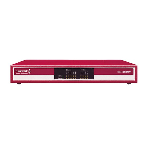
Funkwerk bintec R1200 User manual

Copyright ©December 13, 2006 Funkwerk Enterprise Communications GmbH
Version 3.0
User's Guide
bintec R1200 / R1200w(u) / R3000 / R3000w / R3400 / R3800(wu)
Wireless LAN

Purpose This document is part of the user’s guide to the installation and configuration of bintec gateways run-
ning software release 7.4.10 or later. For up-to-the-minute information and instructions concerning the
latest software release, you should always read our Release Notes, especially when carrying out a
software update to a later release level. The latest Release Notes can be found at www.funkwerk-
ec.com.
Liability While every effort has been made to ensure the accuracy of all information in this manual, Funkwerk
Enterprise Communications GmbH cannot assume liability to any party for any loss or damage caused
by errors or omissions or by statements of any kind in this document and is only liable within the scope
of its terms of sale and delivery.
The information in this manual is subject to change without notice. Additional information, changes and
Release Notes for bintec gateways can be found at www.funkwerk-ec.com.
As multiprotocol gateways, bintec gateways set up WAN connections in accordance with the system
configuration. To prevent unintentional charges accumulating, the operation of the product should be
carefully monitored. Funkwerk Enterprise Communications GmbH accepts no liability for loss of data,
unintentional connection costs and damages resulting from unsupervised operation of the product.
Trademarks bintec and the bintec logo are registered trademarks of Funkwerk Enterprise Communications GmbH.
Other product names and trademarks mentioned are usually the property of the respective companies
and manufacturers.
Copyright All rights are reserved. No part of this publication may be reproduced or transmitted in any form or by
any means – graphic, electronic, or mechanical – including photocopying, recording in any medium,
taping, or storage in information retrieval systems, without the prior written permission of Funkwerk En-
terprise Communications GmbH. Adaptation and especially translation of the document is inadmissible
without the prior consent of Funkwerk Enterprise Communications GmbH.
Guidelines and standards bintec gateways comply with the following guidelines and standards:
R&TTE Directive 1999/5/EG
CE marking for all EU countries and Switzerland
You will find detailed information in the Declarations of Conformity at www.funkwerk-ec.com.
How to reach Funkwerk
Enterprise Communications
GmbH
Funkwerk Enterprise Communications GmbH
Suedwestpark 94
D-90449 Nuremberg
Germany
Telephone: +49 180 300 9191 0
Fax: +49 180 300 9193 0
Internet: www.funkwerk-ec.com
Bintec France
6/8 Avenue de la Grande Lande
F-33174 Gradignan
France
Telephone: +33 5 57 35 63 00
Fax: +33 5 56 89 14 05
Internet: www.bintec.fr

Wireless LAN bintec User’s Guide 1
1Wireless LAN Menu . . . . . . . . . . . . . . . . . . . . . . . . . . . . . . . . . . . . . . 3
2Wireless Interfaces Submenu . . . . . . . . . . . . . . . . . . . . . . . . . . . . . 7
2.1 ACL Filter Submenu . . . . . . . . . . . . . . . . . . . . . . . . . . . . . . . . . . . . . . . . . 14
2.2 IP and Bridging Submenu . . . . . . . . . . . . . . . . . . . . . . . . . . . . . . . . . . . . 15
3WDS Link Configuration Submenu . . . . . . . . . . . . . . . . . . . . . . . . 19
4Advanced . . . . . . . . . . . . . . . . . . . . . . . . . . . . . . . . . . . . . . . . . . . . . 23
Index: Wireless LAN . . . . . . . . . . . . . . . . . . . . . . . . . . . . . . . . . . . . 27

2 bintec User’s Guide Wireless LAN

Wireless LAN bintec User’s Guide 3
Wireless LAN Menu 1
1 Wireless LAN Menu
The fields of the WIRELESS LAN menu are described below.
The WIRELESS LAN menu contains the general settings for the configuration of
the gateway as an ➤➤ access point (AP).
Wireless LAN (WLAN = Wireless Local Area Network) comprises the setup of a
network by means of radio technology.
Network functions WLAN provides the same required network functions as a cabled network, i.e.
access to servers, files, printers and mail system as well as the company Inter-
net access. No cabling is required, so that with a WLAN no edificial constraints
are to be considered (i.e. location of device is independent of position and num-
ber of connections).
Standard:
IEEE 802.11
802.11 WLANs offer all functions of a cabled network. WLAN transmits indoors
and outdoors at a maximum of 100 mW.
R3000w Setup Tool Funkwerk Enterprise Communications GmbH
[WLAN-8-0]: Configure WLAN Interface MyGateway
Operation Mode Off
Location Germany
Radio Band 2,4 GHz
Channel auto
Wireless Interfaces >
WDS Link Configuration >
Advanced >
SAVE CANCEL
Note
Please note that not all bintec gateways are equipped with radio technology.
Refer to the data sheet on www.funkwerk-ec.com to check whether your gate-
way supports it.

1
4 bintec User’s Guide Wireless LAN
Wireless LAN Menu
IEEE 802.11g is presently the primarily used standard for radio-based LANs
and offers a maximum data transfer rate of 54 Mbps. This method operates at
a frequency of 2,4 GHz (2400 MHz - 2485 MHz), which guarantees that build-
ings are penetrated with the required transmitting power that, however, does not
affect health.
802.11b is compatible with 802.11g, operating with 2,4 GHz (2400 MHz -
2485 MHz) too and offering a data transfer rate of 11 Mbps. 802.11g and
802.11b WLAN systems are free of charge and need not be registered.
802.11a is available in the 5 GHz range (5150 MHz - 5725 MHz). In Germany,
this frequency range need not be registered, either.
In Europe a transmitting power of 1000 mW (outdoor only) instead of 30 mW is
available with 802.11h as an extension of 802.11a, but has to be applied with
TPC (TX Power Control, methode to control the transmitting power of radio
equipment to reduce interferences) and DFS (Dynamic Frequency Selection).
TPC and DFS are applied to avoid interferences with satellite communication
and radar equipment.
The WIRELESS LAN menu consists of the following fields:
Field Description
Operation Mode Defines, whether the gateway operates as ac-
cess point (Access Point) or not (Off, default va-
lue).
Location The country setting of the AP.
Possible values are all countries preconfigured
on the wireless module of the gateway.
The range of the optional channels differs
according to the country setting selected.
Default value is Germany.

Wireless LAN bintec User’s Guide 5
Wireless LAN Menu 1
Table 1-1: WIRELESS LAN menu fields
The menu provides access to the following submenus:
■WIRELESS INTERFACE
Radio band Frequency range the access point is to operate
in.
Possible values:
■2,4 GHz (default value)
■5 GHz
Usage area Only for RADIO BAND = 5 GHz
Installation location of the access point.
Possible values:
■anywhere (default value): The access point
is to operate indoors and outdoors.
■indoor: The access point is to operate in-
doors.
■outdoor: The access point is to operate out-
doors.
Channel The channel used by the access point.
Possible values:
■auto (default value): the channel is detected
automatically;
option for RADIO BAND = 5 GHz.
■1 ... 13: only for RADIO BAND = 2,4 GHz
(1 ... 11 for LOCATION = United States
■149 ... 165 for RADIO BAND = 5 GHz and for
LOCATION = Austria or United States.
Field Description

1
6 bintec User’s Guide Wireless LAN
Wireless LAN Menu
■WDS LINK CONFIGURATION
only for RADIO BAND = 2,4 GHz
■ADVANCED

Wireless LAN bintec User’s Guide 7
Wireless Interfaces Submenu 2
2 Wireless Interfaces Submenu
The fields of the WIRELESS INTERACES menu are described below.
The WIRELESS LAN ➜WIRELESS INTERFACES submenu displays a list with already
configured wireless interfaces and contains essential settings such as network
name, status, security mode etc. The '*' in front of the NETWORK NAME
(➤➤ SSID) means that the network name is visible on ➤➤ active probing.
Each wireless interface (with prefix ➤➤ vss) has its own IP settings and can
use all standard interface specific features such as QoS, Stateful Inspection,
Accounting, Access Lists, NAT etc. This opens a wide range of applications for
the WLAN interface.
The bintec WLAN gateway not only offers bridging for wireless connections, but
is also fully integrated into the routing environment.
Securing your WLAN
Security As WLAN uses the air as transmission medium, the transferred data can theo-
retically be intercepted and read by anyone with the respective means. Thus,
safeguarding the radio link is to be paid special attention.
R3000w Setup Tool Funkwerk Enterprise Communications GmbH
[WLAN-8-0][WIRELESS]: Interface List MyGateway
Network Name Status Security ACL-Filter ifc Cl.#
-----------------------------------------------------------------
*Funkwerk-ec enable NONE disable vss8-0 16
ADD DELETE EXIT

2
8 bintec User’s Guide Wireless LAN
Wireless Interfaces Submenu
WEP 802.11 defines the security standard WEP (Wired Equivalent Privacy = data en-
cryption with 40/64 bit (SECURITY MODE = WEP 40/64) resp. 104/128 bit
(SECURITY MODE = WEP 104/128)). The commonly used WEP, however, turned
out to be vulnerable. For increased security you have to configure hardware-ba-
sed encryption (as e.g. 3DES or AES) additionally. Thus even sensitive data
can be transferred via the WLAN.
IEEE 802.11i The IEEE 802.11i standard for wireless systems comprises security specifica-
tions for radio networks especially concerning encryption. The relatively unse-
cure WEP (Wired Equivalent Privacy) is replaced by WPA (Wi-Fi Protected
Access). In addition, the Advanced Encryption Standard (AES) is defined for
data encryption.
WPA WPA (Wi-Fi Protected Access) offers increased protection by means of dynam-
ic keys, which are based on the Temporal Key Integrity Protocol (TKIP), and of-
fers PSK (Pre-Shared-Keys) or Extensible Authentication Protocol (EAP) via
802.1x (e.g. via RADIUS) for the authentication of users.
The authentication via EAP is normally used in vast Wireless LAN installations,
because it requires an authentication server (e.g. a RADIUS server). In smaller
networks, mostly for SoHo (Small Office, Home Office), PSK (Pre-Shared-
Keys) are normally used. All participants of the Wireless LAN must thus know
the PSK, as the session key is generated by means of it.
WPA2 WPA2 is the successor of WPA. It implements the full 802.11i-standard and
uses the encryption algorithm AES (Advanced Encryption Standard).
Security options To safeguard the data transferred via WLAN, you should make use of the re-
spective options of the WIRELESS LAN ➜WIRELESS INTERFACES menu (Appropri-
ate WLAN settings are to be done on the WLAN Clients):
■Change the default SSID, NETWORK NAME = Funkwerk-ec,of your access
point.
■Set WIRELESS INTERFACES ➜ NAME IS VISIBLE = no. Thus all WLAN clients are
refused who try to connect with the common NETWORK NAME (SSID) Any
and do not know the specified SSIDs.
■Use one of the provided encryption methods by selecting SECURITY MODE =
WEP 40/64, WEP 104/128, WPA PSK or WPA (802.1x) and entering the re-
Wireless LAN bintec User’s Guide 9
Wireless Interfaces Submenu 2
spective key for the access point into KEY 1 - 4 or ENTER PRESHARED KEY or
in RADIUS Server.
■The WEP key should regularly be changed by modifying the DEFAULT KEY.
Chose the longer WEP key with 104/128 bits.
■Highest security provides SECURITY MODE = WPA (802.1x) with WPA/WPA2
MIXED MODE = WPA2 only. These methods comprise hardware based encry-
tion and RADIUS authentication of the client. Additionally, even a combined
operation with IPSec is possible.
■Limit the access to the WLAN for allowed clients by entering the MAC
adresses of the WLAN cards of these clients into the MAC FILTER ➜
ACCEPT list. All other clients are rejected and listed under REJECT.(see
“ACL Filter Submenu” on page 14).
The generation of new wireless interfaces is carried out in WIRELESS LAN ➜
WIRELESS INTERFACES ➜ADD:
The adjustment of already configured wireless interfaces is carried out in
WIRELESS LAN ➜WIRELESS INTERFACES ➜EDIT:
R3000w Setup Tool Funkwerk Enterprise Communications GmbH
[WLAN-8-0][WIRELESS][ADD]: Wireless Interface MyGateway
AdminStatus enable
Network Name
Name is visible yes
Max. Clients 16
Security Mode NONE
SAVE CANCEL

2
10 bintec User’s Guide Wireless LAN
Wireless Interfaces Submenu
The WIRELESS LAN ➜ WIRELESS INTERFACES menu consists of the following
fields:
R3000w Setup Tool Funkwerk Enterprise Communications GmbH
[WLAN-8-0][WIRELESS][EDIT]: Wireless Interface MyGateway
AdminStatus enable
Network Name Funkwerk-ec
Name is visible yes
Max. Clients 16
Security Mode NONE
ACL Filter >
IP and Bridging >
SAVE CANCEL
Field Description
AdminStatus Defines the administrative status of the wireless
interface.
Possible values:
■enable (default value): enable the interface
■disable: disable the interface
Network Name Name of the wireless interface (SSID).
Enter an ASCII string of max. 32 characters.
Name is visible Enable broadcasting of the network name
(SSID) of the wireless interface.
Possible values:
■yes (default value): network name is visible
for clients within reach.
■no: network name is hidden for the clients.

Wireless LAN bintec User’s Guide 11
Wireless Interfaces Submenu 2
Max. Clients Maximum number of WLAN client connections
allowed for this interface. All in all 64 connec-
tions can be distributed to all wireless inter-
faces.
Security Mode Here you select the security mode (encryption
and authentication) of the wireless interface.
Possible values:
■NONE (default value): no encryption or au-
thentication
■WEP 40/64: WEP 40Bit
■WEP 104/128: WEP 104Bit
■WPA PSK: WPA with Preshared Key au-
thentication
■WPA (802.1x): WPA with EAP (RADIUS-
authentication)
If SECURITY MODE is set to WPA (802.1x) the fol-
lowing note is displayed: A Radius Server
configuration in RADIUS setup is required.
Default Key Only for SECURITY MODE = WEP 40/64, WEP
104/128
Here you select one of the configured keys in
KEY <1 - 4> to be the one used as default key.
Default value is Key 1.
Field Description

2
12 bintec User’s Guide Wireless LAN
Wireless Interfaces Submenu
Key <1 - 4> Only for SECURITY MODE = WEP 40/64, WEP
104/128
Here you enter the WEP key. WEP keys can be
entered in two different ways:
■Direct Digit Input in hexadecimal format
Enter the key with the exact count of hexa-
decimal digits for the selected WEP mode.
10 digits for WEP40 or 26 digits for
WEP104.
E.g.
WEP40: A0B23574C5,
WEP104:
81DC9BDB52D04DC20036DBD831
■Direct ASCII based input
Enter a phrase with the exact count of digits
for the selected WEP mode. Confirming
with the input key transforms the ASCII
based input into a hexadecimal phrase. For
WEP40 the phrase must have 5 characters,
for WEP104 13 characters.
E.g.
hallo for WEP40
funkwerk-wep1 for WEP104.
Field Description

Wireless LAN bintec User’s Guide 13
Wireless Interfaces Submenu 2
Table 2-1: WIRELESS INTERFACES menu fields
Enter Preshared Key Only for SECURITY MODE = WPA PSK
Here you enter the WPA passphrase.
Enter an ASCII String of 8 - 63 characters.
WPA/WPA2 mixed mode Only for SECURITY MODE = WPA PSK and
WPA (802.1x)
Here you select whether to apply WPA (with
TKIP encryption) or WPA2 (with AES encryp-
tion) or both. Possible values:
■WPA + WPA2 (default value for the initial
provided interface)
■WPA only (default value for all other inter-
faces)
■WPA2 only
WPA2 preauthentication Only for SECURITY MODE = WPA 802.1x with
WPA/WPA2 MIXED MODE = WPA + WPA2 and
WPA2 only
With this option registered clients can be pre
authenticate at other access points in the same
radio cell. Thus these clients can change faster
to the other access point ("roaming"), as the
RADIUS authentication can be omitted during
registration. The preauthentication is only pos-
sible with the client being registered at the
access point with WPA2.
Possible values:
■enabled (default value): The Access Point
allows preauthentication of clients at other
access points.
■disabled: Preauthentication requests of cli-
ents are ignored.
Field Description

2
14 bintec User’s Guide Wireless LAN
Wireless Interfaces Submenu
2.1 ACL Filter Submenu
The fields of the ACL FILTER submenu are described below.
In the WIRELESS LAN ➜WIRELESS INTERFACES ➜MAC FILTER submenu, hard-
ware specific acces control is configured. Thus it is possible to allow only spe-
cific clients to access the access point. This filter is checked before any other
security mechanism is activated. The entered addresses are MAC based.
MAC Address Lists The ACCEPT list displays all MAC addresses to be accepted for the wireless
interface.
The REJECT list displays all rejected addresses.
Default behaviour: If ADMINSTATUS = disabled, all clients are accepted. As soon
as ADMINSTATUS = enabled is set and no MAC address is listed in the ACCEPT
list, all clients are blocked. Only those clients whos MAC addresses are then en-
tered manually into the ACCEPT list or are moved from the REJECT to the
ACCEPT list are accepted.
Additional buttons The REFRESH button reloads the REJECT list, so that at any time the current
status of rejects can be listed.
R3000w Setup Tool Funkwerk Enterprise Communications GmbH
[WLAN-8-0][WIRELESS][EDIT][ACCESS LIST]: Interface MyGateway
<Funkwerk-ec>
AdminStatus disable
Accept Address ADD
ACCEPT REJECT
---------------------- ----------------------
Press 'a' to move selected Reject Address to Accept List.
SAVE REMOVE EXIT REFRESH

Wireless LAN bintec User’s Guide 15
Wireless Interfaces Submenu 2
With the REMOVE button selected addresses can be deleted from the ACCEPT
list. Removing an address from the ACCEPT list immediately disconnects an es-
tablished link.
The menu consists of the following fields:
Table 2-2: ACL FILTER menu fields
2.2 IP and Bridging Submenu
The fields of the IP AND BRIDGING submenu are described below.
Field Description
AdminStatus Enable or disable the filter for this wireless
interface.
Possible values: enable, disable (default value)
Accept Address Enter a MAC address to be accepted.
Possible values: 12 digit MAC addresses; the
addresses are entered without any ":".
Press ADD to add the entered MAC address to
the ACCEPT list.
If you highlight an entry from the REJECT list
and press a(must be lowercase) on your key-
board, the respective entry is moved to the
ACCEPT list. Thus you do not have to manually
enter acceptable addresses.

2
16 bintec User’s Guide Wireless LAN
Wireless Interfaces Submenu
In the WIRELESS LAN ➜WIRELESS INTERFACES ➜EDIT ➜IP AND BRIDGING sub-
menu you enter the interface specific IP configuration and activate the bridging
mode if applicable.
The menu consists of the following fields:
R3000w Setup Tool Funkwerk Enterprise Communications GmbH
[WLAN-8-0][WIRELESS][EDIT][IP CONFIGURATION]: WLAN VSS MyGateway
Interface <Funkwerk-ec>
Local Communication disabled
Local IP Address
Local Netmask
Second Local IP Address
Second Local Netmask
Bridging enable no
Proxy ARP no
SAVE CANCEL
Field Description
Local Communication Allows the communication between the clients,
authenticated at this SSID, to e.g. access com-
mon shares.
Possible values:
■enabled
■disabled (default value).
Local IP Address Here you assign an IP address to the wireless
interface.
Local Netmask Netmask for LOCAL IP NUMBER.

Wireless LAN bintec User’s Guide 17
Wireless Interfaces Submenu 2
Table 2-3: IP AND BRIDGING menu fields
Second Local IP Address Here you assign a second IP address to the
wireless interface.
Second Local Netmask Netmask for SECOND LOCAL IP NUMBER.
Bridging enable Enables activating the Bridging mode.
Possible values:
■no (default value): Bridging is not enabled
on the wireless interface.
■yes: Bridging is enabled on the wireless in-
terface.
Proxy ARP Enables the gateway to answer ARP requests
from its own LAN acting for WLAN Clients.
Possible values:
■no (default value)
■yes.
Field Description

2
18 bintec User’s Guide Wireless LAN
Wireless Interfaces Submenu
Other manuals for bintec R1200
3
This manual suits for next models
5
Table of contents
Other Funkwerk Network Router manuals

Funkwerk
Funkwerk bintec R230a User manual

Funkwerk
Funkwerk elmeg t444 User manual

Funkwerk
Funkwerk R3400 User manual

Funkwerk
Funkwerk R3000w User manual

Funkwerk
Funkwerk bintec R4100 User manual

Funkwerk
Funkwerk bintec R4100 User manual

Funkwerk
Funkwerk bintec R230a User manual

Funkwerk
Funkwerk bintec R230a Instruction manual

Funkwerk
Funkwerk bintec R1200 User manual

Funkwerk
Funkwerk bintec R230a User manual