FunRunner 100 Series User manual

Utility Vehicle
Model Series
100 & 101
PRINTED IN U.S.A.
OPERATOR’S MANUAL
FORM NO.
770-10434A.fm
(5/01)
IMPORTANT: READ SAFETY RULES AND INSTRUCTIONS CAREFULLY
FunRunner P.O. BOX 360920 CLEVELAND, OHIO 44136

2
TABLE OF CONTENTS
Content Page
Important Safe Operation Practices...................................................................3
Know Your Utility Vehicle...................................................................................5
Operating Your Utility Vehicle............................................................................8
Maintaining Your Utility Vehicle..........................................................................9
Accessories.......................................................................................................10
Specifications ....................................................................................................11
Troubleshooting.................................................................................................12
Parts List............................................................................................................14
FINDING MODEL NUMBER
This Operator’s Manual is an important part of your new utility vehicle. It will help you assemble, prepare
and maintain the unit for best performance. Please read and understand what it says.
Before you use your new utility vehicle, please locate the model plate on the vehicle
under the left side of dash panel and copy the information from it in the space provided
below. The information on the model plate is very important if you need help from our
Customer Support Department or an authorized center.
• A sample model plate is explained below. For future reference, please copy the model number and
the serial number of the equipment in the space below.
CALLING CUSTOMER SUPPORT
If you have any questions regarding the controls, operation or maintenance of this unit, please call the
Customer Support Department.
Call Toll Free at 1-866-FUN-RUNR or 1- (866)-386-7867 to reach a customer support
representative. Please have your unit’s model number and serial number ready when you
call. See previous section to locate this information. You may be asked to enter the serial
number in order to process your call.
Copy the model number here:
Copy the serial number here:
(Model Number) (Serial Number)
CLEVELAND, OHIO 44136
FunRunner
P.O. BOX 360920
For more details about your unit, visit our website at www.FunRunner.com

3
SECTION 1: IMPORTANT SAFE OPERATION PRACTICES
WARNING: This symbol points out important safety instructions which, if not followed, could
endanger the personal safety and/or property of yourself and others. Read and follow all instructions in
this manual before attempting to operate or service this vehicle. When you see this symbol - heed its
warning.
WARNING: This product contains or emits chemicals known to the State of California
to cause cancer, birth defects or other reproductive harm.
DANGER:This vehicle is designed to be operated according to the rules for safe operation in this
manual. As with any type of vehicle, carelessness or error on the part of the operator can result in
serious injury. Failure to observe the following safety instructions could result in serious injury or death.
General Operation
1. Read, understand, and follow all instructions on the
vehicle and in the manual before attempting to
operate or service. Keep this manual in a safe
place for future and regular reference and for
ordering replacement parts.
2. Be familiar with all instruments and controls and
their proper operation before starting vehicle.
3. Never allow children under 14 years old to operate
this vehicle. Children 14 years old and over should
read and understand the operation instructions and
safety rules in this manual and should be trained
and supervised by a parent.
4. Never allow adults to operate this vehicle without
proper instruction.
5. Watch for traffic when operating near or crossing
roadways. This vehicle is not intended for use on
any public roadway.
6. Do not operate this vehicle while under the
influence of alcohol or drugs.
7. Never carry passengers. This vehicle is designed
to carry one person only, the operator.
8. Always remain seated and keep both hands on the
steering wheel when driving the vehicle.
9. Always keep your hands and feet in the vehicle
when driving the vehicle.
10. Inspect area around vehicle before moving, espe-
cially in reverse. Back up slowly. Always look down
and behind before and while backing to avoid a
back-over accident.
11. Slow down before turning and while operating on
wet and slippery surfaces. Operate the vehicle on
smooth terrain. Avoid erratic operation and
excessive speed.
12. Always use vehicle lights while operating in low
light situations.
13. Never leave vehicle unattended with the key in the
“On” forward or reverse position. Always turn key to
the “Off” position, set the parking brake and remove
key before dismounting.
14. Use extra care when loading or unloading the
vehicle into a trailer or truck. This unit should not be
driven up or down loading ramp(s), because the
unit could tip over, causing serious personal injury.
The unit must be pushed manually on loading
ramp(s) to load or unload properly.
15. Checkoverheadclearancescarefullybeforedriving
under low hanging tree branches, wires, door
openings etc., where the operator may be struck or
pulled from the unit, which could result in serious
injury.
16. Do not exceed the load capacity of 300 lbs., which
includes driver, accessories and cargo.
17. Improper use of the vehicle or failure to properly
maintain it could result in decreased vehicle
performance or personal injury.
18. Use only accessories and attachments approved
for this vehicle by the manufacturer. Read,
understand, follow all instructions provided with the
approved accessory or attachment.
19. If situations occur which are not covered in this
manual, use care and good judgement. Contact
your local service center or call toll free 1-866-386-
7867 for assistance and the name of your nearest
service center.
Slope Operation
Slopes are a major factor related to loss of control and
tipover accidents, which can result in severe injury or
death. If a slope is steeper than a 20% grade (11°), do
not operate this unit on that area. Exercise extreme
caution while operating on slopes.
DO:
1. Travel straight up and down slopes, not across.
Exercise extreme caution when changing direction
on slopes.
2. Watch for holes, ruts, bumps, rocks, or other
hidden objects. Uneven terrain could overturn the
vehicle.
3. Travel slowly while on a slope. Tires may lose
traction on slopes even though the brakes are
functioning properly. Always keep the forward

4
speed limited when going down slopes to take
advantage of the motor braking action.
4. Keep all movement on the slopes slow and gradual.
Avoid starting or stopping on a slope.
5. Use extra care while carrying cargo. It may affect
the stability of the vehicle.
Do Not:
1. Do not turn on slopes unless necessary; then turn
slowly and gradually downhill, if possible.
2. Do not travel near drop-offs, ditches or embank-
ments. The vehicle could suddenly turn over if a
wheel is over the edge of a cliff, ditch, or if an edge
caves in.
3. Do not try to stabilize the vehicle by putting your
foot on the ground.
4. Do not carry cargo on steep slopes.
5. Travel with caution on wet grass. Reduced traction
could cause sliding.
Children
1. Tragic accidents can occur if the operator is not
alert to the presence of children. Children are often
attracted to the vehicle. They do not understand the
dangers. Never assume that children will remain
where you last saw them.
a. Keep children out of the immediate area of
the vehicle and in watchful care of a
responsible adult other than the operator.
b. Be alert and turn the vehicle off if a child
enters the area.
c. Before and while backing, look behind and
down for small children.
d. Never carry children, they may fall off and be
seriously injured or interfere with safe vehicle
operation.
e. Use extreme care while approaching blind
corners, doorways, shrubs, trees or other
objects that may block your vision of a child
who may run into the path of the vehicle.
f. Remove key when vehicle is unattended to
prevent unauthorized operation.
2. Never allow children under 14 years old to operate
this vehicle. Children 14 years old and over should
read and understand the operation instructions and
safety rules in this manual and should be trained
and supervised by a parent.
Service
1. Only trained mechanics should repair or service the
vehicle. For small repairs or service, follow the
procedures exactly as stated in this manual, and
follow all DANGER, WARNING, and CAUTION
procedures listed in this manual and on the vehicle.
2. Before servicing,repairing, orinspecting turn the
ignition key switch to “OFF”and remove the key.
Turn the battery disconnect switch, located under
the seat, to “OFF”or “0”position. See parts list for
location of battery switch.
3. Always wear safety glasses or safety goggles while
servicing the vehicle.
4. Always use insulated tools when working around
batteries or electrical connections.
5. Check brake operation frequently as it is subjected
to wear during normal operation. See authorized
service center as required.
6. Keep all nuts, bolts, and screws tight to be sure the
equipment is in safe working condition.
7. Any modification or change to the vehicle that
increases maximum vehicle speed beyond factory
specifications could result in serious injury or death.
8. Maintain or replace safety and instruction labels, as
necessary.
WARNING: Your Responsibility: Restrict
the use of this vehicle to persons who read,
understand and follow the warnings and
instructions in this manual and on the unit.

5
SECTION 2: KNOW YOUR UTILITY VEHICLE
NOTE: Reference to right or left hand side of the utility vehicle is observed from the operating position.
Figure 1
Read this operator’s manual, safety labels, and
operating instructions on the vehicle before operating.
Compare the illustrations in this manual with your unit
to familiarize yourself with the location of various
controls and adjustments. Reference to the right or left
hand side of unit is observed from the operating
position. Save this manual for future reference.
See Figure 1.
NOTE: Before operating your vehicle, follow the
starting instructions in the Operating Section and
check tire pressure per the recommendations in the
Maintenance Section.
Ignition Switch
The ignition switch is located on the lower right dash
panel and it is used to power up the vehicle. To operate
the vehicle in forward, insert key in the ignition switch
and turned from the OFF position clockwise to: H (High
Speed) or L (Low Speed). To operate the vehicle in
reverse, the key needs to be turned counter-clockwise
to R (Reverse). See Figure 2.
12V Power Outlet
The 12V power outlet is located on the lower left dash
panel. It is used for the convenience of plugging in
accessories that require a power source with a
maximum load of 5 amps at 12 volts. See Figure 2.
Figure 2
Ignition Switch
12V Power
Outlet
12V Power
Outlet
Ignition
Switch
ROFFHL

6
Brake and Parking Brake Pedal
The brake and parking brake pedal is located on the left
side of the floor beneath the dash panel. The pedal is
divided into two sections. By depressing the lower and
larger section, the pedal will activate the rear wheel
brakes to slow or stop the vehicle and it will also
activate the brake lights. The top left or small
rectangular section of the pedal is the parking brake
and it should be engaged when the unit is not in use.
See Figure 3.
•To engage the parking brake, depress the top left
(rectangular) of the pedal down to lock in position.
•To release parking brake, press down on the brake
portion (larger section) all the way to the floor and
release.
NOTE: The motor braking system will slow the vehicle
when the accelerator pedal is released, but the brake
pedal should be used to stop vehicle completely.
Accelerator Pedal
The accelerator pedal is located on the right side of the
floor beneath the dash panel. Depressing the
accelerator pedal will move the vehicle in the direction
selected on the ignition switch (Forward or Reverse).
As the pedal is depressed, speed will increase to the
maximum selected range. When the pedal is released
the vehicle will slow gradually to a stop. See Figure 3.
NOTE: This vehicle is equipped with a reverse beeper,
which will sound to warn the operator and others that
the vehicle is being operated in reverse.
Figure 3
InstrumentCluster
The instrument cluster is located near the top of the
dash panel. There are three indicator gauges: battery
gauge, speedometer with odometer, and temperature
gauge. The battery gauge will display the amount of
charge left in the battery. The temperature gauge will
display the temperature of the electric drive system. If it
shows to be high, park and turn off vehicle and let cool.
The speedometer will indicate the speed the vehicle is
traveling. Below these gauges are various indicators
and that will illuminate when the corresponding signal
or function is activated, i.e. Fault Light, Temp, Battery,
R (Reverse), ON, H (High Speed), L (Low Speed),
Charging, Parking Brake, and Lights. See Figure 4.
Figure 4
Indicator Lights
NOTE: The fault light flashes when there is a system
error. Refer to the troubleshooting guide when the fault
light flashes or when the vehicle is not operating
properly.
Cup Holder
The cup holder is located on the right side of the dash
panel. It is designed for the use of non-alcoholic
beverages.
WARNING: Never operate this vehicle
while under the influence of alcohol or
drugs. Doing so can result in serious
personal injury or death.
Hazard Light Switch
The hazard light switch is located on the dash panel
beneath the steering wheel. Push bottom/top of switch
to activate or turn off hazard lights. See Figure 5.
Horn Switch
The horn switch is located on the dash panel beneath
the steering wheel. Push bottom/top of switch to
activate or turn off horn. See Figure 5.
Headlights/Taillights Switch
The headlights/taillights switch is located on the dash
panel beneath the steering wheel. Push bottom/top of
switch to activate or turn off lights. See Figure 5.
Accelerator
Pedal
Parking
Brake
Brake
Battery
Gauge
Speedometer
Temperature
Gauge
Indicators
Direction
Arrow
Lights
Fault
Light
Temperature
Battery
Reverse
Vehicle
“ON”
High
Speed
Low
Speed
Charging
Parking
Brake
Lights
RON HL
P
!

7
Figure 5
Turn Signal Lever
The turn signal lever is located on the left side of dash
panel behind the steering wheel. By moving the lever
back and forth, the corresponding signal will be
activated. The signal must be manually returned to the
neutral position. See Figure 6.
Figure 6
Locking Trunk (If Equipped)
Figure 7
If equipped, the locking trunk will be located in the rear
of the utility vehicle. The trunk can be opened and
locked with the trunk key. The weight limit for cargo in
the trunk basket is 50lbs. See Figure 7.
WARNING: Do not exceed the load
capacity of 300 lbs., which includes
driver, accessories, and cargo.
Adjustable Seat Lever
The adjustable seat lever is located beneath the seat
on the right front side and it is used to move the seat
forward and backward. See Figure 8.
•Slide the lever to the left and push the seat forward
or back to the desired position.
•Release the lever so that it locks the seat in place.
WARNING: Make sure seat is in locked
position prior to operation and do not try
to adjust the seat position while operating
the vehicle.
Charging Port
The charging port is located below the seat on the body
panel. Flip up the cap of the charging port to gain
access to charger plug. Use a minimum 16 AWG, 3-
wire outdoor extension cord and no more than 50 ft in
length to charge the batteries ofyour vehicle. See
Figure 8.
Figure 8
Battery Disconnect Switch
The battery disconnect switch is located under the seat
and it is used to disconnect the batteries from the rest of
the electrical system. Slide the seat forward to gain
access to the switch. The switch must be in the ON
position to operate the vehicle or charge the batteries.
See Figure 9.
Figure 9
Headlights/Taillights HornHazards
Turn Signal
Lever
Trunk Lid
Adjustable
Seat Lever
Charging
Port
Seat
Seat Battery Disconnect
Switch

8
SECTION 3: OPERATING YOUR UTILITY VEHICLE
Starting Utility Vehicle
• Inspect area around vehicle for any items which
may be in your path.
• Make sure battery disconnect switch under the seat
is in the ON position.
• Adjust seat to desired position.
• Insert the key into the ignition switch.
• Make sure wheels are turned to desired position.
• To drive forward, turn key from OFF position
clockwise to one of the forward speeds: H (High) or
L (Low).
• To drive in reverse, turn key counter-clockwise to R
(Reverse).
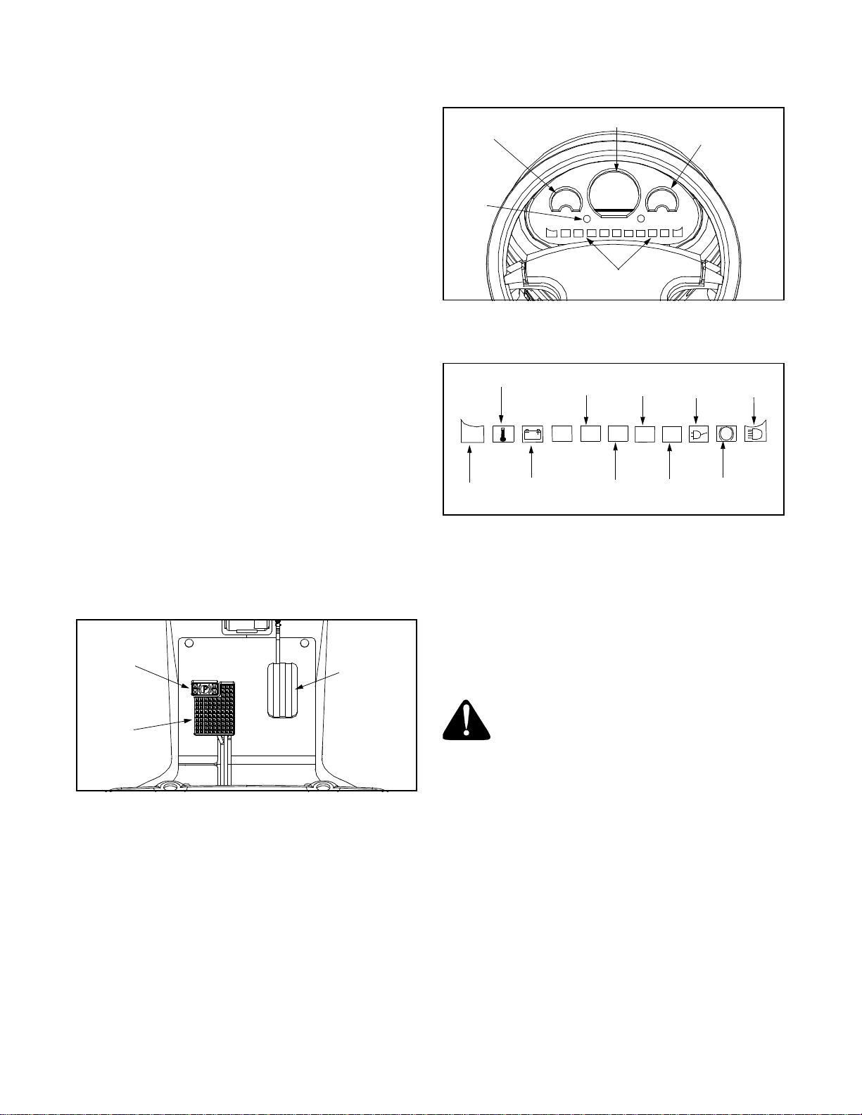
• Check instrument cluster for vehicle operating
conditions, i.e. battery or temperature.
a. If charging is needed proceed to Charging
Utility Vehicle in this section.
b. If temperature gauge shows to be high, park,
turn off vehicle and let cool.
• Release parking brake by depressing brake pedal
all the way to the floor and release.
• By turning key from the OFF position, an indicator
light will illuminate “ON”. After a couple of seconds
an indicator light will illuminate showing the speed
or direction, (H) High, (L) Low, (R) Reverse.
• After the speed or direction light is illuminated,
slowly depress accelerator pedal and the vehicle
will start to move until the maximum speed selected
is reached.
IMPORTANT:
If the accelerator is depressed before
the indicator light is illuminated showing the speed
or direction, the vehicle will not move, four “Beeps”
will sound, and the fault light on dash will flash four
times. The operator must remove their foot from the
accelerator, so the “Beeping” will stop and the
vehicle can be operated.
NOTE: If vehicle will not move and charging is not
needed, turn ignition key to OFF and then repeat
starting procedure.
• When driving in forward or reverse, the vehicle can
be switched to the opposite direction, by turning the
ignition switch QUICKLY to the other direction
WITHOUT STOPPING in the OFF position or stop-
ping the vehicle. This WILL NOT harm the vehicle.
Stopping in the OFF position when switching from
one direction to another while driving may cause a
“fault light” or system error to occur.
Stopping Utility Vehicle
• To stop utility vehicle, release accelerator pedal
and depress brake pedal until vehicle comes to a
complete stop.
• Just releasing accelerator pedal will also slow and
gradually stop the vehicle.
• After stopping the vehicle, firmly depress parking
brake pedal, top left of brake pedal, until it locks.
• Turn the ignition key to the OFF position and
remove the key when not in use.
IMPORTANT:
When stopped on a hill, use the brake
pedal to hold your position. Do not use the accelerator
pedal, this may cause damage to the electric drive
system.
Charging Utility Vehicle
The electric motor receives power from four batteries
stored under the seat. These batteries are sealed and
maintenance-free, so acid levels cannot be checked
and water cannot be added. When the accelerator
pedal is released the motor braking feature acts as a
power regenerator to the batteries.
Recharging the batteries is required when the battery
gauge on the instrument cluster indicates a low charge
when the vehicle is at rest or not under a heavy load.
The vehicle may also need charging if it has not been in
use for several days.
NOTE: When operating the vehicle under a heavy load
or an incline, the battery gauge may display a
temporary lower charge. This does not indicate
charging is needed.
WARNING: The electrical outlet for
charging your vehicle must be grounded
(GFCI protection) and accept a 3-prong
plug. The extension cord used for
charging must be a 3-wire grounding type
cord with a 3-prong plug. It must be a
minimum 16 AWG and be no longer than
50 feet. The use of an improper extension
cord could result in a fire or an electrical
shock. Always disconnect the extension
cord from the grounded ac outlet and
vehicle before driving vehicle.
• To recharge vehicle, plug a 3-prong 120V,ac
extension cord that is 16 gauge minimum and 50ft
maximum length (110-120V 60Hz) into a properly
grounded three-prong 120V, ac outlet (GFCI
protection).
• Insert the extension cord into the charging port on
the vehicle. Refer to Figure 8.
• It can take up to 7 to 8 hours to fully recharge the
batteries. Refer to the battery gauge on the
instrument cluster to determine level ofcharge.
• Before driving, disconnect the extension cord from
the grounded three-prong outlet first and then from
the charging porton the vehicle.

9
NOTE: The vehicle cannot be driven when the
extension cord is connected to the charging port.
•A fully charged vehicle can be operated up to 30
miles before a recharge is necessary, but it is not
necessary to let the batteries run down completely
in order to recharge again.
NOTE: The vehicle batteries cannot be overcharged or
overheated due to prolong charging. It is recommended
the vehicle be left in a charge mode to maintain a full
charge and extend battery life.
SECTION 4: MAINTAINING YOUR UTILITY VEHICLE
Electric Motor
The electric motor requires no maintenance. Any
service issues related to the motor should be directed
to an authorized service center.
Replacing Headlights/Taillights
Headlights
•Locate the back of each headlight from under the
dash panel.
•To remove the front hazard light, twist the rubber
connector and pull out of assembly.
•Replace light bulb.
•To remove the front headlight, twist the plastic con-
nector and pull out of assembly.
•Separate the plastic tabs and disconnect the light.
•Connect the new light to plastic connector and
replace.
Taillights
•Remove rear hazards the same as front hazards.
•To remove rear taillight, twist taillight connector and
pull out of assembly.
•Push down on light bulb and twist to remove bulb.
•Replace bulb and reconnect to assembly.
Batteries
The four batteries are located under the rear body
panel in front of the electric motor. They are all sealed
and maintenance free, so acid levels cannot be
checked and water cannot be added. Any service
issues related to batteries should be directed to an
authorized service center.
WARNING: Do not attempt to remove
batteries. This should be only be done by
an authorized service center only.
Tire Pressure
The recommended operating tire pressure is approxi-
mately 15 psi +/-2 psi for both the front and rear tires.
Overinflating above recommended tire pressure can
reduce the life of the tire. Check tire pressure before
driving the vehicle.
Wheel Replacement
•Stop the vehicle on a level surface. Firmly depress
parking brake pedal, located on top left of brake
pedal, until it locks.
•Turn the ignition key to the OFF position and
remove the key.
•If unit is equipped with hubcaps, pry hubcap off the
wheel needing repair.
•Loosen but do not remove the four lug nuts from the
axle studs.
•Jack up the vehicle to remove the wheel and
always block other wheels to prevent vehicle from
rolling. See Figure 10.
Figure 10
Jack Point
Jack Point

10
NOTE: Do not jack up vehicle on body parts, but use
strong sturdy points; such as the front arm assembly or
rear trailing arm frame assembly.
•Remove the lug nuts and old wheel. Place new
wheel on the axle studs and secure with lug nuts.
•Carefully lower vehicle on level surface and tighten
lug nuts to torque specifications.
•Tighten one lug nut at a time rotating clockwise to
50 - 55 ft-lbs clockwise and then repeat sequence
and torque to 100-105 ft-lbs.
•If equipped, snap hubcaps on wheel.
Cleaning
The body panels are scratch and impact resistant
automotive quality ABS plastic. The use of standard car
wash soap and non-abrasive car wax is acceptable for
cleaning the body panels. Avoid any abrasive cleaner
or rubbing compounds for these will damage the body
panels.
WARNING: Damage may occur if direct
hose spray comes in contact with the
electric motor located under the trunk
and/or any other electrical components,
i.e. at instrument cluster or under dash.
Towing
•Towing of this vehicle is not recommended;
however, if towing is a must, the key should be in
the off position and the key removed from the
ignition.
WARNING: Do not tow the vehicle on
public streets or highways and do not
allow anyone in the vehicle when its being
towed.
Storage
•Turn the ignition key to the OFF position and
remove the key when not in use.
•Fully charge batteries according to Charging Utility
Vehicle in the Operation Section.
•Store vehicle in a cool, dry place. This will prevent
self-discharge of the batteries.
NOTE: It is recommended the vehicle be left plugged in
to maintain a full charge and extend battery life when
not in use.
•When returning vehicle to service, check if battery
disconnect switch is turned ON, batteries fully
charged, and check tire pressure.
Key Replacement
•If an additional or replacement ignition or trunk keys
are needed; call Toll Free at 1-866-FUN-RUNR or
1- (866)-386-7867 to reach a customer support
representative or see an authorized service center.
SECTION 5: ACCESSORIES
NOTE: Some of these accessories may come
already equipped on your vehicle. If they are not
equipped, they may be ordered through your local
retailer or an authorized service center.
Description Model Number
4 cu-ft Utility Bed w/Tailgate 39A-001-000
Canopy 39A-002-000
Windshield 39A-003-000
Golf Package 39A-004-000
Hub Caps (See Parts List) 39A-005-000
Arm Rests (See Parts List) 39A-006-000

11
SECTION 6: SPECIFICATIONS
Body Dimensions/Weight
Overall Length 79”(201 cm)
Overall Width 31.5”(80 cm)
Wheel Base 48”(122 cm)
Overall Height: At Seat 26”(66 cm)
Ground Clearance 4”(10 cm)
Step Height 8.5”(21.25 cm)
Vehicle Weight 600 lbs. (272.7 kg)
(Includes Batteries)
Battery Weight 210 lbs. (95.3kg)
Load Capacity 300 lbs. (136.3 kg)
(Includes Driver, Accessories &
Cargo)
Power Source
Motor 48V Brush DC
Batteries 12V Maintenance Free (4)
Battery Rating 132 min. 73 amp-hr @
20 hr Discharge Rate
Controller 150 amp peak, 60 amp
cont; 48V Sealed
Charger (On-Board) 110V - 6 amp
Charge Time 7 - 8 hrs.
Steering
Type Sector and Pinion
Clearance Circle 16.1 ft. (4.9m)
Speed/Performance
Max Forward High Speed 12 m.p.h. (20 km/h)
Max Forward Low Speed 8 m.p.h. (13km/h)
Max Reverse Speed 5 m.p.h. (8km/h)
Acceleration 0-12 m.p.h. 6 sec.
Range Up to 30 mi (50km)
Brakes
Type Dual Rear Wheel
Mechanical Drum Brakes
(Self Adjusting)
Parking Brake
Motor Braking
Suspension
Front Independent
Rear Trailing Arm
Tires
Front 16.2”x 4.7”
Rear 16.6”x 6.4”
Transmission
Gear Ratio 14:1 ratio

12
SECTION 7: TROUBLESHOOTING
If you are NOT experiencing one of the below problems and an electrical system error is occurring with the “fault
light”flashing or an “audible signal”being heard, perform these corrective actions.
1. Turn ignition key to OFF position or “power down”vehicle and repeat starting procedures.
2. Turn OFF or “power down”vehicle, turn battery disconnect switch to OFF andthen ON. Repeat starting
procedures.
3. Contact an authorized service center if problem persists.
* Indicates number of flashes
Problem Fault
Light* Audible
Signal Possible Cause(s) Corrective Action
Vehicle is operating at half
speed and battery light
flashing.
(2) 1. Battery voltage approaching
lower limit.
2. Speed sensor disconnected.
3. Speed sensor malfunctioning.
1. Chargebatteryand contact an
authorized service center if
problem persists.
Vehicle will notmove and the
charge light is illuminated. (7)
(1) 1. Startup with charger plugged in.
2. Charger plugged in after
startup.
1. Unplug charger to operate vehicle.
“Charging”light is flashing. 1. Charger pluggedin after
batteries are fully charged.
2. Poor charger connection.
3. One or more batteries failed.
1. Unplug charger, turn on vehicle,
and check battery gaugefor full
charge.
2. Checkextensioncordconnections.
3. Contact an authorized service
center if problem persists.
“Low”light is flashing. 1. Braking too aggressively at
high speeds.
2. Exceeding current limit.
1. Turn OFF vehicle, turn battery
disconnect switch to OFFand then
ON. Repeat starting procedures.
2. Do not operate on slopesover 11°.
Temperature gauge indicates
high on instrument panel and
vehicle power is limited.
Charging light is flashing.
(4)
(5)
1. System temperature high.
2. System sink temperature
excessively high.
3. Temperature is high enough to
cause shutdown.
1. Turn OFF vehicle and let cool and
contactan authorized service
center if problempersists.
Loss of power on an incline. (6) 1. Climbing a hill that is too steep.
2. Climbing an incline that is too
long.
3. Abusing the electrical drive
system.
1. Operate vehicle on flat ground or
turn off vehicle andlet cool.
Vehicle will notmove and
brake lights are on. 1. When brake switch is activated
vehicle will not move. 1. Release brake pedal and contact
an authorized service center if
problem persists.
Loss of power on a decline. (7) 1. Motor braking causing too
much power to be channeled
back intothe batteries (over
charge danger).
1. Operate vehicle on flat ground or
turn off vehicleand let cool.

13
Notes

14
Model Series 100 & 101
5
10
11
12
14
15
16 17
18
19
20
21
22 8
23 24
25
26
26
28
30 31
32 33
35
36
37
27 29
8
13
6
7
9
1
2
34
34
38 39
40
42
41
3

15
Model Series 100 & 101
REF.
NO. PART
NO. DESCRIPTION
1. 731-2343 Steering Wheel Cap
2. 710-0643 Hex Cap Screw 5/16-18 x 1.0
3. 736-0159 Bell Washer
4. 731-2342 Steering Wheel
5. 611-0139 Shaft Assembly
6. 715-0151 Spiral Pin
7. 723-0487 U-Joint Coupling
8. 741-0736 Flange Bearing .625 ID x .750 OD
9. 711-1533 Lower Steering Shaft
10. 649-0045 Front Arm Assembly - RH
649-0046 Front Arm Assembly - LH
11. 738-1152 Shoulder Screw .497 ID x 3.50 Lg
12. 736-0253 Bell Washer
13. 736-3084 Flat Washer .510 ID x 1.12 OD
14. 607-0003 Front Axle Assembly - LH
607-0004 Front Axle Assembly - RH
15. 712-0431 Flange Lock Nut 3/8-16
16. 750-1281 Axle Spacer .780 ID x 1.625 OD
17. 607-0002 Wheel Assembly Hub
18. 736-0346 Flat Washer .330 ID x 2.00 OD
19. 710-0627 Hex Cap Screw 5/16-24 x .750
20. 634-0206 Front Wheel Assembly
21. 712-3076 Lug Nut
22. 738-0998 Shoulder Screw 3/8-24 x .625
23. 750-1268 Shoulder Spacer .26 ID x .875 OD
24. 712-0262 Hex Lock Nut 3/8-24
25. 717-1739 Gear Segment
26. 723-0351 Ball Joint 3/8-24
27. 723-0156 Ball Joint 3/8-24
28. 712-0312 Jam Nut 3/8-24
29. 712-0241 Hex Nut 3/8-24
30. 711-1529 Tie Rod 3/8-24 x 5.5
31. 736-0356 Bell Washer .39 ID x 1.38 OD
32. 712-0262 Hex Lock Nut 3/8-24
33. 736-0512 Flat Washer .281 ID x .875 OD
34. 736-0337 Flat Washer.625 ID x 1.0 OD
35. 748-0290 Steering Pinion Gear
36. 736-0242 Bell Washer .340 ID x .872 OD
37. 712-0237 Hex Lock Nut 5/16-24
38. 736-0211 Flat Washer .285 ID x .25 OD
39. 712-0291 Hex Lock Nut 1/4-20
40. 710-0564 Hex Cap Screw 1/4-20 x 2.75
41. 741-1120 Flange Bearing .501ID x .626 OD
42. 731-2372 Hubcap (If Equipped)
REF.
NO. PART
NO. DESCRIPTION

16
Model Series 100 & 101
12
3
4
5
5
5
5
678
10
10
11
12 12
13 8
15 16
17
18 19
19 20
21
22
23
24
19
23
26
27 28
14
29
21
31
32
18
19
33
34
35
36
15
37
12
11 12
For Reference Only
30
10
11
8
25
14
38
39
39
For Reference Only
40
41
42
43
44

17
Model Series 100 & 101
REF.
NO. PART
NO. DESCRIPTION
1. 748-0176 Flange Bearing .63 ID x .62 Lg
2. 649-0125 Steering Column Assembly
3. 710-1815 Cap Screw 1/4-20 x .750
4. 649-0129 Seat Plate Mounting Assembly
5. 750-1261 Inset Screw 1/4-20
6. 711-1518 Pivot Shift Arm
7. 736-0160 Flat Washer .53 ID x .93 OD
8. 714-0115 Cotter Pin
10. 711-1597 Clevis Pin
11. 736-0286 Bowed Washer
12. 741-0739 Flange Bearing .376 ID x .502 OD
13. 611-0142 Bearing Rod Assembly
14. 750-1270 Shoulder Spacer .316 ID x .290 OD
15. 712-0240 Jam Nut 7/16-20
16. 750-1269 Shoulder Spacer .44 ID x .290 Lg
17. 732-1009 Compression Spring
18. 623-0025 Pivot Guide Assembly
19. 738-1149 Shoulder Screw .437 ID x .265 Lg
20. 750-0808 Spacer .341 ID x .560 OD
21. 712-3004A Flange Lock Nut 5/16-18
22. 649-0044A Main Frame Assembly
23. 736-0211 Flat Washer .285 ID x 1.25 OD
24. 712-3027 Hex Flange Nut 1/4-20
25. 735-0686 Rubber Bumper
26. 710-0641 Hex Cap Screw 1/4-20 x 2.25
27. 649-0043 Trailing Arm Frame Assembly
28. 711-1537 Clevis Pin
29. 736-0174 Spring Washer .625 ID x .885 OD
30. 714-0121 Cotter Pin
31. 736-0159 Washer .349 ID x .879 OD
32. 735-0126 Rubber Washer
33. 750-0589 Spacer .325 ID x .625 OD
34. 750-1271 Shoulder Spacer .316 ID x .350 Lg
35. 732-1010 Compression Spring
36. 750-1292 Spacer .438 ID x .750 OD
37. 611-0143 Bearing Rod Assembly
38. 750-1272 Shoulder Spacer .44 ID x .350 Lg
39. 741-1124 Flg Bearing .627 ID x .816 OD x .75
40. 707-0184 Upper LH Mudflap (If Equipped)
41. 707-0185 Upper RH Mudflap (If Equipped)
42. 707-0182 Lower LH Mudflap (If Equipped)
43. 707-0183 Lower RH Mudflap (If Equipped)
44. 710-0599 Hex Washer Screw 1/4-20 x .500
REF.
NO. PART
NO. DESCRIPTION

18
Model Series 100 & 101
1
23
435
3
6
78
7
8
910 3
11
12
13
14
11
12
15 16
1
17
18
19
21
22
23
24
25
26
27
28 29 30
31
32
33
20
34

19
Model Series 100 & 101
REF.
NO. PART
NO. DESCRIPTION
1. 634-0207 Rear Wheel Assembly
2. 712-0291 Hex Nut 1/4-20
3. 736-0270 Flat Washer .265 ID x .750 OD
4. 710-3296 Hex Cap Screw 1/4-20 x .750
5. 707-0173 Motor Support Bracket
6. 710-0641 Hex Cap Screw 1/4-20 x 2.25
7. 712-3004A Flange Lock Nut 5/16-18
8. 736-0231 Flat Washer .344 ID x 1.25 OD
9. 710-3180 Hex Cap Screw 5/16-18 x 1.75
10. 736-3070 Flat Washer .344 ID x 1.5 OD
11. 707-0156 Transmission Mounting Strap
12. 710-3195 Hex Cap Screw 5/16-18 x 4.50
13. 707-0133 Transmission Torque Bracket
14. 710-0642 Hex Washer Screw 1/4-20 x .750
15. 710-0599 Hex Washer Screw 1/4-20 x .500
16. 707-0172 Motor Shield
17. 712-3076 Lug Nut
18. 618-0381 Transmission Assembly
19. 724-0255 48V Electric Motor
20. 618-0588 Motor Speed Sensor Assembly
21. 724-0257 RPM Sensor
22. 718-0789 Motor Spacer
23. 710-1842 Set Screw 1/4-20 x .38
24. 710-3276 Screw 1/4-20
25. 718-0791 Gear 15T
26. 718-0785 Motor Spline Coupling
27. 661-0041 Brake Shoe Assembly - RH
661-0042 Brake Shoe Assembly - LH
28. 710-1260 Hex Washer Screw 5/16-18 x .750
29. 618-0562 Hub Stud Assembly
30. 761-0350 Brake Drum
31. 712-0701 Nut Spacer .50
32. 710-0627 Hex Cap Screw 5/16-24 x .750
33. 736-0242 Bell Washer .340 ID x .872 OD
34. 731-2372 Hubcap (If Equipped)
REF.
NO. PART
NO. DESCRIPTION

20
Model Series 100 & 101
123
4
6
38
27
28
29
30
31
7
8
38
20 21
18
1
2
3
9
10
11
12
13
14 15
16
17
14
18
22
23
24
5
26
21
20
32
33
34 35
36
20
To Controller
To Battery
37
37
This manual suits for next models
1
Table of contents
Languages:
Popular Utility Vehicle manuals by other brands

HAUL MASTER
HAUL MASTER 92174 Assembly and operation instructions

Fruehauf
Fruehauf Extreme USER MANUAL - MAINTENANCE LOGBOOK

Cub Cadet
Cub Cadet 435A Operator's manual

Yamaha
Yamaha U-MAX G27A Owner's/operator's manual

GoKa Sports
GoKa Sports GK800 owner's manual

Woodland Mills
Woodland Mills Woodlander Operator's manual