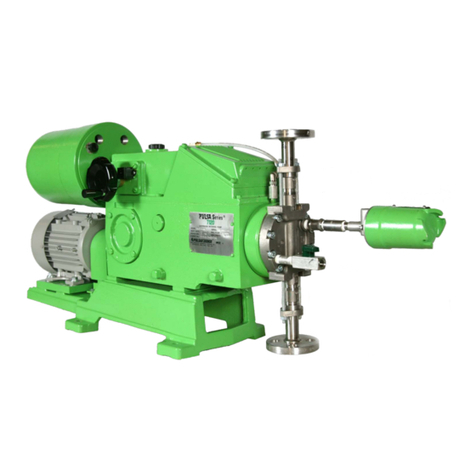
Pulsafeeder ELMA NEMA 4X Instruction manual

i
ELMA®
CONTROLLER
IOM-CTL-ELMA-2008 REV A
Installation, Operation &
Maintenance Manual
Stroke Length Controller

ii
Table of Contents
ATTENTION: RECALIBRATION OF THIS ELECTRONIC ACTUATOR IS REQUIRED...............................................1
OPERATIONAL NOTICE..........................................................................................................................1
1. MODEL CODE BREAKDOWN ..................................................................................................................2
2. INTRODUCTION .....................................................................................................................................3
2.1 General Description ................................................................................................................3
2.2 Standard Features...................................................................................................................3
2.3 Optional Features....................................................................................................................4
3. PRINCIPALS OF OPERATION ..................................................................................................................5
3.1 Basic Actuator .........................................................................................................................5
3.2 Features....................................................................................................................................6
3.3 Options.....................................................................................................................................6
4. INSTALLATION ......................................................................................................................................7
4.1 Check Model Number..............................................................................................................7
4.2 Wiring Instructions..................................................................................................................7
5. CALIBRATION .......................................................................................................................................8
5.1 Mechanical Stops....................................................................................................................8
5.2 Comparator Circuit..................................................................................................................8
5.3 Deadband .................................................................................................................................10
5.4 Meter Readout..........................................................................................................................10
5.5 Ratio Control............................................................................................................................11
5.6 Pneumatic Input.......................................................................................................................11
5.7 Protection Circuitry.................................................................................................................11
5.8 Connection Diagram ...............................................................................................................14
5.9 Trouble Shooting.....................................................................................................................14
5.10 Repairs .....................................................................................................................................15
6. SPECIFICATIONS ...................................................................................................................................19
7. DRAWINGS19
7.1 NEMA Type 4X Cross Section................................................................................................20
7.2 NEMA Type 4X Exploded Isometric.......................................................................................21
7.3 NEMA Type 7 Cross Section ..................................................................................................22
7.4 NEMA Type 7 Exploded Isometric .........................................................................................23
Revision History:
Rev A 1/25/2019 Brand update

1
ATTENTION
Recalibration of this electronic actuator is
required.
1. Although calibrated before leaving the factory, variations in input signals will
require recalibration prior to start-up. Refer to the Calibration Section of this
manual for complete instructions.
2. This actuator is equipped with signal protection circuitry. Recalibration will require
changing the setting of the DIP switches which are a part of the protection
system. Refer to the Protection Circuitry Section of this manual for complete
instructions.
OPERATIONAL NOTICE
The ELMA electronic stroke actuator is designed to function only when the pump is
operational. To ensure proper adjustment of pump stroke length, the actuator should
operate only when the pump motor is also operating. Control systems should be
designed to ensure that the actuator does not operate to change stroke set point
when the pump is not operating. This can be accomplished by:
1. Removing power from the actuator when the pump motor is turned off.
2. Removing the mA input signal from the actuator when the pump motor is turned
off, and setting the signal protection option to "freeze at last setting on loss of
signal" as per table 1, page 12.

2
1. Model Code Breakdown
Selecting an ELMA Model Number (e.g. BEMDA-BP)
1
2
3
4
5
Pump Size
Actuator Type
Input Signal
Action
Power Requirement
B = 680
E = NEMA Type 4X
C = 10-50 mA
D = Direct Action
A = 115 V, 60 Hz
C = 880
W = NEMA Type 7
D = 1-5 mA
R = Reverse Action
C = 220 V, 50 Hz
D = 200
Z = Special
M = 4-20 mA6
V = 1-5 V dc
P = 3-15 psi
NEMA 4 only5
S = Split Range
(50%; 4-20 or
12-20 mA)
X = No Auto
Signal
Z =Special
Some input signals and operations options are no longer available; contact your sales representative if you have
questions.
6 OPERATOR STATION OPTIONS
(For Customer Mounting and Wiring)
A Manual Potentiometer (Follows pump mounted potentiometer signal only) (3)
B Manual Potentiometer w/Meter Readout (1)(3)(5)
C Auto-Manual (2)
D Auto-Manual w/Meter Readout (1)(2)(5)
E Ratio Control
F Ratio Control w/Meter Readout (2)(7)
G Ratio Control w/Meter Readout and Auto-Manual (2)(3)(7)
H Ratio Control w/Auto Manual (3)
X No Option (Straight Automatic)
Z Special
7 OPERATOR STATION ENCLOSURES
H NEMA 4X Stainless Rain/Moisture Tight/Corrosive Resistant Pump Mounted (7)
J NEMA 4X Plastic Rain/Moisture Tight/Corrosive Resistant Pump Mounted (7)
P NEMA 4X Plastic Rain/Moisture Tight/Corrosion Resistant (7)
S NEMA 4X Stainless Rain/Moisture Tight/Corrosion Resistant (Outdoor) (7)
X No enclosure, Components only
Z Special
Notes:
1. For split range jobs, the order must specify whether the lower (e.g., 4-12 mA) or
upper (3.g. 12-20mA) signal portion range is required, and also whether reverse
action is needed. A very common application for this feature is for acid or alkali

3
injection in response to a pH signal for neutralization jobs, where the lower range
signal requires reverse action.
2. Meter readout is for direct acting only.
3. Auto-manual includes auto-manual switch and manual potentiometer; switch is
non- shorting type.
4. Option A and 8 in position 6 require Position 3 =X (no auto signal)
5. 3-15 psi option not available on NEMA Type 7 actuators
6. Option M also includes 4-20 mA output as standard.
7. Operator station options with meter readout (Position 8, D, F or G) are only
available in NEMA Type 4X plastic enclosure (Position 7 - J or P). Meter is
located inside the enclosure behind transparent cover. Meter does not have a
NEMA rating.
2. Introduction
2.1 General Description
The PULSA stroke length controller is an electromechanical control device which
adjusts the output flow of a PULSA Series pump according to and external process
control signal. The controller design provides a compact, integral to the pump servo
amplifier configuration, which utilizes AC synchronous motor technology as the
primary driver. The stroke length is linear and proportional (directly or indirectly, as
chosen by the customer) to the input control signal. Likewise, the reference feedback
signal which is provided for remote monitoring of actual stroke length position, is also
linear and proportional. Control of stroke length can be done manually by using the
electronic override switch and a hand knob. An external mechanical indicator is
mounted directly on the controller to indicate percent of stroke length.
2.2 Standard Features
1. Input signals
a. 4-20 mA @ 250 ohm
b. 1-5 mA @1,000 ohm
c. 10-50 mA @100 ohm
d. 1-5 VDC
2. 4-20 mA feedback output signal
3. External stroke length indicator (mechanical)
4. Manual override provision (mechanical)
5. NEMA Type 4X or UL listed NEMA Type 7 enclosure design
6. Integral actuator/servo amp design
7. Signal loss detection circuitry
8. 115 V @ 60 Hz operation
9. Over signal protection

4
10. The input and output signals are isolated from the power supply only
2.3 Optional Features
1. 3-15 PSI input signal @ 0 C.F.M.
2. Variable ratio control
3. Reverse acting control (e.g., 4 mA = 100%, 20 mA = 0%).
4. Split-ranging
5. 220 volt @ 50 Hz operation.
6. Specials - consult the factory for your special application.

5
3. Principals of Operation
3.1 Basic Actuator
The ELMA, (Electronic Lost Motion Actuator) is a simple control system composed of
a position sensing device, an electronic circuit and a mechanical interface. The
position sensor determines the actual stroke length, while the circuitry determines
whether to increase, decrease or remain the same, and the mechanical interface
actually performs the work of changing stroke length.
The stroke length of a PULSA Series pump is determined by adjusting a screw. This
screw (referred to as the adjusting shaft) has a travel of 10 turns over the span of
stroke length. In the ELMA design, an AC synchronous motor is coupled to this
adjusting shaft through a timing belt and gears, and is the means of adjusting stroke
length.
Also connected to the adjusting shaft is a potentiometer which acts as a position
sensing device. This potentiometer is mechanically coupled to the adjusting shaft via
gears and a timing belt, and is limited to 10 turns. This limit is done mechanically by
an adjustable collar and a stop on the adjusting shaft. The feedback potentiometer
provides a voltage to the circuit board which corresponds to actual stroke length.
The main function of the circuit board is to compare two analog signals to each other,
and to determine whether to increase, decrease, or keep the same stroke length.
The two analog signals come from the feedback potentiometer and from an external
instrument. (Examples of this include flowmeters, pH meters, rheostats, and
computers). The comparison dictates whether the two signals are greater than, less
than, or equal, and turns on a mechanical relay to make the AC synchronous motor
turn clockwise, counterclockwise, or stop.
The most common input signal is a 4-20 mA current signal. In order to compare
"apples to apples", this current needs to be converted to a voltage so the circuit
board can compare it to the voltage signal provided by the feedback potentiometer.
This is done by a 250 ohm shunt resistor, which converts 4-20 mA to a 1-5 volt
signal. A 1-5 volt input signal can also be used by clipping this connection to the
shunt resistor (Refer to Table 2 on Page 18}. The voltage signal from the feedback
potentiometer is adjustable through the "High Cal" and "Low Cal" trims, so that the
feedback voltages and the input voltages are of comparable voltage magnitudes.

6
TABLE 2
Signal Input Selection (Jumpers)
Input
Terminals
J4
J5
J6
J7
1-5 V
1 & 3
Out
1-5 mA
1 & 2
Out
Out
In
In
4-20 mA
1 & 2
Out
In
Out
In
10-50 mA
1 & 2
In
Out
Out
In
Remote
Auto Manual
Out
3.2 Features
Current Output Signal
A 4-20 mA output signal is provided for remote monitoring of stroke length. This
signal is generated by a voltage to current converter which is driven directly by the
feedback potentiometer. This source can drive an impedance of up to 250 ohms. The
ranges of the current outputs are adjustable on the circuit board by adjusting the zero
and span trim potentiometers.
Manual Override
By moving the manual override switch to the manual position, stroke length control
can be accomplished by hand turning the micrometer knob.
Signal Loss Detection
The circuit board can be configured suck that if a loss of input signal occurs, it will
maintain the stroke length at the position of the last given signal or drive the stroke
length to zero.
Over Signal Protection
The circuit board disregards out-of-rang signals which can lead to problems with
over-driving.
NEMA Type 7
UL Listed enclosure for Class 1, Groups C & D
3.3 Options
Pneumatic Input Signal
This option allows the use of a 3-15 PSI pneumatic input signal to control stroke
length. An integral pressure transducer converts the pneumatic signal to a 1-5 V
voltage signal, thus controlling stroke length.
Ratio Control
This option establishes a "ratio" between the input signal and resulting stroke length.
This ratio can range from 100%:100% to 100%:0%. The ratio is infinitely adjustable
over this range by adjusting a remote potentiometer.

7
Split Ranging
The split-ranging option provides full actuator response over one half the input signal
range. Response can be set for the lower or upper half of the signal range and can
be direct or reverse acting.
4. Installation
4.1 Check Model Number
Check the ELMA model number breakdown for proper power supply connection. The
model number, as well as the pump serial number, should be referred to for locating
the proper wiring diagram, parts list and installation drawings. Theis information will
describe the various options with which your electric actuator, and the pump have
been supplied and show you where to make external connections for power, signal
and other control options.
4.2 Wiring Instructions
It is important that AC power for the ELMA unit be delivered in a separate conduit
from the process signal or wiring for optional accessories. A separately switched,
and protected circuit is recommended for the actuator power supply. Wiring the
actuator in parallel with other devices (i.e. pump motor) can result in damage to the
circuitry.
Remove the actuator cover, which is held on by seven screws, or screwed on as on
NEMA Type 7, to expose the actuator wiring connection terminals. There are three
#18 gauge wires provided for the AC power connection. These wires, approximately
12” long, are color coded for ease of installation. An in-line fuse is provided for
protection.
NOTE: Explosion proof actuators are Under Writers Laboratories (UL) listed
and are labeled with the hazardous environments for which they are rated,
along with any special installation specifications required in support of UL
listing. They must be installed, wired, operated, and maintained in accordance
with local electrical codes.

8
5. Calibration
Before shipment, all actuators are calibrated to provide proper response to the
input signal specified at the time of order. However, after installation, it is
recommended that the unit be re-calibrated to compensate for any difference
between factory and field conditions.
Run the signal and accessory wiring using the second conduit fitting. A 22 AWG wire
size or larger is recommended. Twisted and shield conductors can do much to
reduce noise problems. Make all connections as per the diagram that applies to the
combination of signal and accessories provided. Leave the actuator cover off for
calibration.
5.1 Mechanical Stops
Figures 1 & 7
1. Loosen setscrews on front and rear mechanical stops
2. Turning worm shaft, position crosshead at full forward extension
3. Thread adjustment shaft up to piston leaving a gap between the piston and
crosshead of 0.002 inches.
4. Slide front mechanical stop forward until it is tight against the gearbox wall.
Secure in place with setscrews.
5. Note position of dial counter. Turn adjustment shaft clockwise 10 times.
6. Slide rear mechanical stop back against buishing. Secure in place with
setscrews.
7. Loosen knob and duo-dial.
8. Reset dial to 10 and secure with setscrews.
NOTE: Pumps with stroke length of 0.375” will need 7.5 on the dial at 100%
stroke setting
9. Position knob lining up long marks on knob with numbers on dial. Secure in place
with setscrews
10. With override switch in manual position, rotate adjustment shaft to 0% stroke and
then to 100% stroke. This will position the feedback potentiometer to allow
calibration of ELMA.
5.2 Comparator Circuit
See Figures 3, 4, and 5
Calibration
If equipped with pneumatic input, refer to that section of calibration. If equipped with
ratio control use one of the following procedures but perform all adjustments at 100%
ratio setting.
1. Comparator calibration procedure to be used with units supplied for AUTO
control from a remote process signal.
a. With the override toggle switch in the “MAN” position wire the actuator per the
supplied wiring diagram
b. Locate the negative lead of a voltmeter to TB1-1 and the positive lead to TB1-3

9
c. With the voltmeter in the DC mode, measure and record the voltage across
TB-1 and TB-3 at 0% and 100% process signal
d. Remove the process signal from the board
e. Manually adjust the micrometer hand knob to 0% stroke setting
f. Locate the positive lead of the voltmeter to the wiper terminal (black lead) of
the feedback potentiometer while the negative lead is on TB1-1. Adjust the
“Low Cal” potentiometer so that the wiper voltage equals that read in Step C
at 0% process signal.
g. Manually turn the hand knob to the 100% setting and adjust the “High Cal”
trim potentiometer so that the wiper voltage now equals that read in Step C at
100% process signal.
h. Repeat Steps f and g until the voltage from the feedback wiper and stabilized
to match the respective voltages read from Step C.
i. Reconnect the process signal and place the override toggle switch to Auto
position. Verify proper operation. If the actuator fails to fully adjust to either
endpoint or does not switch off, then readjust the “Low” or “High Cal” trim
potentiometer depending on which endpoint is off, until proper adjustment is
achieved.
Remote Auto/Manual Calibration
2. Comparator calibration procedure to be used with units supplied for MANUAL
control from a remote manual potentiometer or units supplied for AUTO/MANUAL
control from a remote process signal and remote manual potentiometer.
a. With the override toggle switch in the "man" position wire the actuator and
remote enclosure per the supplied wiring diagram.
b. For AUTO/MANUAL units turn the remote control switch to the "auto"
position.
c. Perform steps b-i as outlined in Procedure 1). For MANUAL units substitute a
signal generator in place of the process signal.
d. Place both the override toggle i switch and remote control switch in the' "man"
position.
e. With the manual stroke adjustment potentiometer at 0% measure the voltage
across TB1-1 and TB1-3. Adjust the "Low" trim potentiometer on the back of
the remote potentiometer assembly until the measured voltage equals that
measured in Step 1-c at 0% process signal.
f. Turn the manual stroke adjustment potentiometer to 100%. Now adjust the
"High" trim potentiometer on the back of the potentiometer assembly until the
voltage across the TB1-1 and TB1-3 equals that measured in step 1-c at
100% process signal.
g. Repeat steps e and f until the measured voltages are stabilized to match the
respective voltages read from step 1-c.
h. Place the override toggle switch in the “auto” position. Verify proper operation
of the controller through the stroke adjustment potentiometer. If the actuator
fails to fully adjust to either endpoint or reaches one endpoint and does not
switch off, then readjust the “Low” or “High” trim potentiometer on the back of
the potentiometer assembly depending on which endpoint is off, until proper
adjustment is achieved.

10
5.3 Deadband
See figures 3 & 4
Adjustment of the deadband determines how closely the comparator circuit will
attempt to match the feedback signal to the input signal. It provides a “window” of
acceptable voltage tolerances.
Example
If the deadband is too loose the comparator circuit is not as sensitive to signal
change and may not fully adjust to the change of an input signal.
If the deadband is too tight the comparator circuit may constantly “hunt” causing
erratic actuator movement with no change to the input signal.
Deadband adjustments are preset at the factory. If adjustments to the deadband
have been unsuccessful you can go back to factory preset by turning the trim
potentiometer screw ten times (CCW) “counter-clockwise” then one turn (CW)
clockwise.”
5.4 Meter Readout
See figures 3 & 4
a. Put proper load and/or meter across TB1-7 as (+) and with TB1-8 as (-),
for a 4-20 mA signal.
b. With the micrometer hand knob at 0%, adjust the zero adjust so that 4 mA
is output from the circuit and/or meter reads minimum.
c. With the micrometer hand knob at 100% adjust the span adjust so that 20
mA is output from the circuit and/or meter reads maximum.

11
d. Repeat steps b and c until 4-20 mA is output from the circuit when 0%
and 100% is dialed in and/or meter reads minimum and maximum.
5.5 Ratio Control
Due to highly tolerance components, no adjustment is necessary.
5.6 Pneumatic Input
See figure 5
a. With the override toggle switch in the “man” position, wire the actuator per
the supplied wiring diagram.
b. Connect the negative lead of a voltmeter to TB1-1. This point is a circuit
board common.
c. Locate the positive lead of a voltmeter to J6 of the option board.
d. Input a 3 psi signal into the ¼” NPT port and adjust the zero adjust until a
1 volt reading is obtained.
e. Input a 15 psi input and adjust the span adjust on the option board until a
5 volt reading is obtained.
f. Repeat steps d and e until a 1-5 volt reading is obtained.
g. Remove the pneumatic signal from the board and place the override
toggle switch in the “remote” position.
h. Located the positive lead of the voltmeter to the wiper terminal (black
lead) of the feedback potentiometer.
i. With the micrometer hand knob at the 0% stroke setting adjust the “low
Cal” trim potentiometer until a 1 volt reading is obtained.
j. Turn the knob to the 100% setting and adjust the “High Cal” trim
potentiometer until a 5 volt reading is obtained.
k. Repeat steps I and j until the voltages from the feedback wiper stabilize at
1 and 5 volts.
l. Reconnect the pneumatic signal and place the override toggle switch to
auto. Verify pr4oper operation. If the actuator fails to fully adjust to either
endpoint and does not switch off then readjust the “Low” or “High Cal”
trim potentiometer depending on which endpoint is off, until proper
adjustment is achieved.
5.7 Protection Circuitry
The signal protection circuitry determines how the actuator responds in the event of
a loss of signal or over signal condition. Once the unit has been calibrated to a
specific input signal it recognizes any signal which is less than the calibrated low end
signal as a loss of signal and any signal greater than the calibrated high end signal
as an over signal. Responses are determined by the setting of the 3 position DIP

12
switch (see Fig. 3). During calibration the circuit may see under or over signals and
therefore the protection feature must be turned off for proper adjustments to be
made. Table 1 illustrates how the DIP switch settings relate to the different nodes.
Re-calibration will require changing the setting of the dip switches to the open
position (refer to Table 1, Function 1).
Table 1
DIP Switch Settings (figure 3)
Switch Position
Function
S1
S2
S3
1. Calibration mode, protection disabled
Open
Open
Open
2. Drive to zero on loss signal
Closed
Open
3. Freeze at last setting on loss of signal
Open
Closed
4. Over signal protection
Closed
Note:
1. If both S1 and S2 are closed, Function 3 will be active.
2. ‘_’ signifies switch can be in either position for that function.
3. Set switches by depressing the appropriate side with a straightened paper
clip or similar object. Depressing side marked “OPEN” will open the switch,
depressing the other side will close it.

13

14
5.8 Connection Diagram
Since the hydraulic oil system is primed at the factory, priming the process system is
all that should be necessary to produce flow. If the hydraulic system has
inadvertently been dumped due to start up with restricted suction or discharge
conditions or improper adjustments to compensator or bleed valves, repriming
procedures under the maintenance section may have to be followed before pump
calibration can begin.
5.9 Trouble Shooting
Problem
Probable Cause
Actuator does not adjust
1. No AC power to actuator
2. Pump not running
3. Override switch no in Auto position
4. Control signal off, incorrect, or of inverted polarity
5. Ratio control (if so equipped) set at or very near
zero percent
6. Blown fuse
7. Wiring discontinuity
8. Defective feedback potentiometer (see repairs)
9. Circuit board malfunction
10. Broken drive belt
Actuator adjusts to incorrect settings
1. Control signal incorrect or of inverted polarity
2. Incorrect ratio control setting (if so equipped)
3. Circuit board out of calibration (see “Calibration”)
4. Meter readout out of calibration (if so equipped)
(See “Calibration)
5. Actuator misaligned to pump (See “Repairs”
6. Defective feedback potentiometer (See “Repairs”)
7. Circuit board malfunction
Actuator adjust in one direction only
1. Control signal incorrect or of inverted polarity
2. Incorrect ratio control setting (if so equipped)
3. Wiring discontinuity
4. Defective feedback potentiometer (See “Repairs”)
5. Circuit board malfunction
Erratic operation
1. Wiring discontinuity
2. Narrow deadband (See “Calibration”)
3. Erratic control signal (See “Deadband”)
4. Noisy control signal (check grounding and
shielding of control signal leads)
5. Defective feedback potentiometer (See “Repairs”)
6. Circuit board malfunction

15
5.10 Repairs
Potentiometer
1. Remove P3 connector from circuit board
2. Verify full potentiometer resistance of approximately 1,000 ohms between pins 2
and 3.
3. A needle type (analog) meter is recommended for checking potentiometer
operation. As the potentiometer gear is turned counter clockwise (as seen from
the gear end), the resistance between pins 1 and 2 should vary uniformly from
zero to approximately 1,000 ohms.
As the potentiometer gear is turned clockwise (as seen from the gear end), the
resistance should vary uniformly from approximately 1,000 ohms to zero.
4. If the extreme readings vary significantly from zero to 1,000 ohms respectively or
if the resistance variation with rotation is not smooth at any point, the
potentiometer should be replaced. If the directions of rotation are the reverse of
those stated above, then the potentiometer has been wired for reverse acting
operation.
5. To replace the potentiometer assembly, pre-set the pump stroke indicator to the
“050” (50%) setting. Use a meter as described above to set the resistance of the
potentiometer to 500 ohms, which represents mid-scale.
6. Install the potentiometer carefully without rotating or changing the position.
Reconnect P3 to the circuit board.
Zero Adjust on Duo Dial
See “Mechanical Stops,” pages 5 and 6
Conversions
To convert a manual control 200, 680, or 880 pump to ELMA control, the following
assemblies are required:
1. Convert kit and actuator
2. Option kit as required
a. Ratio control option – W208946-000
b. Pressure Control Option – W208947-001 (for NEMA Type 4X actuator only)
c. Pressure Control with Ratio Option – WE208947-002 (for NEMA 4X actuator only)
d. Split Range Control Option – W209725-001
Check to make sure you have the appropriate assemblies before beginning the
conversion.
Note: Loosely tighten screws. Perform final tighten during mechanism
adjustment unless otherwise specified.
Removal of Manual Control
1. Remove cover and drain gearbox
2. Unthread nut, sleeve and jam nut. Unthread the adjustment shaft and pull out
from gearbox. Note: Adjustment shaft is left handed.
3. Carefully pull barrel indicator and bushing off at gearbox if not removed in step 2.
4. Remove reagent head assembly, pump head assembly and cross head (Models
200 and 680 only) from gearbox
5. Remove pump from base
6. If the adjustment shaft hole diameter in the gearbox measures 0.625 + 000/0.001
proceed to “Preparing Gearbox for ELMA Mounting”

16
Machining Gearbox
1. With table indicated perpendicular to machining head clamp gearbox to table with
head end down.
2. With indicator, locate machining head to center od adjustment shaft hold in
gearbox
3. Bore adjustment shaft hold, to 0.625 +000/0.001” diameter
4. For Model 880 gearboxes, inside spotface must be 1.00” diameter. (Optional
1.00 wide mill cut centered on adjustment shaft hole acceptable.
Preparing Gearbox for ELMA Mounting (Figures 7 & 8)
1. Press bushing into gearbox with flange to in the inside. Note: Insert O-ring in
bushing before pressing into gearbox
2. Feed adjustment shaft through bushing into gearbox, threaded end first
3. Slide rear mechanical stop onto adjustment shaft. See Fig. 7 Place 2 #8-32
screws 90 degrees apart prior to assembly
4. Slide front mechanism stop onto adjustment shaft. (Place 2 #8-32 setscrews 90
degrees apart prior to assembly).
5. Thread adjustment shaft into gearbox Note: Adjustment shaft is left handed
6. Slide adjustment shaft extension over adjustment shaft and into bushing
7. For NEMA Type 7, skip to “Assembly of ELMA Control”
8. Locate template provided over shaft extension and worm shaft. Mark 4 mounting
hole centers. (Note: There are eight holes in template. Only use 4 holes
indicating in Fig. 8 for model pump being converted)
9. Remove template. Drill and tap #10-32UNF-2B through at locations marked in
sept 7
10. Flush gearbox to remove all chips from inside gearbox
Conversion Kit
Pump Model
Assembly Number
200, 680
W210294-680
880
W210294-880
Actuator Assembly
Model Stroke Cycles
Actuator Assembly
Number NEMA Type 4X
Actuator Assembly
Number NEMA Type 7
680 AE
3/8
60 Hz
W210210-001
W210502-001
680 AE
3/8
50 Hz
W210210-003
W210502-003
680 AE
½
60 Hz
W210210-000
W210502-000
680 AE
½
50 Hz
W210210-002
W210502-002
680 AP
3/8
60 Hz
W210234-001
680 AP
½
60 Hz
W210234-000
680 AP
½
50 Hz
W210234-002
880 AE
5/8
60 Hz
W210210-000
W210502-000
880 AE
5/9
50 Hz
W210210-002
W210502-002
880 AP
5/8
60 Hz
W210234-000
880 AP
5/8
50 Hz
W210234-002

17
Assembly of ELMA Control
1. Reinstall crosshead, pump head and reagent head assembly
2. Holding rear mechanical stop against bushing, push adjustment shaft extension
forward until it hits the stop. Slide nylon washer, over shaft extension. Slide
timing gear over shaft extension forward to gearbox. Secure timing gear in place
with 2 #8-32 setscrews spaced 90 degrees apart.
3. Turning worm shaft, position crosshead at full forward extension.
4. Thread adjustment shaft up to piston leaving a gap between piston and
crosshead of 0.002 inches.
5. Slide front mechanical stop forward until it is tight against the gearbox wall.
Secure stop in place with setscrews.

18
6. Place reference marker on timing gear and gearbox. (Felt marker works best)
7. Slide rear mechanical stop back against bushing and secure in place with
setscrews.
8. Pull timing gear and shaft extension from gearbox. (Check that nylon washer
remains next to timing gear)
9. NEMA Type 4 only, apply Permatex Form-A-Gasket to the 4#10 fillester head
screws that mount ELMA bracket to gearbox. (Note: On 880 pumps, place seal
spacer washers on top 2 screws between gearbox and mounting plate). Mount
bracket to gearbox.
b. NEMA Type 7 only mount actuator and gearbox on base.
10. With nylon washer still next to timing gear, slide shaft extension back into
gearbox
11. Place second nylon washer on shaft extension against the timing gear
12. Position timing belt over gear, pinion, and adjuster as shown in Fig. 8.
13. NEMA Type 4X only, install belt guard and bracket. Space upper standoff #8 flat
washer between bracket and standoff to insure proper alignment of adjustment
shaft extension.
b. NEMA Type 7 only, install belt guard and bracket.
14. With the adjustment shaft at 100% stroke (fully retracted) set duo-dial at 10 and
mount on shaft extension. (Be sure to position locking groove in dial over roll pin
on bracket.) Secure in place with setscrew provided.
15. Mount knob on shaft extension taking care to postion long marks on knob with
numbers on dial. Secure in place with 2 #6-32 setscrews spaced approximately
90 degrees apart.
16. Mount gearbox on base.
Adjustment of ELMA Control
1. With override switch in manual position, rotate adjustment shaft to 0% stoke,
then to 100% stroke. This will position the feedback potentiometer to allow
calibration of ELMA.
2. See Section on “Calibration Instructions for Adjusting Mechanism” for adjustment
and assembly completion.
This manual suits for next models
1
Table of contents
Other Pulsafeeder Controllers manuals

Pulsafeeder
Pulsafeeder MicroVision User manual

Pulsafeeder
Pulsafeeder MicroVision EX User manual

Pulsafeeder
Pulsafeeder MicroVision EX User manual

Pulsafeeder
Pulsafeeder PULSAblue 3300 Series User manual

Pulsafeeder
Pulsafeeder PULSAmatic 7120 Manual

Pulsafeeder
Pulsafeeder MPC Instruction manual

Pulsafeeder
Pulsafeeder ABC 50 Manual