Furrion C-FACR15SA-A02 User manual

Heat Strip Installation Kit
Instruction Manual Model:
C-FACR15SA-A02
P
* Picture shown here is for reference only.

1
Thank you and congratulations for purchasing this Furrion product. Before operating
your new product, please read these instructions carefully. This instruction manual
contains information for safe use, installation and maintenance of the product.
Please keep this instruction manual in a safe place for future reference. This will ensure
safe use and reduce the risk of injury. Be sure to pass on this manual to new owners of
this product.
The manufacturer does not accept responsibility for any damages due to not
observing these instructions.
Table of Contents
Table of Contents ......................................................................................................... 1
Before Use..................................................................................................................... 2
What’s in the Box.................................................................................................................................... 2
Installation .................................................................................................................... 3
Operation....................................................................................................................... 6
Specifications............................................................................................................... 7

2
What’s in the Box
Make sure the unit and the accessories are in the box. If anything damaged or missing,
contact your dealer.
Component Description Quantity
Model C-FACR15SA-A02
Heat Strip 1
Screw ST4x9 mm 4
Washer Ø4*Ø9*0.8mm 4
“HEAT” Icon Sticker 1
Connecting Harness 1
Installation Instructions 1
Warranty Leaflet 1
NOTE: This heat strip installation kit applies to the following models of the rooftop unit
and air distribution box (ADB). Please refer to the model of your unit before installation.
−Rooftop Unit models: FACR13SA-PS, FACR13SA-BL,FACR14SA-PS,
FACR14SA-BL, FACR15SA-PS, FACR15SA-BL.
−Air Distribution Box models: FACT11MA-PS, FACT11MA-BL, FACT11CA-PS.
Before Use

3
DANGER
Electric Shock Hazard
●Disconnect power or shut off the air conditioner circuit breaker before
installation.
●Failure to do so can result in electric shock.
WARNING
Installation of the heat strip must be carried out by a professional/certificated
technician only.
Disassemble the Top Unit
1. Remove the 10 screws used to fix the
top cover, 4 on the front, 2 on each
side of air vents, and 2 on the filter
grill. (Fig. 1)
Fig. 1
2. Remove the top cover and place it on
a flat surface. (Fig. 2)
Fig. 2
Installation
3. Remove the EPP top cover of the
evaporator by pulling upwards, and
place it on a flat surface. (Fig. 3)
NOTE: The silicon sealant may retain
the cover, gently work the shroud
apart from the sealant to remove.
Silicon Sealant
EPP top cover
Fig. 3
Disassemble the Trim Kit
NOTE: The following steps are only for
retrofitting, If installing a new system, skip
to “Install the Heat Strip” section.
4. Remove the two control knobs by
pulling downwards (Fig. 4).
5. Take off the decoration plate from the
trim kit by pushing the side tabs to
release (Fig. 4).

4
Fig. 4
6. Remove the two filters by pulling the
tabs to release. (Fig. 5)
Fig. 5
7. Remove the trim kit body by
unscrewing the four screws. Leave
the metal bracket and mounting
screws attached.(Fig. 6)
Fig. 6
Install the Heat Strip
8. Align the 4 screw holes on the heat
strip with that on the evaporator, 2
holes on each side. (Fig. 7)
9. Insert four screws with washers into
these holes. And then fasten them.
(Fig. 7)
Heat Strip
Evaporator
Wire of the Heat Strip
Fig. 7
NOTE: Use ST4 x 9mm screws
(provided) only. Use of other type of
screws may pierce/damage the copper
tubing in the evaporator.
10. Fix the harnesses together with nylon
cable ties (not provided). Then pass
the 2 harnesses down through the air
intake vent to the RV (Fig. 8).
NOTE: Retain wire harnesses away
from the electric heater element and
evaporator to prevent being damaged.
Heat strip wire
Motor wire
Cable tie
Fig. 8
11. Install the EPP top cover of the
evaporator back, and ensure the pipe
outlet is sealed well with the existing
silicon sealant.
NOTE: Make sure the top cover is
aligned with the lower cover of the
evaporator when installing back.

5
12. Install the top cover of the rooftop
unit back and fasten the 10 screws
removed in step 1.
Wire Connection
DANGER
Electrical Shock Hazard
●Disconnect power before servicing.
●Failure to obey this warning could
result in death or serious injury.
13. Unscrew the 3 screws on the
electrical control box, remove the
covers and controls attached to it
(Fig. 9).
Fig. 9
14. Plug the black wire of the connecting
harness, a 3-pin terminal interface
(provided), into the “H” pin of the
switch. (Fig. 10)
Fig. 10
15. Route neutral/white wire over to the
junction box, and connect with the
other neutral/white wires. (Fig 11)
Fig. 11
White Wires
ba
16. Install and lock the 3-pin terminal
interface onto the reserved opening
on the electrical control box.(Fig. 12)
3-pin terminal
interface
Reserved
opening
Fig. 12
17. Put all wires in the control box and
then install the box covers back and
tighten the 3 screws.(Fig. 13)
Fig. 13
18. Plug
the 3-pin connector of the heat
strip into the 3-pin terminal interface
on the control box.(Fig. 14)

6
Fig. 14
19. When the heat strip is connected to
the control box, reverse above steps
to install the electrical box, refer to
your trim kit for final installation of
your AC, or reverse the steps taken to
dissemble your trim kit body.
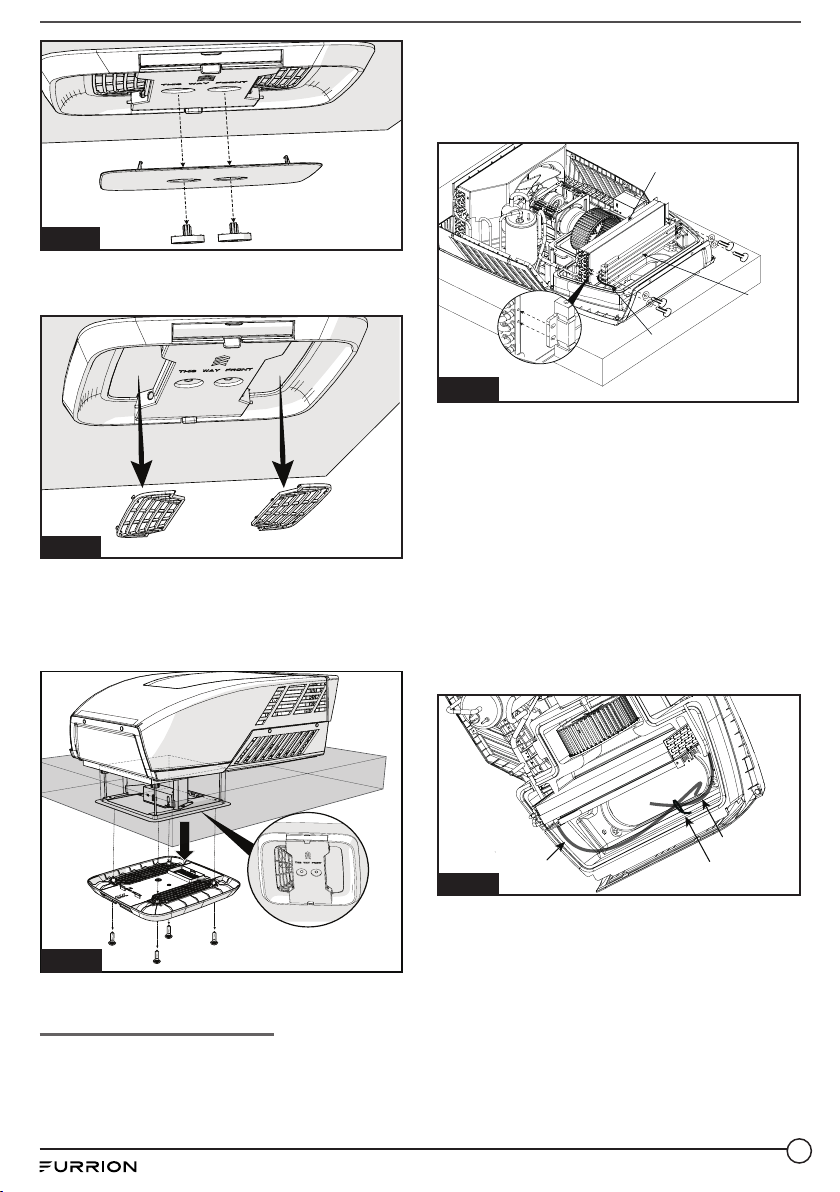
20.For the decoration plate with icon
“FAN”, cover with the provided “HEAT”
decal. (Fig. 15)
Fig. 15
For those already with silk screen
HEAT(OPTIONAL), omit this step. (Fig.16)
Fig. 16
Now the installation is completed.
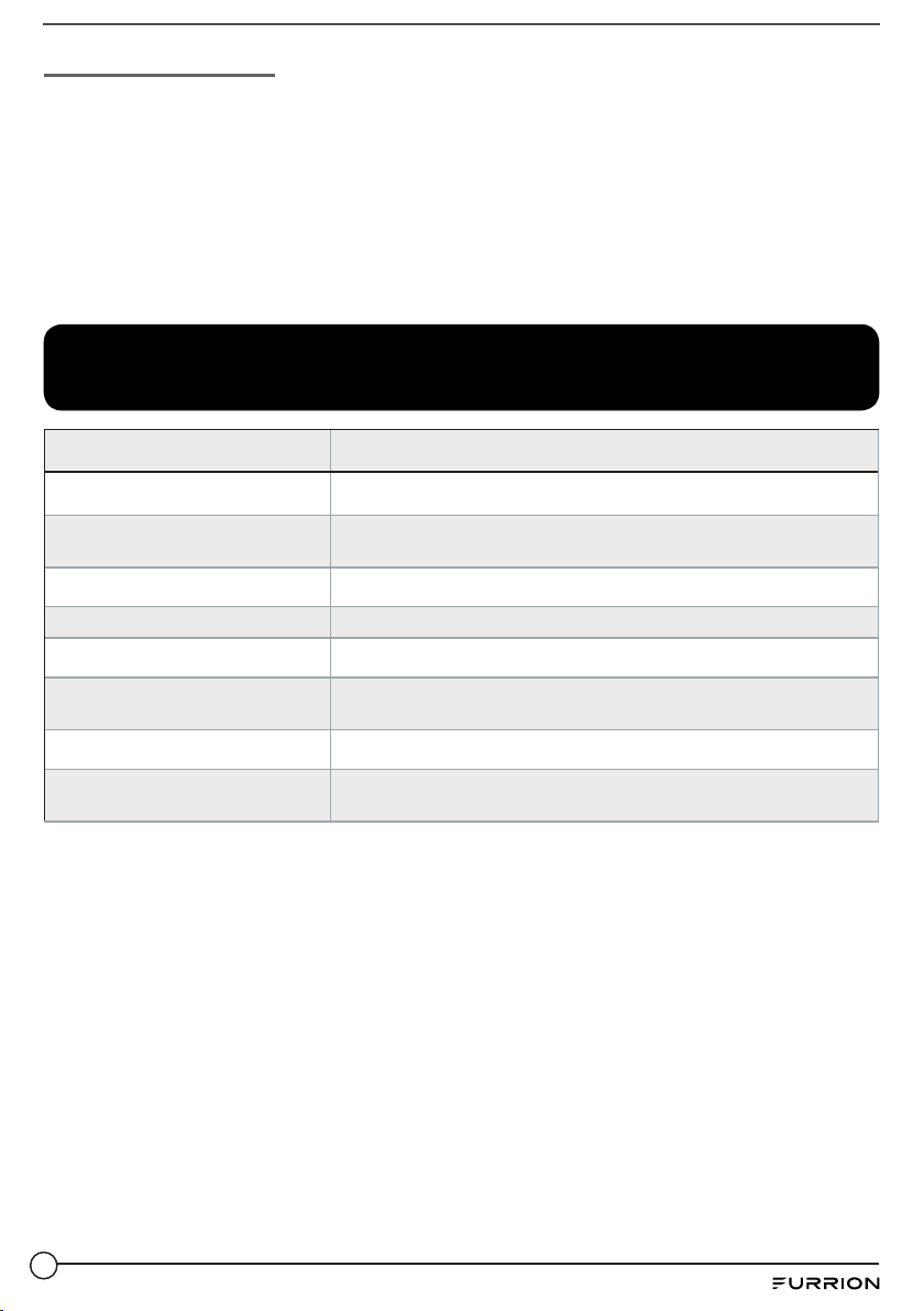
Operation
Installation of the Heat strip has created
a new “HEAT” mode with your controller.
The following will describe how to
operate. Operation of “FAN”, “COOL”
mode and “OFF” does not change,
refer to your air conditioner manual for
operation.
When to use HEAT mode?
During conditions where the ambient
temperature has dropped between 50-
70 °F, the “HEAT” mode can be utilized to
bring the temperature up to a comfort-
able level.
The Electric Heater works best in smaller
spaces, like bedrooms or isolated rooms.
NOTE: HEAT mode should not be con-
sidered a replacement to your standard
furnace, or expected to heat the entire
coach. It may need to be used in con-
junction with the furnace under extreme
conditions.
How to use it?
To activate, rotate your mode function
selector to the HEAT position.

7
How does it work?
When you want to warm the coach, turn on the HEAT mode. Once the temperature
has reached a desired condition, Manually turn the mode function selector to another
mode or “OFF” position.
Manually cycle “ON/OFF” to maintain a temperature as desired.
NOTE: The temperature selector function is not usable with HEAT mode, therefore
the control needs to be cycled manually to maintain temperature. Avoid excessively
long usage periods to prevent overheating. Consider using the furnace to bring the
temperature up first, then maintain with the HEAT mode.
Specifications
Model C-FACR15SA-A02
Heating Capacity 1,500W
Operation Ambient
Temperature 19°F~86°F (-7°C~30°C)
Volts/Hertz 115V/60Hz
Power Watts 1,500W
Power Cord Gauge AWG14 (1.6 mm)
Dimensions L 17⁄’’ x W 3⅞’’ x H ⁄’’
(L 452mm x W 98mm x H 23.5mm)
Weight 0.74kg (1.63lbs)
Safety Standard CSA/UL 60335-1, Second Edition &
CSA/UL 60335-2-40, Second Edition

Furrion Innovation Center & Institute of Technology
• 52567 Independence Ct., Elkhart, IN 46514, USA • Toll free:1-800-789-3341
©2007-2020 Furrion Ltd. Furrion®and the Furrion logo are trademarks licensed for use by Furrion Ltd. and
registered in the U.S. and other countries.
IM-FHA00075 V1.0
Table of contents
Popular Electric Heater manuals by other brands

EQUATION
EQUATION HELLA User and maintenance manual

AEG
AEG SHG 150 Operation and installation

HUUM
HUUM HIVE Installation and operation manual

TESY
TESY CN03 EIS W Operation and storage manual

Airelec
Airelec Premier Pro Installation & user guide

Dimplex
Dimplex EF12 series Installation and operating instructions