Furrion DV 7200 User manual

This drawing contains proprietary information and trade secrets of The Furrion Company, Inc.
Unauthorized use or copying is prohibited.
METRIC
[INCH]
METRIC [INCH]
CRITICAL DIMENSION
CHECKING IS COMPULSORY
VOLUME cm3
MASS grams REV. DATE MODIFICATIONS NAME ECN NO.
DENSITY g/cm3MATERIAL: The Furrion Company, Inc.
GENERAL TOLERANCES
EXCEPT AS NOTED
0 TO 6mm = ±0.1
>6 TO 30mm = ±0.2
>30 TO 80mm = ±0.3
>80 TO 180mm = ±0.4
>180mm = ±0.5
ANGULAR = ± 3°
FINISH SPEC:
COMPOSITE-NO SHEET 1 OF 1
SCALE: DATE: DRAWN BY: APPROVED BY: REVISION:
NAME: PART NO.
Instruction Manual for DV7200 Entertainment Systerm IM-FAV00033
1.0
Ricky Deng
Sally Peng XX
Sally Peng
28-May-18
V1.0 28-May-18 NEW
Printing Notes:
Material: 80 GSM Bond Paper or 50# Bond Paper White
Ink: Black
Resolution: 150 DPI or above
Printing method: Offset Printing
Binding: Saddle Stitch
Folded size: 100 x 60 mm (W x H)
DO NOT PRINT THIS PAGE

2
Entertainment System
DV 7200
Instruction Manual

1
Welcome
Thank you for purchasing this Furrion®Entertainment System. Before placing your new product
into operation, please read these operating instructions carefully. They contain important
information for safe use, installation and maintenance of the product.
Please keep this instruction manual in a safe place for future reference. Pass it onto possible new
owners of the product. The manufacturer does not accept responsibility for any damages that may
arise due to non-observation of these instructions.
If you have any further questions regarding our products, please contact us at

2
Contents
Welcome...............................................................................................1
Contents ...............................................................................................2
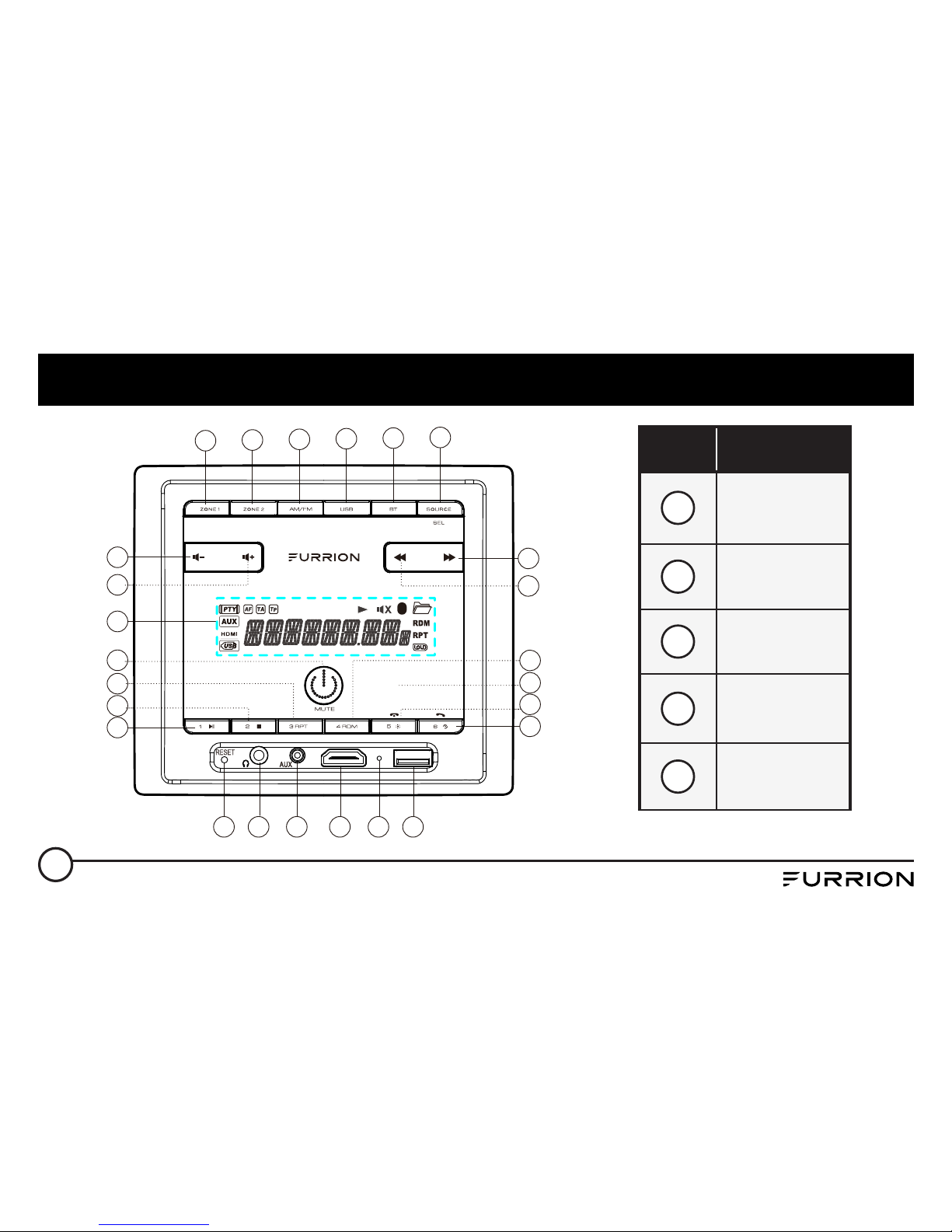
Locations and Names of the Controls ...................................................3
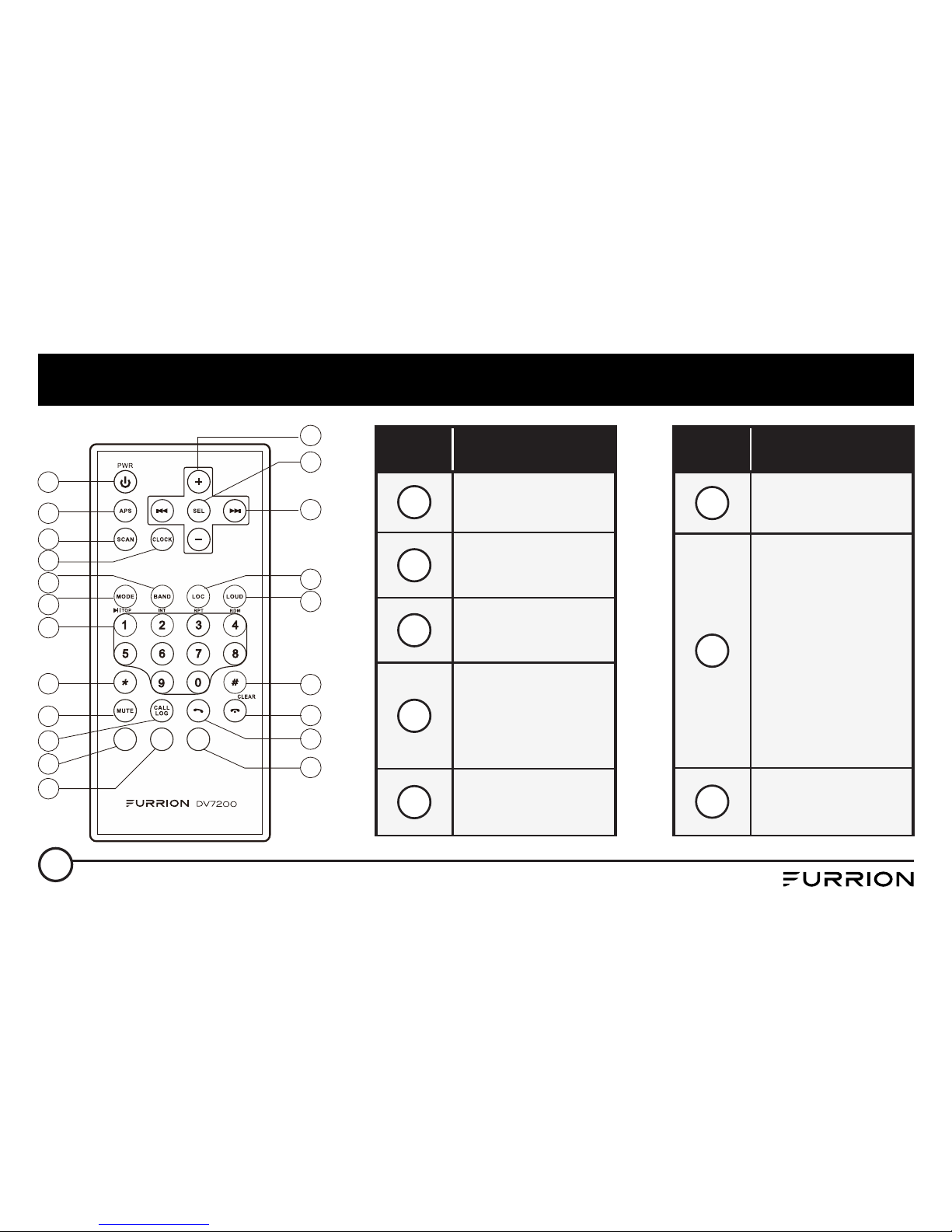
Remote Control ....................................................................................5
Installation ...........................................................................................7
Connections..........................................................................................9
Operation............................................................................................ 14
Common Operation .........................................................................14
Radio Operation...............................................................................17
USB Operation .................................................................................18
Bluetooth Operation ........................................................................20
Specification ....................................................................................... 24
Warranty............................................................................................. 26

3
Locations and Names of the Controls
19 20 21 22 23 24
4
14
15
1
3
2
13 18
11
12
17
16
25
5 6 7 8 9 10
Item Button
1Power &
Mute
2LCD Display
3Volume +
4Volume -
5ZONE 1

4
Locations and Names of the Controls
Item Button
6ZONE 2
7AM/FM
8USB
9BT
10 SOURCE/
SEL
Item Button
11 Next
12 Previous
13 1/Play/
Pause
14 2/STOP
15 3/RPT
Item Button
16 4/RDM
17
5/Backlight/
Hang up
18
6/Clock Adjust/
Alarm/TEL
19 RESET
20 Headphone
Socket
Item Button
21 Aux In Jack
22 HDMI In
Jack
23 Microphone
24 USB Socket
25
NFC Detection
Area

5
Remote Control
Z ONE1
AL ARM Z ONE2
1
3
4
5
2
6
7
8
9
10
14
15
13
16
17
18
11
21
12
19
20
Item Button
1POWER
2APS
3SCAN
4CLOCK
5BAND
Item Button
6MODE
7
Number(0-9)
1/ PLAY/
PAUSE
/TOP Button
2/INT Button
3/RPT Button
4/RDM Button
8* Button

6
Remote Control
Item Button
9MUTE
10 CALL LOG
11 TEL
12 HANG UP
13 # Button
Item Button
14 LOUD
15 LOCAL
16 UP & DOWN
17 SEL
18 + & -
Item Button
19 ALARM
20 ZONE 1
21 ZONE 2

7
Installation
Location
●Choose a mounting location away from humid areas, water sources, burning products or any
equipment that can radiate heat.
●Select an area on the wall or cabinet, which is free from cable, fuel or brake lines. There is a
vent hole at the back of the unit for cooling purpose, do not block it.
●Ensure when the stereo is mounted in the cut out that the wires at the rear of the unit are not
pressed against the heat sink.
Installing the unit
●Before finally installing the unit, connect the wiring temporarily and make sure the unit and the
system can work properly.
●Fix the unit to the wall using 4 self-tapping screw as indicated in the illustration.

8
Installation
Screw
Screw
Plastic frame of
the front panel
1. Remove plastic frame of the
front panel from the unit.
2. Fix the unit to the wall with
4 #8 pan head self-tapping
screw.
3. Replace the plastic frame of
the front panel to the unit.

9
Connections
Supported Audio Format
File Extension .mp3 .wma
Audio Code MP3 WMA
Bit Rate 16kbps - 320kbps CBR/VBR 16kbps - 320kbps
Sampling
Rate 8k - 48kHz 8k - 48kHz
Remark / WMA only support WMA7/WMA8/WMA9/
(CBR/VBR)(only support 353 format)
NOTE: Reading the above file formats is not guaranteed.

10
Connections
Wiring Diagram
HDMI OUT JACK
AV IN
AV OUT
IR REMOTE JACK
SUBWOOFER OUT
WIRING CONNECTING SOCKET
ANTENNA
AUDIO IN

11
Connections
Wiring connecting socket view
1
2
3
4
5 7
6 8
Item Color Function
1Green Zone 2 Left Speaker(+)
2Purple/
Black Zone 2 Right Speaker(-)
3White Zone 1 Left Speaker(+)
4Gray/
Black Zone 1 Right Speaker(-)
5
Gray Zone 1 Right Speaker(+)
White/
Black Zone 1 Left Speaker(-)

12
Connections
NOTE: All speakers must be connected as
shown. If one wire is removed or not connected
properly, all speakers on relevant zone will fail
to work. It is of importance to pay attention in
speaker polarity. Connection with incorrect
speaker polarity will lead to poor sound quality.
Item Color Function
6
Purple Zone 2 Right Speaker(+)
Green/
Black Zone 2 Left Speaker(-)
7Red +12V DC
8Black Power Ground

13
Connections
WHITE(+)
GRAY/BLACK(-)
GRAY
WHITE/BLACK
GREEN(+)
PURPLE/BLACK(-)
PURPLE
GREEN/BLACK
ZONE 1
LEFT
ZONE 1
LEFT
ZONE 1
RIGHT
LEAVE NOT
CONNECTED
ZONE 2
LEFT
ZONE 2
LEFT
ZONE 2
LEFT
LEAVE NOT
CONNECTED
4-Speaker (2 ZONE) Wiring 2-Speaker Mono (2 ZONE) Wiring
WHITE
ZONE 1 LEFT SPEAKER(+)
WHITE/BLACK
ZONE 1 LEFT SPEAKER(-)
GRAY
ZONE 1 RIGHT SPEAKER(+)
GRAY/BLACK
ZONE 1 RIGHT SPEAKER(-)
GREEN
ZONE 2 LEFT SPEAKER(+)
GREEN/BLACK
ZONE 2 LEFT SPEAKER(-)
PURPLE
ZONE 2 RIGHT SPEAKER(+)
PURPLE/BLACK
ZONE 2 RIGHT SPEAKER(-)

14
Operation
Common Operation
1. To turn the unit On/Off
When the unit is powered Off, it may be switched On by pressing the POWER button. When the
unit is switched On, press and hold the POWER button to switch if off.
2. To select the function mode
Press AM/FM, USB, BT button on the front panel to select the corresponding mode.
Press SOURCE button repeatedly on the front panel to select HDMI, AUX, AV mode.
3. To adjust the volume level
During playback, press VOLUME+ or VOLUME- button on the front panel to increase or
decrease the volume.
4. To mute or resume the sound
During playback, press MUTE button on the front panel to mute or resume the sound
immediately.
5. To check speaker output status and select speaker output
Short-press ZONE 1 or ZONE 2 button on the front panel to check the speaker output status.
Press and hold ZONE 1 or ZONE 2 button on the front panel to turn on/off the corresponding
speaker output, “Z 1 ON/OFF” or “Z 2 ON/OFF” will be displayed on the LCD.
6. To set the sound mode and menu

15
Operation
Press and hold SEL button to turn on BASS, then press SEL button repeatedly to select or
circulate through TRE (treble), EQ OFF (FLAT/...AMERICA3/AUSTRALIA/EUROPE (in radio
mode), press VOLUME+/- to change the settings. Press SEL button to confirm your selection.
–1) BEEP ON/BEEP OFF
BEEP ON mode: The beep is generated when any key is pressed.
BEEP OFF mode: The beep sound is disabled.
–2) VOL LAST/VOL DEFA
VOL LAST: The last volume level setting will be saved automatically after switched the unit
off, and restored after powered on.
VOL DEFA: Press SEL button on the front control panel, the AVOL mark will be displayed on
LCD. Use VOLUME+/- to set the volume level as a constant value.
–3) DX/LOCAL
In Radio mode, with the DX/LOCAL selection you can change the attenuator settings at the
input stage of the radio. This selection helps to avoid overloading the radio when strong
(local) stations are received. Select DX (distant) mode to receive far / weak radio stations
(highest sensitivity settings are enabled) and select LOCAL for very strong stations (which are
located nearby).

16
Operation
(NOTE: This button is only for FM reception. In AM mode, LOC is invalid.)
7. To display and adjust the time
Press and hold 6 button until the clock becomes flashing. Use VOLUME+/- button to adjust the
hour, and / button to adjust the minute.
8. To adjust the backlight brightness
Press and hold 5/BACKLIGHT button repeatedly to adjust the backlight.
9. Alarm Function
–1) To turn On/Off the alarm mode
Press 6button repeatedly to enter the alarm setting mode. (Use VOLUME +/- button to select
ALARM ON or ALARM OFF)
–2) To set the ALARM time
Press and hold the 6button repeatedly to ALARM time setting mode (the LCD will display the
time “AM 00’00“ ), then use the / button to set the MINUTE and VOLUME +/- button to
set the HOUR.
10.To reset the unit
–1) Press RESET button with a cuspidal object. The unit will be reseted to factory default
settings.

17
Operation
–2) In AUX mode, press and hold 2/STOP button until the LCD displays “RESET III”, then press
and hold 3/RPT button to reset to the factory default settings.
Radio Operation
1. To select radio band
Press AM/FM button repeatedly to select a desired radio band in sequence and circulating as:
-->FM1-->FM2-->FM3-->AM1-->AM2-->.
2. To search for radio station manually or automatically
–In radio mode, press / button to search your desired radio stations up/down manually.
–Press and hold / button to search for the strongest station up/down automatically.
3. To store current station or turn on a preset one
–1) If you want to store the current station, press and hold AM/FM button until the frequency
flashes, press one of the digit buttons from 1~6 to store the current station in the preset
memory bank. In this way the unit can store 30 preset stations.
–2) Press one of the 6 buttons from 1~6 to enter the preset station in current band.
4. To auto search and store the top 6 strongest stations
In radio mode, press and hold 2/STOP button on the front panel, the unit will start to search the

18
Operation
available stations and check the signal strength from the lowest frequency. The top 6 strongest
stations will be saved to the corresponding preset numbered band 1~6.
5. To set the frequency
Press and hold SEL button to turn on BASS, then press SEL button repeatedly to select
AMERICA3, AUSTRALIA or EUROPE area, press VOLUME+/- button to select your desired
frequency. Press SEL button to confirm your selection.
USB Operation
1. To insert or pull out the USB stick
To play the tracks in USB disk, insert the USB disk into the USB port. The playing mode will be
changed to USB mode automatically and the USB mark will be displayed on LCD.
2. Press or button to play previous or next track.
3. To play fast forward or backward
Press and hold or button to play backward or fast forward, release to resume normal
playback.
4. To play previous or next 10th track.
Press 5 or 6 button to play previous or next 10th track.
5. How to use 1/PLAY/PAUSE button
Table of contents
Other Furrion Stereo System manuals