manuals.online logo
Brands
  1. Home
  2. •
  3. Brands
  4. •
  5. Furse
  6. •
  7. Surge Protector
  8. •
  9. Furse ESP SL06 User manual

Furse ESP SL06 User manual

Technical Help
is available from:
Thomas & Betts Limited
Furse
Wilford Road
Nottingham
NG2 1EB
United Kingdom
Tel: +44 (0)115 964 3700
Fax: +44 (0)115 986 0538
www.furse.com
Installation Instructions
For in-line data-line protectors
ESP SL06, ESP SL15, ESP SL30,
ESP SL50, ESP SL110, ESP SL15X,
ESP SL30X, ESP SL TN, ESP SLR TD
Earthing (continued)
In extreme cases where even 4m of connecting
lead is not sufficient, the incoming line should be
re-routed to bring it within 4m of the earth.
If the line cannot be re-routed; the Lightning
Barrier can, as a last resort, be connected to
the electrical earth local to the equipment
being protected.
Keep clean lines away from dirty lines
Cables connected to the Lightning Barrier’s clean
end should never be routed next to dirty line
cables or dirty barrier earth bonds. See Figure 7.
If rows of Lightning Barriers are installed close to
each other, dirty (‘line’) lines and earth bonds
must be kept at least 5cm apart from ‘clean’ lines.
See Figure 8.
Note: When using the DIN rail foot to
provide the Earth to the Lightning Barrier in
conjunction with a base plate (i.e. DIN rail
not directly bonded onto cabinet chassis)
ensure the earth bond to the base plate (or
DIN rail itself) is kept clear of the ‘clean’
lines.
Maintenance/Spares
In the unlikely event of a failure, replacement
modules are available, contact sales on
+44 (0)115 964 3700.
If a replacement module is required please
quote part number with a suffix /M
e.g. a replacement module for an ESP SL30 barrier
would be ESP SL30/M.
ESP Lightning Barriers contain no user
serviceable parts and must be replaced with
equivalent genuine Furse modules.
The modules can easily be removed by pressing in
the release button and pulling the module away
from the base. The module is keyed to prevent it
being inserted the wrong way around.
Insulation/Flash testing
The ESP Lightning Barriers can be easily
disconnected from the system for insulation
testing. When the module is 1cm away from
being fully inserted there is a 2nd hold point.
Instead of completely removing the module and
having to record which point it is required to be
replaced in, this point allows the module to be
held in place within the base but disconnected
from the system’s wiring.
General information
In common with all other electrical apparatus
installed in hazardous areas, the Lightning Barriers
must only be installed, operated and maintained
by competent personnel. The ESP SL**X Series
have a group IIC T4 certification making it
acceptable for use with all gas/air mixtures.
Location
Field instrument protection should take place in
Zone 1 and as close as practically possible to the
Zone 0 boundary, preferably within 1m to prevent
transient voltages from entering Zone 0. Ensure
the Lightning Barriers are mounted on a separate
DIN rail to the IS Barriers. See figure 9. Ideally, the
Lightning Barrier should be installed within the
housing of the field instrument, however due to
space restrictions it may be necessary to mount
the unit in a suitable enclosure available from
Furse.
Installation
The Lightning Barrier must not be subjected to
thermal and/or mechanical stresses in excess of
those permitted in the certification
documentation, see product datasheet. If
necessary the product must be protected by an
enclosure to prevent mechanical damage as the
Lightning Barrier requires additional protection for
use in dust environments.
The Lightning Barrier must not be installed in
a location where it may be attacked by
aggressive substances and must be protected from
excessive dust, moisture and other contaminants
by an enclosure.
Inspection and Maintenance
Inspection and maintenance should be carried out
in accordance with European, national and local
regulations which may refer to the IEC standard
IEC 60079-17. In addition specific industries or
end users may have specific requirements which
should also be met.
If the outer enclosure of the Lightning Barrier
needs to be cleaned, this should be done with a
cloth lightly moistened by a dilute mixture of
detergent in water.
Conditions for safe use
The plastic enclosure must not be rubbed in
service as it may present an electrostatic risk.
When the surge protection module is fitted, the
range of SL**X Series Surge Protection Devices
will not meet the 500V insulation requirements to
earth. Please refer to Installation - Section 8,
Insulation/Flash testing, for information of how to
disconnect the module for insulation testing.
ESP SL**X barriers provide surge protection
on the Intrinsically safe (IS) circuits only and
do not replace the IS barrier itself.
Marking
The specific ATEX certification and ratings are
clearly marked on the product label for each of
the ESP SL**X Lightning Barriers. In addition there
is a separate label on both the replaceable
module and base housing to indicate the
manufacturing date.
2
1
6
5
4
3
8
7
6
SAFETY NOTE:
1. Always handle cables by their insulation
2. Never work on Lightning Barriers or their
cables during a storm
© Copyright Thomas&Betts 2010
ESP SL06, ESP SL15, ESP SL30, ESP SL50, ESP SL110,
ESP SL15X, ESP SL30X, ESP SL TN, ESP SL RTD
✗
LINE CLEAN
ESP SL06
✓
LINE CLEAN
ESP SL06
L
I
N
E
C
L
E
A
N
L
I
N
E
C
L
E
A
N
ESPSL06S
ESPSL06S
ESPSL06S
ESPSL06S
ESPSL06S
ESPSL06S
ESPSL06S
ESPSL06S
ESPSL06S
ESPSL06S
ESPSL06S
ESPSL06S
ESPSL06S
ESPSL06S
ESPSL06S
ESPSL06S
ESPSL06S
ESPSL06S
ESPSL06S
ESPSL06S
ESPSL06S
ESPSL06S
ESPSL06S
ESPSL06S
Figure 7 - Cable routeing
Figure 8 - Positioning of adjacent rows of
Lightning Barriers
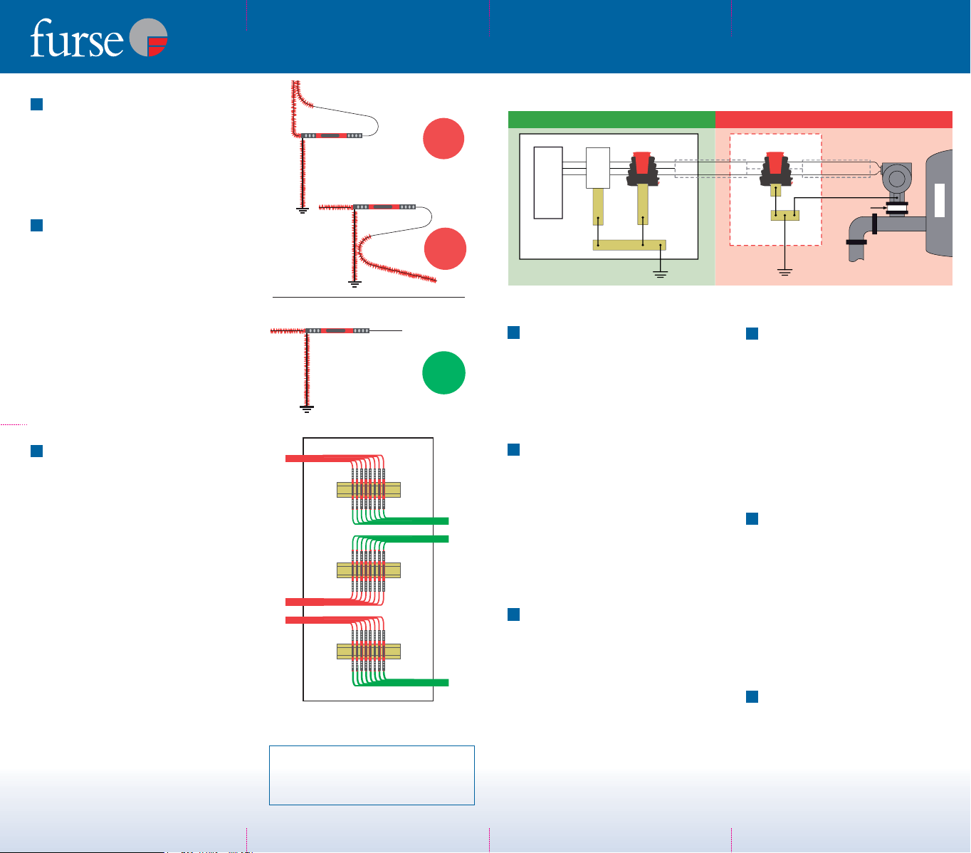
Figure 9 - The ESP SL**X Series can provide protection for the PLC or RTU I/O as well as providing protection
for the IS barrier. The isolated screen (ESP SL**X/I) version should be used in zone 1, 2.
Instrumentation
Instrument
Earth
ESP SL30X/I
ESP SL30X
Control cabinet
IP54
enclosure
Instrument
Earth
System
Earth
Field
earth
Open end cable screen
ZONE 0
Hazardous AreaZones 1,2Non-Hazardous Area
Isolated
coupling
IS
Barrier
Intrinsically safe barriers for Hazardous areas - ESP SL**X only
LINE CLEAN
ESP SL06
✗
TNB 2059 ESP Instructions v2:Layout 1 25/2/10 16:51 Page 1
Introduction
This document explains
how to install Furse
Electronic Systems
Protectors for twisted
pair data communication/
signal/telephone lines:
ESP SL06
ESP SL15
ESP SL30
ESP SL50
ESP SL110
ESP SL RTD
ESP SL TN
And Surge Protectors for
Intrinsically Safe Areas:
ESP SL15X
ESP SL30X
Before installation
Current rating
Ensure that the current passing through the
Lightning Barrier does not exceed:
Current Rating
ESP SL** 750mA
ESP SL**X 750mA
ESP SL RTD 300mA
ESP SL TN 300mA
Working voltage
Make sure that the system’s maximum line
voltage (DC or AC peak) will never exceed the
maximum working voltage of the Lightning
Barrier. Otherwise the Lightning Barrier will
clamp signal voltages as though they were
transient overvoltages.
Normal Maximum
working working
Voltage Voltage
ESP SL06 6V 7.79V
ESP SL15 15V 16.7V
ESP SL30 30V 36.7V
ESP SL50 50V 56.7V
ESP SL110 110V 132V
ESP SL RTD 6V 7.79V
ESP SL TN 296V 296V
Line resistance
Check that the voltage drop caused by the
resistance of the unit does not interfere with the
normal operation of the system.
Line Resistance
ESP SL** 1.0Ω
ESP SL**X 1.0Ω
ESP SL RTD 1.0Ω
ESP SL TN 4.4Ω
Bandwidth
Be sure that the Lightning Barrier’s bandwidth will
not restrict the system bandwidth.
Bandwidth (-3dB)
ESP 06 1.5MHz
ESP SL15 - ESP SL110 >85MHz
ESP SL**X >85MHz
ESP RTD 800kHz
ESP TN 20.0MHz
Installation
Location
Lightning Barriers are usually located either:
(a) Near to where the lines requiring protection
enter or leave the building, or
(b) Close to the equipment being protected
(or actually within its control panel).
Either way, it is important that the Barrier’s
connection to earth (or barrier earth bond) is kept
short. See Section 6 - Earthing.
Enclose the Lightning Barrier
Lightning Barriers should be installed within a
panel or enclosure.
The Lightning Barrier should be ideally
installed within an existing cabinet/ cubicle or
in an enclosure to the required IP rating.
Suitable enclosures are available from Furse.
Lightning Barriers should always be installed in
a dry environment.
Series connection
Furse ESP Lightning Barriers are connected in-line
(or series) with the data communication, signal,
measurement, or telephone line. See Figures 1a
and 1b. The dirty, or line side of the protector
should be connected to the cable carrying the
incoming transient overvoltages. The output or
clean side of the protector ensures a transient free
signal to the equipment being protected.
Fixing methods
Furse ESP Lightning Barriers should be mounted
on 35mm DIN rail to EN 50022. See Figure 2.
The ESP Lightning Barriers DIN rail release clip
features a latch back mechanism to hold the clip
off the rail for easy removal and adjustment whilst
on the DIN rail. This release clip should be
engaged using a terminal screw driver or by hand
by pulling the clip out and upwards in the
housing. See Figures 3a and 3b.
Connections to line, clean, screen
and earth terminals
The clean end of the Lightning Barrier should be
connected to the cabling going to the protected
equipment. See Figures 1a and 1b.
Cable screens are connected to Earth (DIN rail and
Earth terminal) via the terminals marked S, except
the ESP SL RTD where the screen could be
connected to the Earth terminal marked .
The screw terminals should be tightened between
0.5 - 1Nm torque (Do not exceed 1Nm).
For isolated screens
For situations where the cable screen needs to be
isolated from the local Earth to avoid Earth loops
(e.g. Fire alarm panels) the isolated screen version
should be used (this has /I suffix in the part code
e.g. ESP SL30/I). With the isolated screen
version there is no continuity between the
Screen and Earth connections in the absence
of a transient overvoltage.
The screw terminals will accommodate conductor
of up to 4mm2. We recommend that these are
terminated with a boot lace ferrule
.
Earthing
Protectors for mains power supplies and Lightning
Barriers for data/signal/telephone lines should be
connected to the same earth point.
The Lightning Barrier should therefore be bonded
to the main electrical earth or earth star point.
This connection should be made, either:
(a) Through installation on a 35mm DIN rail
(which in turn is connected to earth).
(b) By connecting a earth cable to the barrier
via the Barriers Earth terminal marked .
See Figure 1a and 1b.
The best way to ensure a good earth connection
when using a DIN rail is to mount the DIN rail in a
metal cabinet. The entire length of the DIN rail
should be in contact with the metal of the cabinet
(if the cabinet is painted this should be removed
locally where the rail is to be mounted to give a
good electrical connection). The DIN rail should
then be bonded to the cabinet at its mounting
points and the chassis of the cabinet bonded to
the main electrical earth or earth star point.
Alternatively if a non-metal housing is used the
DIN rail should be bonded to a metal base plate.
The base plate should then be bonded to the
earth star point.
The barrier or base plate earth bond should be
less than 1m long (otherwise the effectiveness of
the protector will be reduced).
10mm2stranded green/yellow cable should be
used for this bond.
Barrier or base plate earth bonds of 2, 3 or 4m
are allowed if; 2, 3 or 4 parallel earth bonds are
used and these parallel earth bonds are kept at
least 5cm apart from each other.
...continued overleaf
6
5
4
3
2
1
4
2
3
1
WARNING: Incorrect
installation will impair the
effectiveness of the ESP units
Figure 1a – Series connection of ESP SL** Series,
ESP SL**X Series and ESP SL TN.
Figure 2 – Installation on 35mm DIN rail. Figure 3a – Slide out the DIN rail release clip.
1
S
2
3
S
4
Lightning Barrier
From line
LINE CLEAN
Earth
To equipment
Furse
Wilford Road,
Nottingham,
NG2 1EB, UK
Clean
Line
30V
37.8V
750mA
1.0
10kA
43.5V
Nominalvoltage
Maxworkingvoltage,
Current rating
In-line resistance
Maxs urgecurre nt
Let- through v oltage, U
Figure 3b – Pull up and release to engage the
latchback mechanism.
Figure 1b – Series connection of ESP SL RTD.
1
2
3
4
5
6
Lightning Barrier
From line
LINE CLEAN
Earth
To equipment
Furse
Wilford Road,
Nottingham,
NG2 1EB, UK
Clean
Line
30V
37.8V
750mA
1.0
10kA
43.5V
Nominalvoltage
Maxworkingvoltage,
Current rating
In-line resistance
Maxs urgecurre nt
Let- through v oltage, U
ESP SL06, ESP SL15, ESP SL30, ESP SL50, ESP SL110,
ESP SL15X, ESP SL30X, ESP SL TN, ESP SL RTD
TNB 2059 ESP Instructions v2:Layout 1 25/2/10 16:51 Page 2
Thank you for reading this data sheet.
For pricing or for further information, please contact us at our UK Office, using the details
below.
UK Office
Keison Products,
P.O. Box 2124, Chelmsford, Essex, CM1 3UP, Engl nd.
Tel: +44 (0)330 088 0560
F x: +44 (0)1245 808399
Em il: s [email protected]
Please note - Product designs and specifications are sub ect to change without notice. The user is responsible for determining the
suitability of this product.

This manual suits for next models

8

Popular Surge Protector manuals by other brands

AETEK SD-101 Quick installation guide

AETEK

AETEK SD-101 Quick installation guide

Philips SPN5087C/10 user manual

Philips

Philips SPN5087C/10 user manual

Philips SPP2306WC Specifications

Philips

Philips SPP2306WC Specifications

nvent ERICO SES360 Series instruction sheet

nvent

nvent ERICO SES360 Series instruction sheet

Belkin F7C01008 user guide

Belkin

Belkin F7C01008 user guide

Bretford MPP-15 Product information

Bretford

Bretford MPP-15 Product information

UTP BALUN SP-BNC user manual

UTP BALUN

UTP BALUN SP-BNC user manual

Rocket Fish RF-PCS12ES13 Guía De Instalación Rápida

Rocket Fish

Rocket Fish RF-PCS12ES13 Guía De Instalación Rápida

Powerware NetSurge Plus instruction manual

Powerware

Powerware NetSurge Plus instruction manual

Total Protection Solutions 80 Operation manual

Total Protection Solutions

Total Protection Solutions 80 Operation manual

QVS PP150 Specifications

QVS

QVS PP150 Specifications

Savio LZ-11 user manual

Savio

Savio LZ-11 user manual

Panamax MOD-AT2 instructions

Panamax

Panamax MOD-AT2 instructions

Emerson SOLAHD STCPOE65FF quick start guide

Emerson

Emerson SOLAHD STCPOE65FF quick start guide

Progressive Industries SSP Series operating guide

Progressive Industries

Progressive Industries SSP Series operating guide

Panamax MFP-400 instructions

Panamax

Panamax MFP-400 instructions

Opal ACZ563 instruction manual

Opal

Opal ACZ563 instruction manual

Transtector ALPU Series installation instructions

Transtector

Transtector ALPU Series installation instructions

manuals.online logo
manuals.online logoBrands
  • About & Mission
  • Contact us
  • Privacy Policy
  • Terms and Conditions

Copyright 2025 Manuals.Online. All Rights Reserved.