Furuno 9ZWFM8800S User manual

VHF RADIOTELEPHONE
FM-8800D/8800S

Your Local Agent/DealerYour Local Agent/Dealer
9-52 Ashihara-cho,9-52 Ashihara-cho,
Nishinomi
y
a 662-8580, JAPANNishinomi
y
a 662-8580, JAPAN
Tele
p
hone :Tele
p
hone : 0798-65-21110798-65-2111
FaxFax 0798-65-42000798-65-4200
::
F
IRST EDITION :
F
IRST EDITION : SEPSEP.. 20042004
Printed in JapanPrinted in Japan
A
ll ri
g
hts reserved.
A
ll ri
g
hts reserved. A1A1 :: SEPSEP.. 22, 200422, 2004
Pub. No.Pub. No. OME-56420OME-56420
*
00014993000
*
*
00014993000
*
*
00014993000
*
*
00014993000
*
(( TATATATA )) FM-8800D/SFM-8800D/S * 0 0 0 1 4 9 9 3 0 0 0 ** 0 0 0 1 4 9 9 3 0 0 0 *
*
OME
56420
A
10
*
*
OME
56420
A
10
*
*
OME
56420
A
10
*
*
OME
56420
A
10
*
* O M E 5 6 4 2 0 A 1 0 ** O M E 5 6 4 2 0 A 1 0 *

i
CANCELING DISTRESS ALERT
If less than three seconds has elapsed since the [DISTRESS] key was pressed,
the distress alert may be canceled by pressing the [CANCEL] key. Otherwise, do
the following:
1. Switch off equipment immediately.
2. Switch equipment on and set to Channel 16.
3. Transmit message to “All Stations” giving your vessel's name, callsign and
DSC number to cancel the distress alert.
Example message:
All Stations,All Stations,All Stations
This is VESSEL'S NAME, CALLSIGN,
DSC NUMBER, POSITION.
Cancel my distress alert of
DATE, TIME, UTC.
=Master, VESSEL'S NAME, CALLSIGN.
DSC NUMBER, DATE, TIME UTC.

ii
SAFETY INSTRUCTIONS
Do not disassemble or modify the
equipment.
Fire, electrical shock or serious injury
can result.
Turn off the power immediately if water
Do not open the equipment.
leaks into the equipment or the equip-
ment is emitting smoke or fire.
Continued use of the equipment can cause
fire or electrical shock.
Do not place liquid-filled containers on
the top of the equipment.
Fire or electrical shock can result if a
liquid spills into the equipment.
Any repair work must be done by a
licensed radio technician.
Improper repair work can cause electrical
shock or fire.
Do not operate the equipment with wet
hands.
Electrical shock can result.
Keep heater away from equipment.
Heat can alter equipment shape and melt
the power cord, which can cause fire or
electrical shock.
Hazardous voltage which can
cause electrical shock, burn
or serious injury exists inside
the equipment. Only qualified
personnel should work inside
the equipment.
WARNINGWARNING
CAUTION
Do not touch any part of the antenna
when the equipment is transmitting.
Electrical shock can result.
Use the proper fuse.
Use of a wrong fuse can result in fire or
cause permanent damage to the equipment.
WARNING
To avoid electrical shock, do not
remove cover. No user-serviceable
parts inside.
Terminal, Communication
Unit
Name: Warning Label (1)
Type: 86-003-1011
Code No.: 100-236-231
Do not approach the antenna
closer than 33 cm when it
is transmitting.
The antenna emits radio waves
which can be harmful to the
human body.
WARNINGWARNING
FM-8800S
RF power density
on antenna aperture distance
100 W/m20.11 m
10 W/m20.33 m
FM-8800D 100 W/m20.10 m
10 W/m20.33 m

iii
TABLE OF CONTENTS
FOREWORD .........................................................................................................v
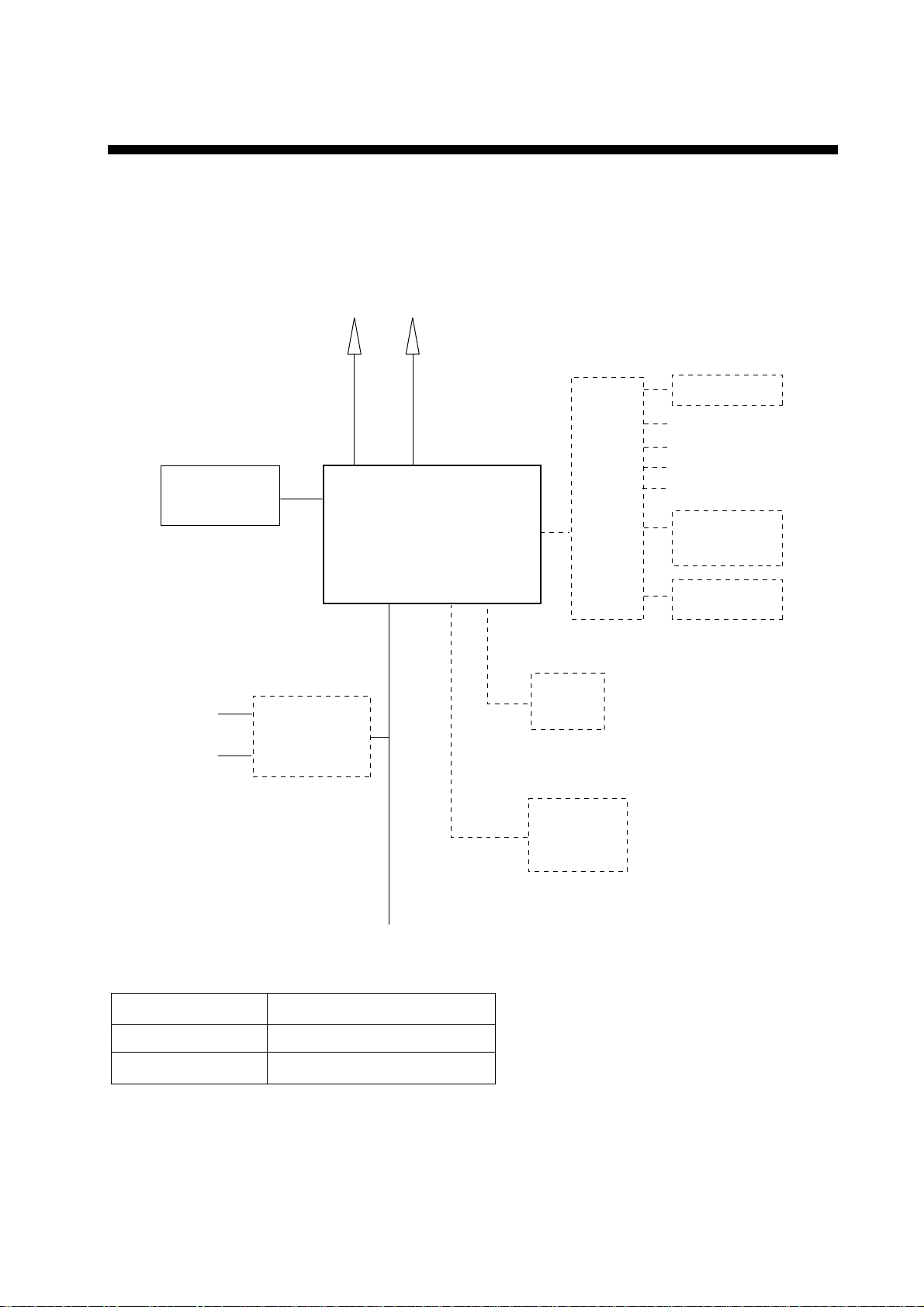
SYSTEM CONFIGURATION............................................................................... vii
SPECIFICATIONS...........................................................................................SP-1
1. OPERATIONAL OVERVIEW
1.1 Controls Keys and LCD Indication .............................................................................1-1
1.2 VHF Basic Operation.................................................................................................1-7
1.3 DSC Operational Overview......................................................................................1-10
1.4 Priority.....................................................................................................................1-12
2. DSC DISTRESS COMMUNICATION
2.1 DistressAlert Transmission from the DISTRESS Key................................................2-1
2.2 DistressAlert Transmission with Nature of Distress ...................................................2-3
2.3 Distress Alert Transmission From CALL Key..............................................................2-4
2.4 Canceling a False Distress Alert ................................................................................2-6
2.5 Receiving DistressAlert from Other Vessel, Transmitting DISTACK Signal...............2-6
2.6 Sending Distress Relay on Behalf of a Ship in Distress ........................................... 2-11
2.7 Receiving Distress Relay.........................................................................................2-15
3. DSC OPERATION FOR NON-DISTRESS CASES
3.1 Coast or Ship Call......................................................................................................3-1
3.2 Group Call...............................................................................................................3-10
3.3 PSTN Call................................................................................................................3-13
3.4 All Ships Call............................................................................................................3-16
3.5 GeographicalArea Call............................................................................................3-19
3.6 Position Call.............................................................................................................3-22
3.7 Polling Call...............................................................................................................3-25
3.8 Neutral Craft Call.....................................................................................................3-29
3.9 Medical Transport Call.............................................................................................3-30
3.10 Log File....................................................................................................................3-32
4. BASIC SETUP
4.1 Alarm Setup...............................................................................................................4-1
4.2 Auto ACK Setup.........................................................................................................4-3
4.3 Erasing Logs..............................................................................................................4-5
4.4 Memory Channel Setup.............................................................................................4-6
4.5 Message File Entry....................................................................................................4-7
4.6 Position Setup.......................................................................................................... 4-11
4.7 Print Out Setup........................................................................................................4-12
4.8 Volume Setup..........................................................................................................4-13

TABLE OF CONTENTS
i
v
5. SYSTEM SETUP
5.1 Displaying Self ID...................................................................................................... 5-1
5.2 Displaying Group ID LIST.......................................................................................... 5-1
5.3 Naming Intercom....................................................................................................... 5-2
5.4 Displaying Program Version...................................................................................... 5-3
6. MAINTENANCE & TROUBLESHOOTING
6.1 Maintenance.............................................................................................................. 6-1
6.2 Troubleshooting......................................................................................................... 6-1
6.3 Daily Test................................................................................................................... 6-2
6.4 Error Message........................................................................................................... 6-3
6.5 Parts Location........................................................................................................... 6-3
APPENDIX ......................................................................................................AP-1
Menu Tree.......................................................................................................................AP-1
Marine VHF Channel Lists...............................................................................................AP-3
Digital Interface (IEC 61162-1 Edition 2)........................................................................AP-14

v
FOREWORD
A Word to FM-8800D/FM-8800S Owners
Congratulations on your choice of the FURUNO FM-8800D/FM-8800S VHF
Radiotelephone. We are confident you will see why the FURUNO name has
become synonymous with quality and reliability.
For over 50 years FURUNO Electric Company has enjoyed an enviable
reputation for quality marine electronics equipment. This dedication to
excellence is furthered by our extensive global network of agents and dealers.
This equipment is designed and constructed to meet the rigorous demands of
the marine environment. However, no machine can perform its intended function
unless operated and maintained properly. Please carefully read and follow the
recommended procedures for operation and maintenance.
We would appreciate hearing from you, the end-user, about whether we are
achieving our purposes.
Thank you for considering and purchasing FURUNO equipment.

FOREWORD
vi
Features
The FURUNO FM-8800D/FM-8800S is a cost-effective all-in-one marine VHF
radio system consisting of a 25 W VHF radiotelephone, a DSC modem, and a
CH 70 watch receiver. It complies with GMDSS carriage requirements for safety
and general communications.
The FM-8800D offers full-duplex voice communications and the FM-8800S
offers simplex voice communication on ITU channels in the marine mobile VHF
band. The features include Dual Watch which allows a continuous watch on
CH16 and another selected frequency.
Full Class-A DSC functions are provided for distress alert transmission and
reception, as well as the general call formats (Individual telephone, All Ships,
Group and Area Call). Distress alert can be readily transmitted but an
arrangement is provided to prevent accidental activation. The FM-8800D/
FM-8800S maintains a continuous watch on CH70 even while another VHF
channel is in use.Aural and visual alarms are given to incoming DSC messages.
The main features of the FM-8800D/FM-8800S are
• Compact cabinet allows for flexible and space-saving installation on a
navigation console or at the conning position
• Conforms to the following standards and regulations:
IMO A.694(17)
IMO A.803(19)
IMO A.524(13)
IMO MSC 68(68), MSC/Circ.862
IEC61097-3/7/8
IEC60945 (4th edition)
IEC61162-1 (July 2000)
ETS 300 338, 300 698, 301 925
ITU-R M.493-10, M.541-8, M.689-2
• Full-duplex communications: FM-8800D
• Precision PLLfrequency synthesizer for high frequency stability as required for
DSC operation
• Dual Watch and Multiple Watch
• Continuous DSC watch on CH70
• Prevention of accidental distress alert
• File editing for emergency readiness
• Automatic entry of own ship position with manual override
Program number
FM-8800D/FM-8800S:0550215-02

vii
SYSTEM CONFIGURATION
The FM-8800D/FM-8800S is a highly advanced 25 W VHF transceiver with DSC
terminal. It is designed to satisfy the stringent requirements of marine
communications, and complies with GMDSS carriage requirements for safety
and general communications.
TRANSCEIVER UNIT
FM-8800D
FM-8800S
Handset
HS-2003
VHF
Antenna CH 70 RX
Antenna
AC/DC
Power Supply
Unit
PR-240-CE
100/220 VAC
50/60 Hz, 1φ
Category of units
Antenna
All other units
Exposed to weather
Protected from weather
Category
Radio Battery
24 VDC
24 VDC
Junction
Box
IF-8810 Remote box
RB-
8800/8810
HS-8800
Printer
PP-510
External
Speaker
SEM-21Q
DMC I/F
IF-8820
Wing handset
T/R AF output for VDR
MAX
2 sets
MAX
4 sets
IEC61162-1 input
DSC information output
Unit
External alarm
FM-8800D/FM-8800S system configuration

viii
This page is intentionally left blank.

SP-1
SPECIFICATIONS OF MARINE VHF RADIOTELEPHONE
FM-8800D/FM-8800S
1. GENERAL
(1) Number of Channels INTL: 57
USA: 55 (57)*
Weather: 10
Canada:55(57)*
INLND-WA: 55 (57)*
Private: 20 *: CH75&76 can be included
MEMORYCH:50 forsomecountries.
(2) Frequency Stability Within ±1.5 kHz
(3) Communication System FM-8800S: Simplex/Semi-duplex
FM-8800D: Simplex/Full-duplex
(4) Class of Emission 16K0G3E (Voice)
16K0G2B (DSC)
(5)Antenna Impedance 50 ohms
2. TRANSMITTER
(1) Frequency Range
(2) Output Power 25 W max., 1 W at power reduction
(3) Frequency Deviation <5 kHz
3. RECEIVER
(1) Frequency Range
(2) Receiving System Double Superheterodyne
(3) Intermediate Frequency 1st: 51.2375 MHz, 2nd: 37.5 kHz
(4) Sensitivity +6 dBµV (20 dB SINAD)
(5)Adjacent Channel Selectivity 70 dB or more
(6) Spurious Response 70 dB or more
(7)AF Output Built-in Speaker: 3 W (4 ohms)
Handset earphone: 2mW (150 ohms)
4. DSC
(1) Protocol ITU-R Rec. 541-8, 493-10 (classA)
(2) Baud Rate 1200 baud ±30 ppm max.
(3) Modulation AFSK
(4) Frequency Shift 1700 ±400 Hz
Mark: 1300 Hz, Space: 2100 Hz
Simplex 155.000 to 161.475 MHzFM-8800S
Semi-duplex 155.000 to 161.475 MHz
Simplex 155.000 to 158.000 MHzFM-8800D
Full-duplex 155.000 to 158.000 MHz
Simplex 155.000 to 159.600 MHzFM-8800S
Semi-duplex 161.475 to 166.075 MHz
Simplex 155.000 to 158.000 MHzFM-8800D
Full-duplex 160.625 to 162.600 MHz

SP-2
5. CH70 WATCH RECEIVER
(1) Receiving Frequency 156.525 MHz
(2) Sensitivity Symbol error rate: Less than 1% (at 0 dBµV)
(3) Conducted Spurious Emission Less than 2 nW
6. POWER REQUIREMENTS
(1) Power Supply 24 VDC (-10%/+30%)
(2) Power Consumption
7. DIGITAL INTERFACE IEC 61162-1 (NMEA0183 Ver.3)
Sentence IN: GGA>RMC>GNS>GLL>ZDA
OUT: TLL
Talker: GP>LC>DE>II>IN>EC
8. AMBIENT CONDITIONS
(1) Temperature -15°C to 55°C (IEC60945)
(2) Relative Humidity 93% (at 40°C)
(3) Waterproofing (IEC 60529)
Transceiver Unit Chassis: IPX0
Panel: IPX4
Handset/Hanger HS-2003: IPX-4
Remote Box/Handset RB-8800: IPX-0
HS-8800:IPX-2
Junction Box IF-8810: IPX-0
DMC Interface IF-8820: IPX-0
9. COATING COLOR
(1) Transceiver Unit Chassis: Munsell 2.5GY5/1.5
Panel: Munsell N3.0
Waiting 0.5A
Receive 1.6 Aat 4 W audio output
FM-8800S
Transmit 1.6 Aat 1 W output,
4.7 Aat 25 W output
Waiting 0.5A
Receive 1.6 Aat 4 W audio output
Transmit 2 A at 1 W output,
6 A at 25 W output
FM-8800D
DUP Transmit 3.6 Aat 1 W output,
7.6 Aat 25 W output

1-1
1. OPERATIONAL OVERVIEW
The FM-8800D/FM-8800S system consists of a transceiver block and two
antennas. The transceiver block contains a VHF transmitter, receiver, and
channel 70 watch receiver module. FM-8800D additionally provides a duplexer
block. All operations are controlled on its front panel.
1.1 Controls Keys and LCD Indication
1.1.1 Front panel
The alert is transmitted with steady lighting.
Keep pressed for 4 s in case of DISTRESS.
MSG
CALL
SHIFT
*
0
HI/L0
7
USA
PQRS
INTL
8
SCAN
TUV
ENT
#
MENU
9DW
WXYZ
DISTRESS
4
GHI
IntCom
5
JKL
ACK
1 2
ABC
FILE
6
MNO
PRINT
CH16
3
DEF
TEST
CANCEL
LOG
ALARM
CHANNEL
PUSH TO ENTER
SQUELCH
HANDSET
VOLUME/POWER
AUTOOFF
Volume with
Power ON/OFF Squelch control
Transmits the distress alert.
Press this button three seconds continuously.
LCD
Transmits various
messages.
Channel selector
Handset port
Loudspeaker
Transceiver unit
DISTRESS
VOLUME
ALARM
LCD
Keyboard
Loudspeaker
Distress button
Volume control
HS-8800
Handset HG-8800
Handset hanger
Remote station (option)

1. OPERATIONAL OVERVIEW
1-2
1.1.2 Controls
The functions of keys of the transceiver unit and the remote station are almost
the same. The table below shows the controls and keys for the transceiver unit.
Control Function
CHANNEL
(PUSH TO
ENTER)
•Selects a channel.
•Moves the cursor in menu opened.
•Registers selected item when pressed.
SQUELCH •Mutes the receiver when no signal is present on
the channel selected.
•AUTO position automatically reduces white noise.
VOLUME/POWER •Turns the power on/off and adjusts the volume of the
loudspeaker.
Key Function
DISTRESS
•Transmits the distress alert after pressing three seconds.
When the key is pressed, the LED in the key blinks and the
buzzer sounds. Pressing the key three seconds
continuously the distress alert is transmitted and the LED
lights continuously and buzzer also sounds continuously.
These conditions are continued until the distress
acknowledge is received or you cancel the distress alert.
ALARM
(INDICATOR)
•Blinks in red when a distress alert or urgent call is received.
Also, the acoustic alarm sounds. To stop the blinking and
silence the buzzer, press the CANCEL key.
•Blinks in green when a safety call or routine call is received.
The acoustic alarm sounds and stops automatically five
seconds later.
CANCEL
•Stops audible and visual alarms.
•Erases an error message.
•Cancels numeric entry.
•Returns to previous menu.
•Cancels transmission or printing.
CALL
MSG
•Transmits various DSC messages. To transmit a distress
message, press this key more than three seconds.

1. OPERATIONAL OVERVIEW
1-3
1
•Enters 1, ., ,, √, ”, :, ;, -, +, *, #, , (, ), !, $, &, / character at
entry mode.
•Turns the loudspeaker on or off. Pressing the SHIFT and
then this key turns loudspeaker on or off.
In the off state, the loudspeaker icon disappears. However,
the key click actives and the alarm sounds when a distress
or urgent call is activated.
2
ABC
•Enters alphanumeric data (2, A, B, C).
•Adjusts panel illumination when proceeded by the SHIFT
key.
3
TEST
DEF
•Enters alphanumeric data (3, D, E, F).
•Performs the daily test when proceeded by the SHIFT key.
4
IntCom
GHI
•Enters alphanumeric data (4, G, H, I).
•Turns the interphone on or off when proceeded by the
SHIFT key and followed by ENT key. Available when a
remote handset is connected.
5
ACK
JKL
•Enters alphanumeric data (5, J, K, L).
•Turns auto acknowledge of routine calls on or off.
6
PRINT
MNO
•Enters alphanumeric data (6, M, N, O).
•Prints communication files, current display and daily test
result.
7
INT/USA
PQRS
•Enters alphanumeric data (7, P, Q, R, S).
•Changes the channel mode among INTL, USA**, WX**,
CANADA**, INLND-WA** and (MEMO)*.
*: If registered.
**: Required system setting by qualified serviceman only.
8
SCAN
TUV
•Enters alphanumeric data (8, T, U, V).
•Turns the scan function on or off.
9
DW
WXYZ
•Enters alphanumeric data (9, W, X, Y, Z).
•Turns the dual watch function on or off.

1. OPERATIONAL OVERVIEW
1-4
0
HI/LO
•Enters “0”.
•Changes the output power high (25 W) or low (1 W).
However, the following channels are always 1 W.
INTL mode: CH15, CH17, CH75, CH76
USA mode: CH13, CH17, CH67
▲
*
SHIFT
•Press to activate secondary function.
•Moves the screen to previous item.
▼
LOG
#
•Displays transmitting/receiving messages.
•Moves the screen to next item.
CH16 •Selects CH16 by one-touch action.
FILE •Opens the Message file list.
MENU •Opens the SETUP menu.
ENT
•Registers data input.
(Same as pressing the CH selector.)
Additional keys of the handset HS-8800
Key Function
(up arrow key)
•With the SHIFT key pressed, this key increases volumes of
internal loudspeaker of remote station.
•Increments channel number or setting value.
SQ
•Adjusts squelch level with or key.
(down arrow key)
•With the SHIFT key pressed, this key decreases volumes
for internal loudspeaker of remote station.
•Decrements channel number or setting value.
SQ auto
•With the SHIFT key pressed, this key adjusts auto squelch
level.

1. OPERATIONAL OVERVIEW
1-5
1.1.3 Indications on the LCD
Below are all the indications which appear on the standby display on the
transceiver unit.
INTL
12
3
4
5
6
7
8
910
11 12
13
14
Hi
RX
DUP
116
SCAN
SHIFT
AUTO ACK WATCH CH70 *
LAT: 34 45' N
°10:45 UTC
LON: 135 45' E
°AUTO
Standby display on the transceiver unit
Reference no. meaning
①Displays the channel mode.
(INTL / USA / WX / CANADA / INLND-WA / (MEMO))
②SHIFT is displayed if the shift function is active. Or memory number (for
example MEMO 01) is displayed at the MEMO mode.
③Displays the scan mode: SCAN, DUAL or no display. During the scan
mode, channel indications are changed alternatively. No display means
that the unit receives continuously on the same channel.
④Lights when the loudspeaker is off. Goes off when the loudspeaker is on.
⑤Displays the transmission output.
(Hi=25W / Lo=1W)
⑥
Displays reception signal strength by 4 steps.
1. No signal. Only antenna mark is displayed.
2. Less than 37.6 dB (-100.6 dBm) SINAD:antenna mark and short bar
3. 40.0 dB (-96.9 dBm) SINAD and more:antenna mark and two bars
4. 41.9 dB (-92.9 dBm) SINAD and more:antenna mark and three bars
⑦RX is displayed during reception and TX is displayed when
the RF signal detected at transmission state.
⑧Displays the current channel.
(PRIV channel: max three digits)
⑨Is displayed when the DSC routine call is received.
AUTO ACK: Automatic acknowledge
MANUALACK: Manual acknowledge
⑩WATCH CH70 or WATCH VHF is selected at menu.
If the CH70 board is defective, WATCH CH70 NG appears.
⑪Displays the longitude and latitude of own ship.
⑫Displays UTC time.
⑬Displays AUTO for automatic data input (L/L, time data) from a navigation
device or MANUAL for manual data input.
⑭Displays when un-read message(s) exist.
*: If no MMSI is registered, the message “DSC NOT USABLE” appears.

1. OPERATIONAL OVERVIEW
1-6
Below are the indications which appear on the standby display on the remote
handset.
INTL
Hi
RX SCAN
DUP
03
SHIFT
MANUAL ACK** 3*
T
GPS ERROR
LAT: 12 34' N
°
LON: 123 45' E
°
12:34 UTC
AUTO
T
WATCH CH70**
If you press
at the left-hand screen, right-hand screen appears for 30
seconds.
If you press
at the right-hand screen, the left-hand screen appears
immediately.
The indications are the same as those on of the transceiver unit.
The *- marked number is the terminal number of the remote station.
**: If no MMSI is registered, the message “DSC NOT USABLE” appears instead
of MANUALACK and WATCH CH70.
Note: The screen of the remote handset is smaller than the one of the
transceiver unit. In this manual, display examples are from the transceiver
unit. In the remote handset, scrolling with up or down arrow key displays
same information as the screen of the transceiver unit.
1.1.4 Audio alarms
When you receive a distress alert or routine call, etc., the audible and visual
alarms are released. For the distress or urgency call, the audio alarm sounds
until the CANCEL key is pressed. For all other calls, the audible alarm sounds
for one second and the automatically goes off. The tone of the alarm changes
with the call received. By becoming accustomed to the tone, you can know
which type of call you have received.

1. OPERATIONAL OVERVIEW
1-7
Alarm Frequency (interval)
Safety call received 1300 Hz and 0 Hz (250 ms)
Routine, Ship’s Business call received 880 Hz and 440 Hz (500 ms)
While DISTRESS key is pressed for
three seconds
2200 Hz and 0 Hz (125 ms)
Distress alert sent 2200 Hz, continuous
Own ship position not updated 2200 Hz (50 ms), three beeps every two
seconds
Distress alert, urgency message
received
1300 Hz and 2200 Hz (250 ms)
Message received from terrestrial
telephone line
750 Hz and 650 Hz (50 ms) 10 times
Repeat OFF one second
1.2 VHF Basic Operation
1.2.1 Turning the power on/off
To turn the power on, turn the VOLUME control clockwise until you hear a click.
To turn the power off, turn the control fully counterclockwise until you hear the
click.
1.2.2 Selecting channel modes, channels
Selecting channel modes
To change the channel mode, press the SHIFT key immediately followed by the
7 INT/USA key several times until desired mode is displayed. The following
modes are available.
INTL : International mode
USA/WX : USA mode/ Weather channel mode
CANADA : CANADA mode
INLND-WA : Rhine river mode (USED ON INLAND Waterways)
MEMO : Memory channel mode if registered
Note: Private channels are available only where permitted by the authorities.
The USA/WX, CANADA, INLND-WA can also be set by a qualified
serviceman.
Selecting channels
Rotate the CH selector clockwise (counterclockwise) to display desired channel.

1. OPERATIONAL OVERVIEW
1-8
1.2.3 Adjusting volume of loudspeaker
The VOLUME control adjusts the volume of the loudspeaker.
1.2.4 Adjusting squelch
The SQUELCH control adjusts the squelch threshold level.Adjust it so that white
noise heard in the loudspeaker just fades out. Perform this operation when no
traffic is being received.AUTO squelch automatically reduces white noise.
Usually select the AUTO position. Avoid turning the squelch too far clockwise —
you may miss a long distance communication.
Note: To obtain correct scan watch/dual watch response, adjust the SQUELCH
control precisely.
1.2.5 Transmitting
Press the PTT (Push-to-talk) switch on the handset or microphone to talk, and
release it to listen for the response. The VHF section keyboard accepts no key
input when the PTT switch is operated.
Remarks on transmitting
• Before transmitting, think about the subjects which have to be communicated
and, if necessary, prepare written notes to avoid unnecessary interruptions
and ensure that no valuable time is wasted on a busy channel.
• Listen before commencing to transmit to make certain that the channel is not
already in use.
1.2.6 Selecting output power
After pressing the SHIFT key, each press of the 0 HI/LO key selects high or low
output power.Also Hi or Lo appears on the screen depending on your selection.
The transmitter power is automatically set for low on the following channels:
International: CH15, CH17, CH75, CH76
USA: CH13, CH17, CH67; to operate USAchannel 13 or 67 in high
power, keep HI/LOW pressed while talking into the handset.
1.2.7 Turning the loudspeaker on/off
To turn the loudspeaker on/off, press the SHIFT key, then the 1key. The
loudspeaker off mark appears when the speaker is off. The loudspeaker is
automatically turned off when the telephone handset is used.
This manual suits for next models
3
Table of contents
Other Furuno Cordless Telephone manuals

Furuno
Furuno FM-8800D User manual

Furuno
Furuno FM-4800 User manual

Furuno
Furuno FS-1503 User manual

Furuno
Furuno FM-8900S User manual

Furuno
Furuno FM-8800D/8800S User manual

Furuno
Furuno RB-500 User manual

Furuno
Furuno FM-8800D User manual

Furuno
Furuno FM-4800 User manual

Furuno
Furuno FM-4850 User manual

Furuno
Furuno FM-8 User manual

Furuno
Furuno FS-1575 Manual

Furuno
Furuno FS-5070 User manual

Furuno
Furuno FM-4721 User manual

Furuno
Furuno FM-8900S User manual

Furuno
Furuno FS-5070 User manual

Furuno
Furuno FS-1570 User manual

Furuno
Furuno FM-8800D User manual

Furuno
Furuno FS-1575 User manual

Furuno
Furuno FM-8900S User manual

Furuno
Furuno FM-8900S User manual