Furuno FM-8900S User manual

www.furuno.com
All brand and product names are trademarks, registered trademarks or service marks of their respective holders.
Installation Manual
VHF RADIOTELEPHONE
Model FM-8900S
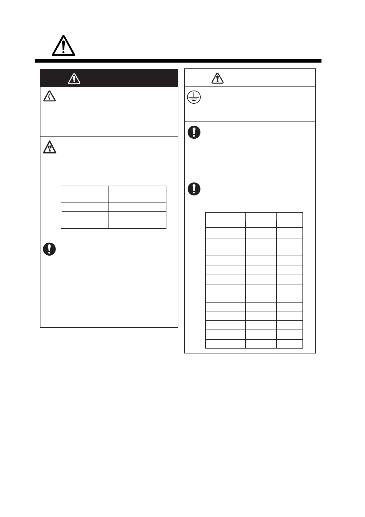
SAFETY INSTRUCTIONS ................................................................................................ i
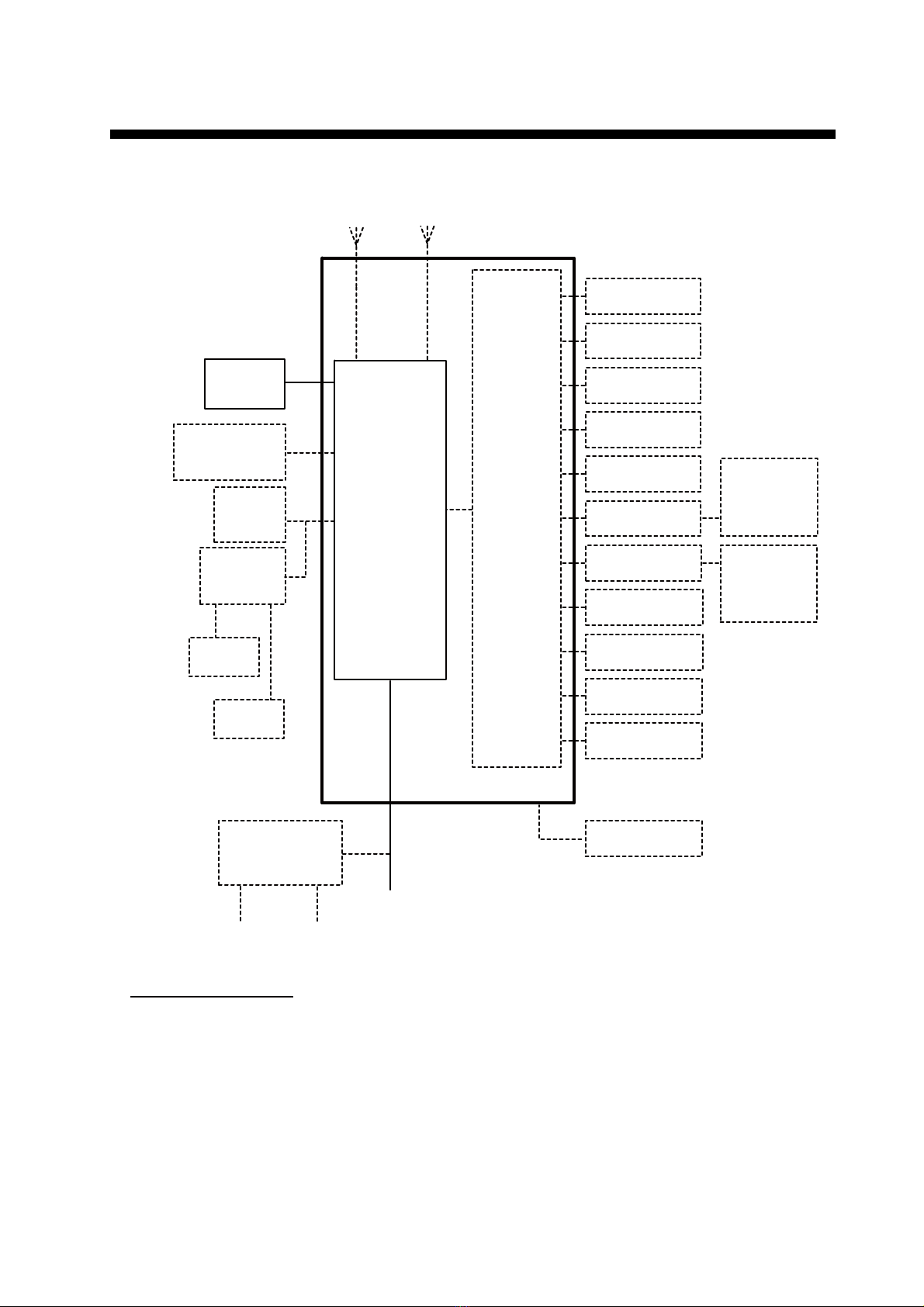
SYSTEM CONFIGURATION ........................................................................................... ii
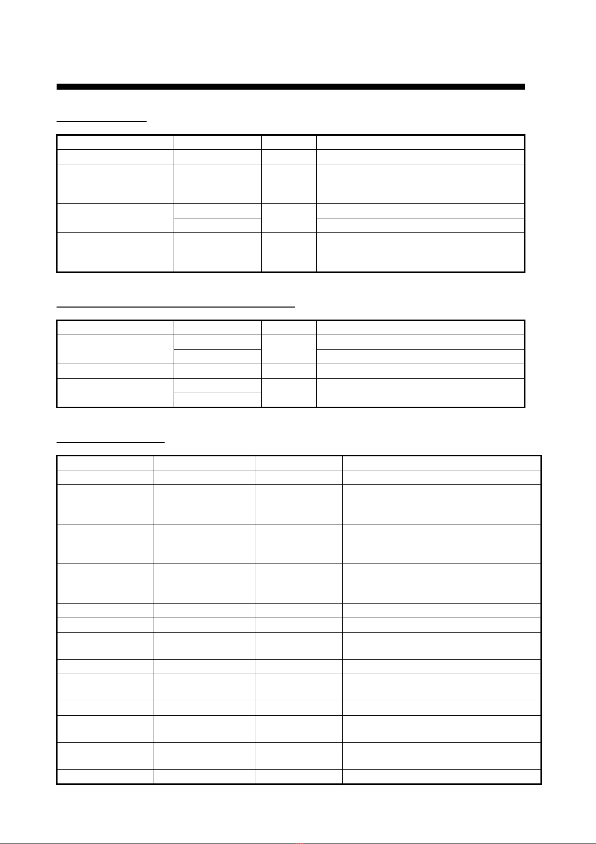
EQUIPMENT LISTS........................................................................................................ iii
1. HOW TO INSTALL THE EQUIPMENT....................................................................... 1
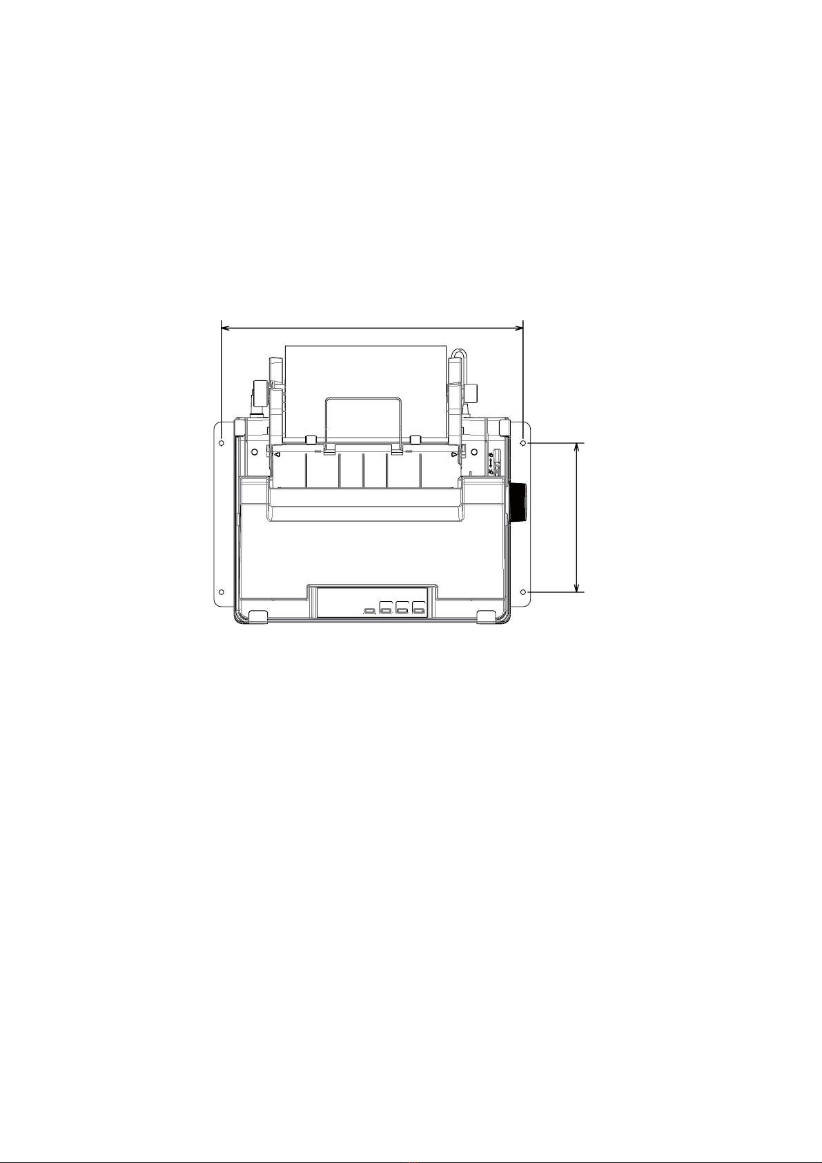
1.1 Transceiver Unit FM-8900S .................................................................................................. 1
1.2 VHF Antenna ........................................................................................................................2
1.3 CH70 RX Antenna ................................................................................................................3
1.4 Handset Hanger....................................................................................................................3
1.5 AC-DC Power Supply Unit PR-240.......................................................................................3
1.6 Printer ...................................................................................................................................4
1.7 Printer Interface IF-8500 .......................................................................................................4
1.8 Loudspeaker SEM-21Q ........................................................................................................4
1.9 Junction Box IF-8900 ............................................................................................................5
1.10 Remote Station RB-8900, Watertight Remote Station RB-8900-W ......................................6
1.11 VHF Console RC-8900 .........................................................................................................7
2. CONNECTIONS.......................................................................................................... 8
2.1 Power Supply........................................................................................................................8
2.2 VHF Antenna ........................................................................................................................9
2.3 CH70 RX Antenna ................................................................................................................9
2.4 Handset HS-2003 .................................................................................................................9
2.5 How to Ground the Transceiver Unit.....................................................................................9
2.6 Junction Box .......................................................................................................................10
2.7 How to Connect the Remote Station without the Junction Box...........................................12
2.8 AC/DC Power Supply Unit PR-240 .....................................................................................13
2.9 When the Handset HS-2003 is not Connected to the Transceiver Unit..............................14
2.10 Rainproof Cover for Transceiver Unit .................................................................................14
2.11 Jumper Setting for Termination...........................................................................................15
2.12 VHF Console.......................................................................................................................16
2.13 I/O Data...............................................................................................................................17
3. HOW TO ASSEMBLE THE VHF CONSOLE KIT .................................................... 18
4. INITIAL SETTINGS................................................................................................... 21
4.1 How to Register the MMSI and ATIS ID .............................................................................21
4.2 Service Menu ......................................................................................................................22
4.3 Settings Inside the Transceiver Unit ...................................................................................25
APPENDIX 1 JIS CABLE GUIDE .............................................................................AP-1
PACKING LISTS ......................................................................................................... A-1
OUTLINE DRAWINGS ................................................................................................ D-1
INTERCONNECTION DIAGRAMS.............................................................................. S-1

The paper used in this manual
is elemental chlorine free.
・FURUNO Authorized Distributor/Dealer
9 52 Ashihara cho,
Nishinomiya, 662 8580, JAPAN
A
:
APR
2012
.
Printed in Japan
All rights reserved.
D
:
AUG
.
26, 2013
Pub. No.
IME-56800-D
(
GREG
)
FM-8900S
0 0 0 1 7 6 2 0 3 1 3

i
SAFETY INSTRUCTIONS
WARNING CAUTION
(MPE: Minimum Permissible Exposure)
100 W/m
2
0.12 m
10 W/m
2
0.39 m
2 W/m
2
0.89 m
IEC 60945
IEC 60945
MPE by FCC
HAZARDOUS VOLTAGE.
Can shock, burn or cause serious
injury.
Do not work inside the equipment unless
totally familiar with electrical circuits.
Do not approach the antenna closer
than the distances shown below when
the antenna is transmitting.
The antenna emits radio waves that can
be harmful to the human body.
Turn off the power at the mains switch-
board before beginning the install-
ation.
Post a warning sign near the switch-
board to indicate that power should
not be applied while the equipment is
being installed.
Electrical shock, serious injury or fire can
result if the power is not turned off or is
applied while the equipment is being
installed.
Ground the transceiver unit.
Ground the transceiver unit to prevent
electrical shock and interference.
Confirm that the power supply
voltage is compatible with the
voltage rating of the equipment.
Connection to the wrong power supply
can cause fire or damage the
equipment.
Follow the compass safe distances
to prevent interference to a magnetic
compass.
RF power density
on antenna aperture
Distance Description
required by
Standard
compass Steering
compass
FM-8900S0.50m 0.30m
IF-8900 2.05m1.35m
HS-20031.50m0.95m
HS-8900 0.45m 0.30m
HS-8900-W0.45m 0.30m
HG-8900 1.75m 1.20m
HG-8900-W1.70m 1.10m
RB-8900 1.40m 0.90m
RB-8900-W1.40m 0.90m
PR-2400.90m0.60m
IF-85001.05m0.70m
SEM-21Q2.20m 1.50m
RC-89002.20m 1.40m

ii
SYSTEM CONFIGURATION
JUNCTION
BOX
IF-8900
TRX
ANT
CH70 RX
ANT
TRANSCEIVER
UNIT*
FM-8900S
24 VDC
AC/DC POWER
SUPPLY UNIT
PR-240
24 VDC
Battery
100-115/200-230 VAC
1ø, 50/60 Hz
HANDSET
HS-2003
EXTERNAL
LOUDSPEAKER
SEM-21Q
PRINTER
PP-520/
PP-8800A
PRINTER
INTERFACE
IF-8500
OTHER
RADIO
NAV
EQUIPMENT
VDR
ALARM
SYSTEM
ALARM UNIT
IC-350
INS/AIS/AMS
PLOTTER
MIC RECEPTACLE
BOX RBD-VHF (B)
MIC RECEPTACLE
BOX RBD-VHF (B)
REMOTE STATION
RB-8900/RB-8900-W
REMOTE STATION
RB-8900/RB-8900-W
REMOTE STATION
RB-8900/RB-8900-W
REMOTE STATION
RB-8900/RB-8900-W
ANALOG WING
HANDSET
HS-6000FZ5/
HS-6000FZ11
ANALOG WING
HANDSET
HS-6000FZ5/
HS-6000FZ11
Environmental category
Antenna units: Exposed to the weather
All other units: Protected from the weather
PRINTER
PP-520
JUNCTION BOX
IF-8900
VHF CONSOLE* RC-8900
* Transceiver unit or VHF
console installed.

iii
EQUIPMENT LISTS
Standard supply
Standard supply (for VHF console RC-8900)
Optional equipment
Name Type Qty Remarks
Transceiver Unit FM-8900S 1 Select one
Installation Materials CP05-12600 1 set For transceiver unit
w/inst. mat. CP05-12601,
cable assy. LP-02-1(7A)-L3000
Accessories FP05-05730 1 set For HS-2003-15
FP05-05720 For HS-2003-15-L
Spare Parts SP05-06201 1 set For transceiver unit
Fuse (Type: FGBO 125V 7A PDF,
Code No.: 000-155-831-10)
Name Type Qty Remarks
VHF Console RC-8900-N 1 No printer
RC-8900-A With printer
Installation Materials CP05-13101 1 set For VHF console
Accessories FP05-05740 1 set For HS-2003-20-L
FP05-05750
Name Type Code no. Remarks
Junction Box IF-8900 - w/Inst. mat. CP05-12701
Remote Station RB-8900-15 - Remote handset HS-8900-15,
Handset hanger HG-8900,
w/Inst. mat. CP05-12801
Remote Station RB-8900-20 - Remote handset HS-8900-20,
Handset hanger HG-8900,
w/Inst. mat. CP05-12801
Watertight
Remote Station
RB-8900-W-15 - Waterproof handset HS-8900-W-15,
Waterproof handset hanger HG-8900-W,
w/Inst. mat. CP05-12801
Remote Handset HS-8900-15 000-020-890
Remote Handset HS-8900-20 000-020-891
Watertight
Remote Handset
HS-8900-W-15 000-020-924
Handset Hanger HG-8900 000-020-892
Watertight
Handset Hanger
HG-8900-W 000-020-925
Flush Mount Kit OP05-129 000-020-883
Hanger Kit OP05-132 000-020-884 Hanger for transceiver unit,
w/accessories
Waterproof Seal OP05-133 001-174-890 For Junction Box IF-8900, to comply with
waterproofing std.
Rainproof Cover OP05-134 001-178-740 For transceiver unit

EQUIPMENT LISTS
iv
External Loud-
speaker
SEM-21Q 001-165-970-10
Dynamic Mic. Set OP05-57 000-045-775 Receptacle Box: RBD-VHF(B)-75BG
Hanger: AP-102
Handset: HS-6000FZ5 (dynamic
mic., curled cable)
Handset Set OP05-42 000-045-778 Receptacle Box: RBD-VHF(B)-75BG
Hanger: AP-102
Handset: HS-6000FZ11 (dynamic
mic., straight cable)
MIC Receptacle
Box
RBD-VHF(B)-75BG 000-056-094
Handset Hanger AP-102 001-081-320-10
Handset HS-6000FZ11 000-135-072-10
Handset HS-6000FZ5 000-112-623-10
Recording Paper TP058-30CL 001-097-110 08S0378 W: 57 mm, L: 30 m
Printer PP-520 -
Ribbon Cartridge 7Q1VP80SF 001-198-190-10
Printer Interface IF-8500 000-053-895
Handset HS-2003-15 000-021-369 w/1.5 m cable, straight connector
Handset HS-2003-15-L 000-021-367 w/1.5 m cable, elbow connector
Handset HS-2003-20-L 000-021-368 w/2 m cable, elbow connector
Handset HS-2003-20 000-054-390 w/ 2m cable
Handset HS-2003-50S 000-054-391 w/5 m straight cable
Handset Hanger FP05-05510 005-951-790 For HS-2003
AC/DC Power
Supply
PR-240 -
Antenna FAB-151D 001-144-490-10
Antenna Fixture 4-310071 000-166-333-10
Connector AP05-01001 005-389-790
Antenna Installa-
tion Materials
CP05-11001 001-034-670
Printer PP-8800A - w/power cable
Emergency Lamp NLFL-03W-WB 000-176-706-10 For rack console
Cable Assy PG05-0053-1 000-158-681-11 Extension cable for HS-2003
Coaxial Cable RG-10/U-Y *10M* 000-159-411-10
Coaxial Cable RG-10/U-Y *20M* 000-159-412-10
Coaxial Cable RG-10/U-Y *30M* 000-159-413-10
Coaxial Cable RG-10/U-Y *40M* 000-159-414-10
Coaxial Cable RG-10/U-Y *50M* 000-159-415-10
Console Kit RC-8900-A-T - Console: RC-8900-A-T
Inst. Mat.: CP05-13201
Accessories:
FP05-06801 (No printer)
FP05-06800 (With printer)
Name Type Code no. Remarks

1
1. HOW TO INSTALL THE
EQUIPMENT
This chapter shows you how to install the units of the system. The transceiver unit and
handset are standard supply. All other units are optional supply. (The junction box is
standard supply in some installations.)
1.1 Transceiver Unit FM-8900S
1.1.1 General installation remarks
The transceiver unit can be installed on a desktop (with hanger), under a desktop,
overhead, bulkhead, or in a console (requires a flush mount kit). Select a location
where the controls can be easily operated and a location that is near the power source
and the ground location. Additionally, select a location that meets the following condi-
tions:
1.1.2 Desktop, bulkhead, overhead installation
1. Use the hanger as a template to mark the fixing holes in the installation location.
2. Fix the hanger to the location with the self-tapping screws and washers (supplied).
(For the overhead mount, use nuts, bolts and washers instead of the self-
tapping screws.)
3. Screw the knob bolts with the washers into the transceiver unit.
4. Set the transceiver unit to the hanger and tighten the knob bolts.
• Select a location away from water spray and water splash.
• The location must not be in direct sunlight, because of heat that can increase inside the unit.
• Leave some additional length in cables to allow a service technician to move the radio from its nor-
mal location with the cables connected.
• Do not install the unit where flammable gases are stored.
• Select a location that provides good ventilation.
• Make sure the location can hold the weight of the unit under the condition of continued vibration
normally found on the ship. If necessary, strengthen the location. For added support use nuts, bolts
and washers (instead of self-tapping screws) to fasten the unit.
• Leave enough space at the sides and rear of the unit for maintenance and service purposes and
to provide cool air. See the outline drawings at the back of this manual for recommended service
space.
• For Solas Convention vessels, the mounting location must satisfy the conditions of Regulations 22
Navigation bridge visibility.
• For installation in a console, select a location where the display can be easily seen.
• The transceiver unit causes interference to a magnetic compass if put too close to the compass.
Follow the compass safe distance in the safety instructions to prevent interference to a magnetic
compass.

1. HOW TO INSTALL THE EQUIPMENT
2
1.1.3 Console installation (flush mount, option)
Requires the optional flush mount kit (OP05-129), the contents of which are shown in
the table below. Follow the instructions in the outline drawing to install the unit in a con-
sole.
1.2 VHF Antenna
1.2.1 Requirements for the antenna
Any good quality antenna that meets the requirements shown below can be used.
1.2.2 Installation location
The location and installation of different antennas on a ship is important to ensure ef-
fective communications. Incorrectly installed antennas will degrade performance of
the radio equipment and reduce the range of communications.
Select the location for the antenna considering the following points.
• VHF antennas should be placed in a position which is as elevated and free as pos-
sible, with at least 2 meters horizontal separation from constructions made by con-
ductive materials.
• Ideally there should not be more than one antenna on the same level.
• The location of mandatory VHF antennas should be given priority compared with
mobile telephone antennas. If they are located on the same level, the distance be-
tween them should be at least 5 meters.
Name Type Code no. Qty
Mounting Plate 05-104-2603 100-370-030-10 1
Self-tapping Screw 5×20 000-802-081 4
Hex Screw M8×16 000-882-075 2
• Frequency range: 155 to 164 MHz
• Impedance: 50 ohms
• Polarization: Vertical
• Handling power: 30 W
• Quality: Withstand the marine environment

1. HOW TO INSTALL THE EQUIPMENT
3
1.2.3 Mounting procedure
The basic mounting procedure for the antennas supplied by FURUNO is as follows;
however, consult appropriate outline drawing for details.
1. Fasten the antenna bracket to the stanchion.
2. Set the antenna to the antenna bracket and tighten bolts.
3. Screw the coaxial cable plug into the antenna.
1.3 CH70 RX Antenna
The antenna must be separated from the antennas, masts, and other objects that can
cause interference. Follow the recommended separation distances in section 1.2.2.
The installation procedure is like that for the VHF antenna. See the outline drawing.
1.4 Handset Hanger
Install the handset hanger to the left of the transceiver unit. The location must provide
easy access to the front panel controls while you operate the handset. The length of
the standard handset cable is 50 cm. Put the handset hanger within 50 cm of the unit.
(Longer cables are available.)
1.5 AC-DC Power Supply Unit PR-240
For Solas Convention vessels, both AC and DC power must be supplied to the trans-
ceiver unit, through an AC/DC power supply. When the AC input fails, DC power is
supplied. FURUNO can supply an AC/DC power supply unit, the PR-240. Provide pro-
tective earth. See chapter 2.
1.5.1 Installation location
Select the location that meets the following conditions:
• Select a location that provides good ventilation.
• The location must be clean and dry.
• Make sure the location can hold the weight of the unit under the condition of contin-
ued vibration normally found on the ship.
• The power supply unit will affect the performance of a magnetic compass if put near
the compass. Follow the compass safe distance in the safety instructions to prevent
the interference to a magnetic compass.

1. HOW TO INSTALL THE EQUIPMENT
4
1.6 Printer
1.6.1 Printer PP-520
See the outline drawing for installation instructions.
1. Decide the location for the printer.
2. Set the ink ribbon cartridge and the roll paper to the printer. See the PP-520’s Op-
erator’s Manual for the procedures.
3. Set the fixtures (left/right) to the printer, and fasten them with four self-tapping
screws (φ5x20).
1.6.2 Printer PP-8800A
See the outline drawing at the back of this manual for information. This printer cannot
be connected to the Printer Interface IF-8500.
1. Make a cutout of 208(W)×133(H) mm in the mounting location.
2. Set the printer to the cutout and fasten the printer with four self-tapping screws
(4×16).
1.7 Printer Interface IF-8500
The Printer Interface IF-8500 allows the FM-8900S and other MF/HF radio communi-
cation equipment to share the Printer PP-520. See the outline drawing at the back of
this manual for installation instructions.
1.8 Loudspeaker SEM-21Q
The loudspeaker can be installed on a desktop, the overhead or a bulkhead. Fasten
the loudspeaker with the self-tapping screws, or nuts, bolts and washers. See the out-
line drawing at the back of this manual for dimensions.
405
200

1. HOW TO INSTALL THE EQUIPMENT
5
1.9 Junction Box IF-8900
The junction box can be mounted on a desktop or bulkhead, and is required to connect
the remote station, wing handset, etc. Put the unit within 5 m of the transceiver unit,
because that is the length of the cable connected between the units.
For the bulkhead mount, it is necessary to cover holes in the bottom of the unit to
comply with the Ingress Protection Rating IPx2. Waterproof seals (Type: OP05-133,
Code no.: 001-174-890) are optionally available for this purpose. Set them to the open
holes on the underside of the junction box as shown below, BEFORE installing the
junction box.
To install the junction box, open the cover and fasten the box with four self-tapping
screws (5×20). Close the cover.
Fixing
hole
Fixing
hole
= Hole where to attach
waterproofing seal
CABLE SLOT SIDE
To FM-8900S
Card spacer

1. HOW TO INSTALL THE EQUIPMENT
6
1.10 Remote Station RB-8900, Watertight Remote
Station RB-8900-W
A maximum of four remote stations can be installed.
1. Remove six screws on the handset hanger.
2. Remove upper chassis of the hanger.
3. Fasten the base of the hanger to a bulkhead with two self-tapping screws (4×20).
4. Connect the cables to the remote station then assemble the remote station.
1.10.1 How to install the Watertight Remote Station outdoors
The Watertight Remote Station RB-8900-W (with Watertight Remote Handset HS-
8900-W) can be installed outside if it is contained in a waterproof enclosure. As shown
below, apply the silicone sealant to the hanger to waterproof the hanger.
Be sure to put the RB-8900-W in a waterproof enclosure when the unit is installed out-
side. The waterproofing category of the RB-8900-W is IEC 60529 IP56. However, pro-
tect the unit from the weather (IEC 60945).
Before you close the hanger with the silicone sealant (for waterproofing), do the ter-
mination setting (only for termination device, see section 2.11) and connect the ca-
bles. Do not open the hanger after it has been sealed.
1. Fasten the mounting base with the self-tapping screws. Apply the silicone sealant
to the exposed part of those screws.
2. Attach the cable from the transceiver unit or junction box. Apply the silicone seal-
ant to the cable around the cable entrance.
3. Confirm that the plastic washers are in the screw holes. Fasten the cover of the
handset hanger. Apply the silicone sealant to the junction between the mounting
base and the cover.
2. Apply silicone sealant to
cable entrance.
1. Apply silicone
sealant to
self-tapping screws.
3. Apply silicone
sealant to junction.

1. HOW TO INSTALL THE EQUIPMENT
7
1.11 VHF Console RC-8900
Install the VHF console where you can easily operate the equipment in the console
and do maintenance and service. Meet with shipyard personnel and ship's officer-in-
charge to select the best location. The location must meet the following points:
• Select a location where you can operate controls easily.
• Select a location where shock and vibration are the least possible.
• Select a location away from water splash and rain.
• The temperature and humidity of the location must be both stable and moderate.
How to install the console
1. Ask shipyard personnel to tighten six M5 nuts or six M5 bolts to the fixing holes
(on the bulkhead), referring to the outline drawing at the back of this manual.
2. Unfasten the cover assembly from the console.
3. Set the VHF console to the bolts.
4. Fasten the console with the bolts or nuts and weld nuts to the bulkhead.
5. Fasten the cover assembly to the console.
Note: To connect wires after you have hung the console, see section 2.12.
6. Fasten the handset hanger with two screws.
7. To fasten the optional emergency lamp, connect the cable to the terminal board,
then fasten the lamp to the console. Refer to the interconnection diagram and out-
line drawing.

8
2. CONNECTIONS
Connect external equipment at the rear of the transceiver unit.
2.1 Power Supply
2.1.1 Solas Convention vessels, 100/220 VAC ship’s mains
Solas Convention vessels must supply both AC and DC power to the transceiver unit,
through an AC/DC power supply unit. The AC/DC Power Supply Unit PR-240 is op-
tionally available. When the AC input fails, the DC power is activated.
Connect the reserve source of energy to the DC IN terminal on the PR-240. Connect
the AC ship's mains to the AC IN terminal on the PR-240.
Be sure to ground the unit.
2.1.2 Radio battery
Attach the connector (supplied) to the power cable and connect the cable to the 24
VDC connector at the rear of the transceiver unit. Connect the wire ends to the radio
battery line.
24VDC
Connect power
cable.
SPKR
Connect external
loudspeaker.
PRINTER
Connect Printer
PP-520/PP-8800A.
JUNCTION
Connect Junction Box
IF-8900.
ANT
Connect antenna.
CH70 RX ANT
Connect DSC
antenna.
GND terminal
Connect ground
wire.
SPKR
PRINTER
ANT
CH70 RX ANT 24VDC
JUNCTION
4.7A

2. CONNECTIONS
9
2.2 VHF Antenna
The VHF antenna is connected to the transceiver unit with a 50 ohm coaxial cable,
type RG-10/U-Y. Make sure you leave some additional length in the cable for future
service and maintenance.
Lay the coaxial cable and fasten an M-type plug to the cable (if necessary) as follows.
1. Remove the sheath by 35 mm.
2. Bare 23 mm of the center conductor. Trim the braided shield by 10 mm and tin.
3. Slide the coupling ring on the cable.
4. Screw the plug assembly on the cable.
5. Solder plug assembly to the braided shield through the solder holes. Solder the
contact sleeve to the conductor.
6. Screw the coupling ring into the plug assembly.
7. Screw the plug into the ANT connector at the rear of the transceiver unit.
2.3 CH70 RX Antenna
The CH70 RX antenna is connected to the transceiver unit with a 50 ohm coaxial ca-
ble, type RG-10/U-Y. Attach an M-type plug to the cable (if necessary) as shown
above. Screw the plug into the CH70 RX ANT connector at the rear of the transceiver
unit.
2.4 Handset HS-2003
Connect the handset HS-2003 to the HANDSET connector on the front panel.
2.5 How to Ground the Transceiver Unit
Fasten a ground wire (local supply) between the GND terminal at the rear of the trans-
ceiver unit and ship's hull (or ground bus).
Sheath
Braided shield Insulator
Conductor
Plug assembly Contact sleeve
Solder
here.
Cut
conductor
here.
Solder both
sides of hole.
Coupling ring
35 mm
10 mm 2 mm

2. CONNECTIONS
10
2.6 Junction Box
The junction box connects external equipment to the transceiver unit. The cable that
connects between the junction box and the transceiver unit is pre-connected to the
junction box. WAGO connectors connect the external equipment. A terminal opener is
provided inside the junction box to open terminals on the connectors. See the illustra-
tion below for how to use the opener. Terminal lugs are provided to connect the shield
of the TTYCSLA cables.
2.6.1 How to prepare the cables of external equipment
The cables shown are JIS (Japan Industry Standard) cables. See the Appendix for the
equivalent cables.
Cable MPYC-4 (Alarm system)
TB1
(REMOTE1)
TB3
(REMOTE3)
TB7
(ALARM SYSTEM/
INS/AIS/PLOTTER)
TB5
(ANALOG WING(LEFT)/VDR)
TB8
(ALARM UNIT)
TB6
(ANALOG WING(RIGHT)/
GNSS)
TB4
(REMOTE 4)
TB2
(REMOTE 2)
How to open WAGO
connector
Push
Terminal
opener
Push
Twist
Wire
Procedure
1. Twist core.
2. Insert terminal opener
and push.
3. Insert wire into hole. Be
careful not to pinch
sheath.
4. Release terminal opener.
5. Pull wire to confirm
it is correctly inserted.
Lug for connection
of shield of
TTYCSLA cables
75
mm
100
mm
Vinyl tape
A
ttach to WAGO
connector.
20 30 20
Sheath
Armor
5 - 6 L* 50
L*=Depends on location of connector. See
illustration of junction box on page 9 for length.

2. CONNECTIONS
11
Cable TTYCSLA-1 (NAV equipment)
Cable TTYCSLA-4 (Alarm Unit IC-350, INS, AIS, Plotter, MIC Receptacle Box,
Remote Handset
2.6.2 Dummy plates in cable slots
Dummy plates are inserted at the factory in all but three cable slots. Remove or insert
the dummy plates as necessary. Cover unused cable slots to comply to Ingress Pro-
tection Rating IP2x.
5 - 6 20 30 20
Crimp-on
lug
L*
Cover shield with
shrink tubing.
Vinyl tape
more
than
60
L*=Depends on location of connector. See
illustration of junction box on page 9 for length.
5 - 6 20 30 20
Crimp-on
lug
L*
Cover shield with
shrink tubing.
Vinyl tape
more
than
60
L*=Depends on location of connector. See
illustration of junction box on page 9 for length.
Dummy
plate

2. CONNECTIONS
12
2.6.3 How to fasten the cables to the Junction Box
Connect cables to related connectors. Fasten the cables to the cable posts with two
cable ties.
2.7 How to Connect the Remote Station without the
Junction Box
The remote station (MIC receptacle box, etc.) can be connected directly to the trans-
ceiver unit, using the D-sub connector supplied as installation materials. Attach the
connector to the cable as follows.
Fasten cable to
post with two
cable ties.
Cable clamp
Cable
D-sub connector assy. XM3A-3721,
Connector hood XM2S-3712
Shield tape (metal)
Fold back armor,
and then wind shield
tape along edge of cable.

2. CONNECTIONS
13
2.8 AC/DC Power Supply Unit PR-240
The AC/DC Power Supply Unit PR-240 is shipped ready for connection to 200-230
VAC. For connection to 100 VAC-115 VAC, change the tap connection and terminal
board connection as below. Attach applicable label (supplied in accessories) to the
front panel according to the ship's mains.
Power Tap
connection Terminal board Label
200-230 VAC SEL 230 V (a) in figure below 200-230 VAC, 2.2-1.7 A,
1φ, 50/60 Hz
100-115 VAC SEL 115 V (b) in figure below 100-115 VAC, 3.2-2.6 A,
1φ, 50/60 Hz
Remove screw and cover.
Cover
Black
Heat sink
Tap connection
(Pull out to disconnect.)
1
2
3
4
5
6
7
8
SEL
115 V
SEL
230 V
1
2
3
1
2
3
(a) 200-230 VAC
Coil
Relay
3
1
2
J4
Black
Grey
Grey
Attach applicable label.
FRONT PANEL
(b) 100-115 VAC
Terminal board
FRONT PANEL
AC FAIL: Connect to Alarm system.
Output setting: Normally openSet plug to pins 1 and 2 of J4.
Normally closedSet plug to pins 2 and 3 of J4 (factory setting).
AC Power Switch
(With DC power input, DC power is supplied regardless of switch state.)

2. CONNECTIONS
14
Protective earth
Connect a IV-2sq wire between the ship’s ground and the ground terminal on the PR-
240 to prevent electrical shock.
2.9 When the Handset HS-2003 is not Connected to
the Transceiver Unit
When the Handset HS-2003 is not connected to the transceiver unit; namely, the re-
mote handset is used always, turn on [M-HS HOOK] in the [OTHER] menu. See sec-
tion 4.6.
2.10 Rainproof Cover for Transceiver Unit
The optional rainproof cover kit (Type: 05-104-2601, Code No. 001-174-310-10), con-
sisting of a protective hood and double-sided tape, protects the connectors at the rear
of the transceiver unit from rain and water splash. The cover can be used with both
the desktop and flush mount installation methods.Connect the cables to the transceiv-
er unit then install the cover as shown below.
CAUTION
Attach protective earth securely to
the ship's ground.
The protective earth (grounding) is
required to prevent electrical shock.
GND terminal
Attach hood to
transceiver unit.
Attach double-sided tape.
Other manuals for FM-8900S
7
Table of contents
Other Furuno Cordless Telephone manuals

Furuno
Furuno FS-5070 User manual

Furuno
Furuno RB-500 User manual

Furuno
Furuno FS-1575 Manual

Furuno
Furuno FM-8900S Manual

Furuno
Furuno 9ZWFM8800S User manual

Furuno
Furuno FM-8800D User manual

Furuno
Furuno FM-8800D User manual

Furuno
Furuno FS-2570 Manual

Furuno
Furuno FS-1503 User manual

Furuno
Furuno FM-4800 User manual

Furuno
Furuno FM-8000 User manual

Furuno
Furuno FM-8800D User manual

Furuno
Furuno FM-4800 User manual

Furuno
Furuno FS-1570 User manual

Furuno
Furuno FM-8800D/8800S User manual

Furuno
Furuno FM-8800D User manual

Furuno
Furuno FM-4850 User manual

Furuno
Furuno FM-8 User manual

Furuno
Furuno FS-5070 User manual

Furuno
Furuno FM-8900S User manual