Furuno GF-8801 User manual

www.furuno.com
Multi-GNSS
Disciplined Oscillator
Model
GF-8801, GF-8802,
GF-8803
Hardware Specifications
(Document No. SE19-410-006-00)

GF-8801, GF-8802, GF-8803
Hardware Specifications
SE19-410-006-00
IMPORTANT NOTICE
No part of this manual may be reproduced or transmitted in any form or by any means, electronic or
mechanical, including photocopying and recording, for any purpose without the express written permission of
the publisher, FURUNO ELECTRIC CO., LTD.
FURUNO ELECTRIC CO., LTD. All rights reserved.
Any information of this documentation shall not be disclosed to any third party without permission of the
publisher, FURUNO ELECTRIC CO., LTD.
The following satellite systems are operated and controlled by the authorities of each government.
- GPS (USA)
- GLONASS (Russia)
- Galileo (Europe)
- QZSS (Japan)
- SBAS (USA: WAAS, Europe: EGNOS, Japan: MSAS, India: GAGAN)
Thus FURUNO is not liable for the degradation of the above systems so therefore FURUNO cannot guarantee
specification based on their conditions. By solar flare or coronal mass ejection due to solar surface activity,
depending on the scale, there is a possibility that a decrease in reception sensitivity or deterioration in
precision may be temporarily observed. User is expected to be familiar with the System and make full use of it
with their own responsibility.
Although this product is paying attention to compatibility with the past products, due to the correspondence to
various additions of specifications, some actions may differ unavoidably. Regarding the specifications, the
contents described in this document are set as true, and for items not described in this document, the actual
operations of this product are set as true. For this product, if you need items compatible with past products,
please consult us before mass-producing this product.
We pay through attention about the software of this product. But, if perchance you found a bug or a trouble,
please feel free to contact us directly. We will check it, and if it is a bug, we may send you a new version with a
bug fix. If perchance we found a bug or a trouble, we may send you a new version after we contact you.
When we send you the new version software, we may ask you to update software. Therefore, we strongly
recommended being able to access to serial port of this product from outside of your product to make software
update easy. In addition, we also strongly recommend connecting between serial port of this product and
network to remote access and update software.
In this product, FURUNO can ensure safe performance only the commands and the sentences which are
written in this document or are written in the document for this product. Please do not use the commands of the
others products, otherwise this product may have troubles and FURUNO may not support about the troubles.
FURUNO may inform some internal commands for verification etc. In this case, please use the commands only
for operation test and please do not use them for technical operation.
FURUNO ELECTRIC CO., LTD. reserves the right to make changes to its products and specifications without
notice.

GF-8801, GF-8802, GF-8803
Hardware Specifications
SE19-410-006-00
Revision History
Version
Change contents
Date
0
Initial release
2019.4.18

GF-8801, GF-8802, GF-8803
Hardware Specifications
SE19-410-006-00
Table of Contents
1Outline······················································································································1
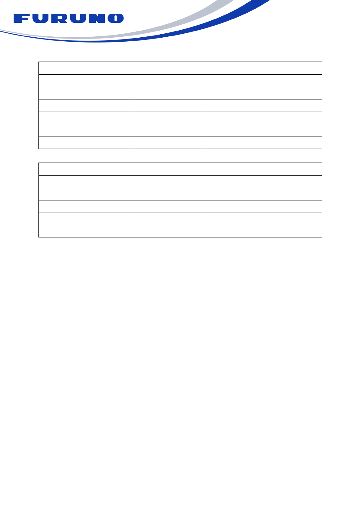
2Function Overview······································································································1
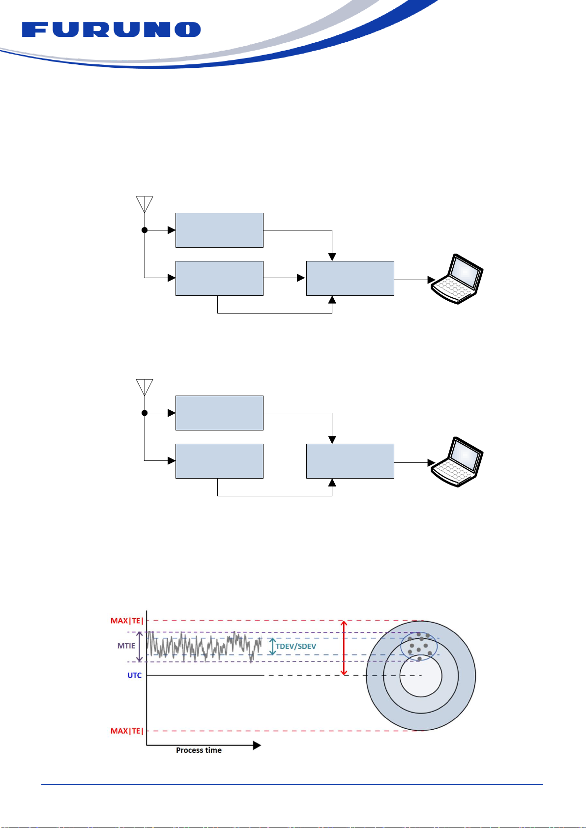
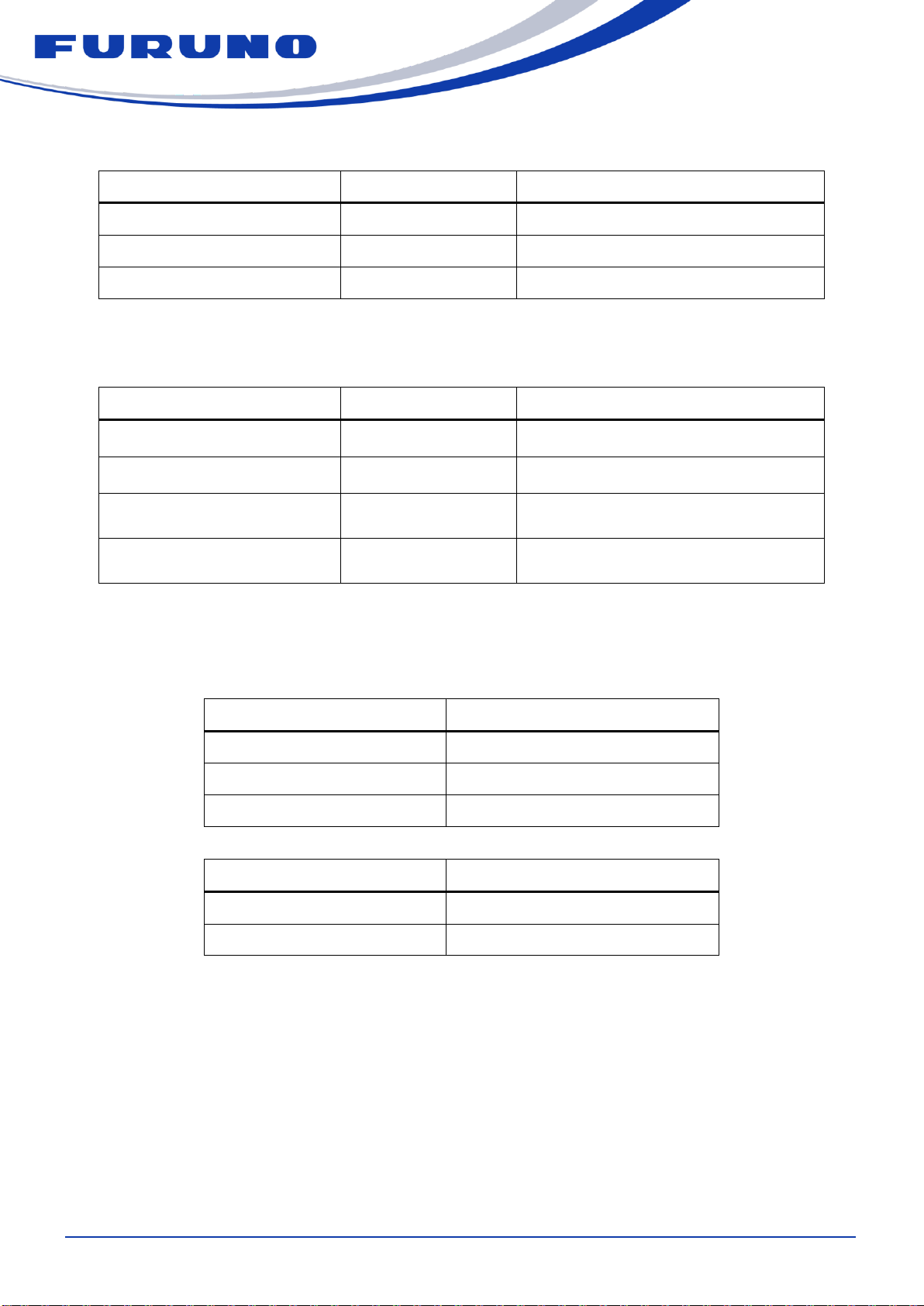
3GNSS General Performance ·························································································2
41PPS and Clock (VCLK, GCLK) Signal Specifications ······················································5
4.1 1PPS··························································································································· 6
4.2 Clock (VCLK)················································································································ 8
4.3 Clock (GCLK) ··············································································································· 9
5Time to FINE LOCK··································································································· 10
6Phase Relation between PPS and VCLK······································································· 10
7Environment Robustness Performance········································································ 11
8Operation Restriction································································································ 11
9I/O Signal Description································································································ 12
9.1 I/O Signal Description ··································································································12
9.2 Pin Arrangement··········································································································13
9.3 Alarm Signal (ALM_N)··································································································13
9.4 Lock Signal (LOCK) ·····································································································13
9.5 PPS Input Signal for External Synchronization (EPPS)·····················································14
9.6 Backup Power Supply (VBK)·························································································14
9.7 RF_COAX and RF_PIN··································································································14
10 Electrical Characteristics··························································································· 15
10.1 Absolute Maximum Rating····························································································15
10.2 Power supply ··············································································································16
10.3 Reset··························································································································17
10.4 Interface Signal ···········································································································17
10.5 Baud Rate and Error ····································································································18
10.6 UART Wake-up Timing ·································································································19
10.7 Recommended GNSS Antenna······················································································20
10.8 Antenna Amplifier Power······························································································20
11 RoHS ······················································································································21
12 Flame Retardancy Rank·····························································································21
13 FIT·························································································································· 21
14 Reliability Test··········································································································21
15 Soldering Condition··································································································21
16 Equivalent Circuit ·····································································································22
17 Mechanical Specifications··························································································22
18 Packaging················································································································24
19 Warranty·················································································································· 25
20 Special Attention ······································································································26
20.1 Precautions for Use ·····································································································26
20.2 Electronic Component··································································································26
20.3 Precautions at Mounting·······························································································26
20.4 Precautions on Industrial Property Rights ······································································27
20.5 Export Control for Security ···························································································27

GF-8801, GF-8802, GF-8803
Hardware Specifications
SE19-410-006-00
1
1 Outline
This document describes the hardware specifications of GF-8801, GF-8802 and GF-8803 which is the GNSS
Disciplined Oscillator (GNSSDO). This document uses GNSS as general term of GPS, GLONASS, Galileo and
QZSS.
2 Function Overview
This product is a GNSSDO that can provide PVT (Position, Velocity and Time) information. Figure 2-1 shows
the block level diagram. Main features are as follows:
Supports GPS, GLONASS, Galileo, QZSS (L1C/A, L1S) and SBAS.
Provides 1PPS with high accuracy and stability synchronized with GPS time or UTC time.
Provides clock signal (VCLK 10MHz) synchronized with 1PPS.
Software upgrade capability by Flash ROM.
Active Anti-Jamming capability to suppress effects of CW jammers.
Effects Multi-path mitigation.
GNSS high sensitivity.
An expensive external power supply component is unnecessary since an LDO is built in.
Coaxial connector (RF_COAX) or IF connector (RF_PIN) for GNSS signal input are selectable.
GF-8701, GF-8702, GF-8703, GF-8801, GF-8802 and GF-8803 are pin compatible.1)
Notes:
1) The specifications of power consumption, PPS and 10 MHz are different.
Multi GNSS
receiver chip
eRideOPUS 7
Serial Flash
ROM
Antenna detection
block with over current
detection function
System power supply block
ITXD
IALM_N
ILOCK
IGCLK
Reset control
block
ESD
Protector
26MHz
TCXO block
10MHz
oscillator block
External
interface
block
VCC_XO
IRXD
IEPPS
VCLK
IRST_N
TXD
ALM_N
LOCK
GCLK
RXD
EPPS
RST_N
VANT
RF_COAX
VCC VBKVANT
3.3V
RF_PIN
Figure 2-1. GF-8801/02/03 block diagram

GF-8801, GF-8802, GF-8803
Hardware Specifications
SE19-410-006-00
2
3 GNSS General Performance
These performances are measured and evaluated under the environment shown in Figure 3-1. The
measurement conditions are default setting and 25°C constant (no wind). When the signal level mask is set,
the performance is limited by the mask.
Multi-GNSS Simulator
GSS6700 RF_COAX
External LNA
Gain: 30.4dB
NF: 0.6dB
Including
Cable Loss
GF-8801
GF-8802
GF-8803
NMEA sentence
TXD
Figure 3-1. Measurement platform
Table 3-1. Time To First Fix (TTFF)
Item
Specification
Note
TTFF (HOT)
< 5 sec
[*1] [*2]
TTFF (COLD)
< 35 sec
[*1] [*3]
Table 3-2. GPS performance
Item
Specification
Note
Signal type
GPS L1C/A
Channel
MAX 12
[*4]
HOT acquisition sensitivity
> -162 dBm
[*5]
COLD acquisition sensitivity
> -148 dBm
[*6]
Tracking sensitivity
> -162 dBm
Re-acquisition sensitivity
> -162 dBm
[*7]

GF-8801, GF-8802, GF-8803
Hardware Specifications
SE19-410-006-00
3
Table 3-3. GLONASS performance
Item
Specification
Note
Signal type
GLONASS L1OF
Channel
MAX 10
[*4]
HOT acquisition sensitivity
> -158 dBm
[*5]
COLD acquisition sensitivity
> -144 dBm
[*6]
Tracking sensitivity
> -158 dBm
Re-acquisition sensitivity
> -158 dBm
[*7]
Table 3-4. Galileo performance
Item
Specification
Note
Signal type
Galileo E1B/E1C
[*8]
Channel
MAX 8
[*4]
HOT acquisition sensitivity
> -136 dBm
[*5]
COLD acquisition sensitivity
> -136 dBm
[*6]
Tracking sensitivity
> -146 dBm
Re-acquisition sensitivity
> -136 dBm
[*7]
Table 3-5. QZSS L1C/A performance
Item
Specification
Note
Signal type
QZSS L1C/A
Channel
MAX 4
[*4] [*11]
HOT acquisition sensitivity
> -136 dBm
[*5]
COLD acquisition sensitivity
> -131 dBm
[*6]
Tracking sensitivity
> -147 dBm
Re-acquisition sensitivity
> -136 dBm
[*7]
GEO satellite
Available
SVID=199 is supported.

GF-8801, GF-8802, GF-8803
Hardware Specifications
SE19-410-006-00
4
Table 3-6. QZSS L1S performance
Item
Specification
Note
Signal type
QZSS L1S
[*9] [*12]
Channel
MAX 2
[*4]
COLD acquisition sensitivity
> -130 dBm
[*6]
Tracking sensitivity
> -134 dBm
Re-acquisition sensitivity
> -130 dBm
[*7]
SLAS
Available
[*10]
Table 3-7. SBAS performance
Item
Specification
Note
Signal type
SBAS L1C/A
SVID=120 to 138 are supported. [*9]
Channel
MAX 2
[*4] [*13]
Acquisition sensitivity
> -130 dBm
[*6]
Tracking sensitivity
> -139 dBm
Reacquisition sensitivity
> -130 dBm
[*7]
[*1] These are specified in the measurement environment shown in Figure 3-1. Simulator output level is set to -130 dBm.
[*2] The time from sending HOT restart command to re-acquisition
[*3] The time from sending COLD restart command to re-acquisition
[*4] Up to 32 channels are available for whole GNSS.
[*5] After sending HOT restart command during satellite receiving
[*6] After sending COLD restart command during satellite receiving
[*7] Within 250 seconds after the last signal receiving
[*8] Due to the composition of the message broadcast by Galileo, TTFF of Galileo may take about 100 seconds.
[*9] Only one of QZSS L1S and SBAS L1C/A can be used. They cannot be received at the same time.
[*10] SLAS correction is performed to GPS and QZSS.
[*11] Up to 4 satellites can be received simultaneously among 193, 194, 195, 196 and 199.
[*12] Up to 2 satellites can be received simultaneously among 183, 184, 185, 186 and 189.
[*13] WAAS, MSAS, EGNOS and GAGAN are supported.

GF-8801, GF-8802, GF-8803
Hardware Specifications
SE19-410-006-00
5
4 1PPS and Clock (VCLK, GCLK) Signal Specifications
The follow is the specifications of 1PPS and clock (GCLK, VCLK). Please refer to the eSIP Protocol
Specification for switching setting etc. The performance described in this chapter is measured and evaluated
under the environment shown in Figure 4-1 and 4-2 below. In the absence of any notes, measurement
conditions are default setting, open sky, constant at 25 degree (no wind).
GF-880X
Evaluation Board
GNSS rooftop
antenna
Universal counter
53132A
Reference GNSS DO
[*1] 1PPS
1PPS
10MHz
CH1
CH2
REF IN
phase
delay
Figure 4-1. 1PPS measurement environment
GF-880X
Evaluation Board
GNSS rooftop
antenna
Universal counter
53132A
Reference GNSS DO
[*1]
VCLK,GCLK
10MHz
10MHz
CH1
REF IN
clock
Figure 4-2. Clock measurement environment
[*1] GNSSDO equipped with rubidium oscillator calibrated by USNO (United States Naval Observatory).
The definition of the terms is as follows.
MAX|TE|: It is a maximum time error (absolute value) of 1PPS for UTC time.
MTIE: Maximum time interval error. It is a relative MIN-MAX value of 1PPS.
SDEV, TDEV: Standard deviation and Time deviation. They show 1PPS fluctuation.

GF-8801, GF-8802, GF-8803
Hardware Specifications
SE19-410-006-00
6
4.1 1PPS
Table 4.1-1. 1PPS general specifications
Item
Specification
Note
Nominal frequency
1 Hz
Duty cycle
50 %
[*1]
Synchronization target
GPS, UTC
[*2]
[*1] The pulse width can be changed by PPS command. Please refer to the eSIP protocol specifications for details.
[*2] 1PPS is output in synchronization with GPS time or UTC time. Please refer to the eSIP protocol specifications for details.
Table 4.1-2. 1PPS output specifications [FINE LOCK]
Item
Specification
Note
1PPS accuracy
(MAX|TE|)
< 40 nsec
MIN-MAX value from UTC time / [*1][*2]
1PPS stability
(Standard deviation)
< 4.5 nsec
@ 1sigma / [*2][*3]
1PPS stability
(Time deviation)
G.8272 PRTC-B
compliant
@ 1sigma / [*2][*4][*6]
1PPS stability
(MTIE)
G.8272 PRTC-B
compliant
Relative MIN-MAX value / [*2][*5][*6]
[*1] It is necessary to adjust cable offset beforehand. In addition, it may be necessary to adjust the hardware offset of the entire
device incorporating this product.
[*2] After SS mode or CSS mode for more than 24 hours, or after TO mode via it
[*3] GF-8701 uses a TCXO as an internal oscillator. Please pay attention to the installation environment since it is particularly
susceptible to wind and temperature.
[*4] TDEV of G.8272 PRTC-B compliant means that it meets the following specifications.
Time deviation limit [nsec]
Observation interval τ [sec]
1
1<τ<100
0.01τ
100<τ<500
5
500<τ<100000
[*5] MTIE of G.8272 PRTC-B compliant means that it meets the following specifications.
MTIE limit [nsec]
Observation interval τ [sec]
0.275τ + 25
1<τ<55
40
55<τ
[*6] G.8272 PRTC-B compliant is GF-8802 and GF-8803 only. TDEV and MTIE of GF-8801 is G.8272 PRTC-A compliant.

GF-8801, GF-8802, GF-8803
Hardware Specifications
SE19-410-006-00
7
Table 4.1-3. 1PPS output specifications [HOLDOVER]
Item
Specification
Note
1PPS
accuracy
(MAX|TE|)
GF-8801
-
GF-8802
< ± 50 usec
@ < 24 hours / [*1][*3]
< ± 3 usec (TYP)
@ < 1 hour / [*2][*3]
GF-8803
< ± 10 usec
@ < 24 hours / [*1][*3]
< ± 3 usec (TYP)
@ < 1 hour / [*2][*3]
1PPS stability
-
Standard deviation / Time deviation / MTIE
[*1] This specification is satisfied when all of the following conditions are satisfied.
The time of power on is more than 7 days before Holdover.
FINE LOCK period (open sky) is more than 72 hours before Holdover.
Temperature variation range is less than ±20°C in the 72 hours just before Holdover and the Holdover period.
Temperature gradient is less than ±5°C/Hour in the 72 hours just before Holdover and the Holdover period.
Temperature integrated value is less than 240 Hour * °C in the 72 hours just before Holdover and the Holdover period.
The temperature integrated value means a time integrated value of temperature variation. It is an integrated value every 24
hours with reference to the temperature at the start of holdover.
Figure 4.1-1 shows the Holdover measurement environment.
5℃/H
24H >72H
Fine Lock
20
40 8H 8H
5℃/H
24H
Temperature
(℃)
Holdover
t
Frequency mode
240H・℃ 240H・℃ 240H・℃
Figure 4.1-1. Holdover measurement environment
[*2] This specification is satisfied when all of the following conditions are satisfied.
The time of power on is more than 1 day before Holdover.
FINE LOCK period (open sky) is more than 10 minutes before Holdover.
Temperature constant (25°C).
Wind does not directly blow.
[*3]
This product learns the frequency variation of the oscillator in FINE LOCK state and reflects the learning result in HOLDOVER
state. Therefore, when the temperature environment is significantly different, the above specifications may not be satisfied. For
example, it is the case when there is no temperature change in FINE LOCK state and there is a temperature change in
HOLDOVER state.
The frequency of the oscillator changes due to fluctuation of gravitational acceleration. Therefore, it is recommended to operate
this product at a fixed point. For moving applications during operation, fluctuations of frequency can be suppressed by not
changing the tilt of the product as much as possible in FINE LOCK state and HOLDOVER state (When the product is operating
horizontally, move it as horizontally as possible). In addition, it is recommended to shorten the travel time as much as possible.
By doing so, it is possible to suppress frequency fluctuations.

GF-8801, GF-8802, GF-8803
Hardware Specifications
SE19-410-006-00
8
4.2 Clock (VCLK)
Table 4.2-1. VCLK general specifications
Item
Specification
Note
Nominal frequency
10 MHz
Short term stability
(Root Allan variance
τ=1sec)
GF-8801
< ± 5E-10
GF-8802
< ± 5E-11
GF-8803
< ± 2E-11
Table 4.2-2. VCLK output specifications [FINE LOCK]
Item
Specification
Note
Long term stability
(24 hours average)
GF-8801
< ± 1E-11
GF-8802
< ± 1E-12
GF-8803
< ± 1E-12
Table 4.2-3. VCLK output specifications [HOLDOVER]
Item
Specification
Note
Long term
stability
(24 hours
average)
GF-8801
-
GF-8802
< ± 1E-9
@ < 24 hours / [*1]
GF-8803
< ± 2E-10
@ < 24 hours / [*1]
[*1] This specification is satisfied when all of the following conditions are satisfied.
The time of power on is more than 7 days before Holdover.
FINE LOCK period (open sky) is more than 72 hours before Holdover.
Temperature variation range is less than ±20°C in the 72 hours just before Holdover and the Holdover period.
Temperature gradient is less than ±5°C/Hour in the 72 hours just before Holdover and the Holdover period.
Temperature integrated value is less than 240 Hour * °C in the 72 hours just before Holdover and the Holdover period.
The temperature integrated value means a time integrated value of temperature variation. It is an integrated value every 24
hours with reference to the temperature at the start of holdover.
The Holdover measurement environment is shown in Figure 4.1-1.

GF-8801, GF-8802, GF-8803
Hardware Specifications
SE19-410-006-00
9
4.3 Clock (GCLK)
Table 4.3-1. Clock (GCLK) output specifications
Item
Specification
Note
GCLK setting range
10 Hz to 40 MHz
[*1]
GCLK stability
< ± 1 ppb
@ 1sigma / [*2]
GCLK output resolution
< ± 8 nsec
clock total jitter / [*3]
Relation between 1PPS and
GCLK
Non coherent
Holdover
No specification
[*1] Please refer to the eSIP Protocol Specifications for GCLK frequency setting.
[*2] It is when the GCLK frequency is 100 Hz or more. When less than 100 Hz, output is possible, but there is no stability
specification.
[*3] It is a mechanism to generate arbitrary frequency by using the system clock of this product and built-in adder. By receiving
the GNSS satellite, it is possible to output arbitrary frequency accurately. Since the frequency is generated using the adder,
it is recommended to check in advance whether jitter and spurious included in the GCLK frequency are within the allowable
range of the application to be used.

GF-8801, GF-8802, GF-8803
Hardware Specifications
SE19-410-006-00
10
5 Time to FINE LOCK
This product transitions to FINE LOCK for GPS time within 5 minutes from power on. However, the conditions
are constant temperature and open sky. Otherwise, the time to FINE LOCK may be extended.
6 Phase Relation between PPS and VCLK
Figure 6-1 shows the phase relation between PPS and VCLK. This relation is coherent.
PPS
VCLK
TPPS(R)_VCLK(R) TPPS(F)_VCLK(R)
Figure 6-1. Phase relation between PPS and VCLK
Table 6-1. Phase relation between PPS and VCLK
Symbol
Description
Min
Max
Note
TPPS(R)_VCLK(R)
VCLK rising delay time from PPS rising
35 nsec
55 nsec
[*1]
TPPS(F)_VCLK(R)
VCLK rising delay time from PPS falling
35 nsec
55 nsec
[*1]
[*1] The frequency mode is PULL-IN, COARSE LOCK or FINE LOCK.

GF-8801, GF-8802, GF-8803
Hardware Specifications
SE19-410-006-00
11
7 Environment Robustness Performance
Table 7-1. Environment robustness performance
Item
Specification
Note
Active anti-jamming
8 CW
[*1]
Multipath mitigation
Available
T-RAIM function
Available
[*2]
Antenna current detection
Available
Spoofing signal mitigation
Available
Anti-spoofing / [*3]
Operating temperature
-40 to +85 °C
[*4]
Storage temperature
-40 to +85 °C
Operation humidity
< 85 %R.H
[*5]
[*1] It has eight anti-jamming functions for CW waves.
[*2] Time Receiver Autonomous Integrity Monitoring (T-RAIM) is a mechanism to identify and eliminate satellites that may have a
bad influence on the positioning calculation by combining and principle of majority when the number of satellites in use is
larger than the minimum number of satellites required for positioning.
[*3] This product has a function to notify an alarm by detecting a spoofing signal, and to eliminate the decoding of spoofing signal.
Please refer to the eSIP Protocol Specifications for details.
[*4] A sudden temperature change may disturb the frequency of the TCXO installed inside, possibly causing instantaneous
satellite reception failure. Especially when installing a fan, it is recommended to take care not to blow the wind directly to
this product.
[*5] Ta=60°C, No condensation
8 Operation Restriction
Operation of this product is limited to the following conditions based on the Wassenaar Arrangement (The
Wassenaar Arrangement on Export Controls for Conventional Arms and Dual-Use Goods and Technologies).
Table 8-1. Operation restriction
Item
Specification
Note
Altitude
< 18300 meters
Velocity
< 515 m/s

GF-8801, GF-8802, GF-8803
Hardware Specifications
SE19-410-006-00
12
9 I/O Signal Description
9.1 I/O Signal Description
Table 9.1-1. I/O signal description
#
Pin name
Type
PU/PD [*1]
Note
1
RST_N
Digital input
PU
External reset input pin [*2]
2
VANT
Power input
-
Power supply input pin for antenna
3
-
-
-
-
4
-
-
-
-
5
GND
-
-
Ground
6
RF_PIN
-
-
GNSS signal input pin [*3]
7
GND
-
-
Ground
8
VBK
Power input
-
Backup power supply input pin [*4]
9
VCC
Power input
-
Main power supply input pin
10
GND
-
-
Ground
11
VCLK
Digital output
-
VCLK output pin (10MHz, Square wave)
12
RXD
Digital input
PU
Serial communication input pin
13
TXD
Digital output
-
Serial communication output pin
14
ALM_N
Digital output
-
Alarm signal output pin [*5]
15
LOCK
Digital output
-
Lock signal output pin [*6]
16
GCLK
Digital output
-
GCLK output pin (10Hz to 40MHz)
17
PPS
Digital output
-
PPS output pin
18
EPPS
Digital input
PD
External PPS input pin
RF
RF_COAX
Analog input
-
GNSS signal input connector [*7]
[*1] PU: Pull-Up, PD: Pull-Down.
[*2] Logic L: Reset, Logic H or open: Normal operation
[*3] VANT voltage is superimposed and output. In case of not using, do not connect anything.
[*4] See Chapter Section 9.6 for the specifications of backup power supply. In case of not using, do not connect anything.
[*5] Logic L: Abnormal, Logic H: Normal. See Section 9.3 for the alarm output condition.
[*6] Logic L: Unlock, Logic H: Lock. See Section 9.4 for the lock signal output condition.
[*7] VANT voltage is superimposed and output. MMCX connector / Receptacle / 50Ω.

GF-8801, GF-8802, GF-8803
Hardware Specifications
SE19-410-006-00
13
9.2 Pin Arrangement
Figure 9.2-1. Top of view
9.3 Alarm Signal (ALM_N)
It shows the status of “alarm” field in CRZ (TPS4) sentence. The alarm signal specification is shown in Table
9.3-1.
Table 9.3-1. Alarm signal specifications
CRZ(TPS4)
“alarm field”
ALM_N pin
Description
00
Logic H
Normal
Other than 00
Logic L
Abnormal
9.4 Lock Signal (LOCK)
It shows the status of “frequency mode” field in CRZ (TPS4) sentence. The output condition can be set by
“Lock port set” field in MODESET command. The lock signal specification is shown in Table 9.4-1.
Table 9.4-1. Lock signal specifications
MODESET
“Lock port set” field
CRZ(TPS4)
“frequency mode”
LOCK pin
0
2, 3, 4
Logic H
Other than above values
Logic L
1 (default)
2, 3
Logic H
Other than above values
Logic L
2
3
Logic H
Other than above value
Logic L
3
3, 4
Logic H
Other than above values
Logic L
#18
#17
#16
#15
#14
#13
#12
#11
#10
#1
#2
#5
#6
#7
#8
#9
#RF⇒

GF-8801, GF-8802, GF-8803
Hardware Specifications
SE19-410-006-00
14
9.5 PPS Input Signal for External Synchronization (EPPS)
When 1PPS is input to the EPPS pin and the command is set up, the VCLK and the PPS will be synchronized
with the pulse. The synchronous target is the rising edge of the pulse to be input to the EPPS. Please refer to
the “EXTSYNC” in the protocol specifications to set the external synchronization function.
9.6 Backup Power Supply (VBK)
When using the backup power supply, the information obtained from the navigation message of each satellite,
the positioning result and the input value of the command set by the user are saved into the backup RAM
(BBRAM) in this product at the main power-off. With this backup function, when this product returns from the
main power-off, the TTFF will be shortened. However, the almanac and the ephemeris data should be received
before the main power shut down. Please refer to the eSIP protocol specifications for the data to be saved into
the BBRAM.
9.7 RF_COAX and RF_PIN
RF_COAX and RF_PIN are GNSS signal input pins. By using the RF_COAX, user can reduce the time for
design and evaluation because of omitting the high frequency circuit design. On the other hand, when using
RF_PIN, user can expect cost reduction since the cable for connecting to RF_COAX is unnecessary.
Only one of RF_COAX and RF_PIN can be used. Use the RF_COAX when the antenna coaxial cable will be
connected directly to the MMCX connector of this product. Use the RF_PIN when GNSS signals are input via
the microstrip line from the user board. Please refer to the Design Guide (SE13-900-000) for the microstrip
line.
RF_COAX and RF_PIN cannot be used at the same time, and it is necessary to switch by the command. The
default is set to the RF_COAX. When the RF_COAX is set, it is not used even if GNSS signals are input to the
RF_PIN.

GF-8801, GF-8802, GF-8803
Hardware Specifications
SE19-410-006-00
15
10 Electrical Characteristics
10.1 Absolute Maximum Rating
Table 10.1-1 shows the values when used in the operating temperature range shown in Chapter 7. Stresses
beyond those listed under those range may cause permanent damage to the product.
Table 10.1-1. Absolute Maximum Rating
Item
Symbol
MIN
MAX
Unit
Note
VCC supply voltage
VCC_ABS
-0.3
6.0
V
Backup supply voltage
VBK_ABS
-0.3
4.0
V
VANT voltage
VANT_ABS
-0.3
6.0
V
Other pins DC voltage
VIN_ABS
-0.5
6.5
V
VOUT_ABS
-0.5
3.8
V
Other pins DC current
-
-
± 50
mA
RF_COAX input power
PRF_COAX_ABS
-
8
dBm
[*1]
-
6
[*2]
-
8
[*3]
RF_IN input power
PRF_IN_ABS
-
-5
dBm
[*1]
-
0
[*2]
-
-1
[*3]
[*1] at 1575.42MHz & 1602MHz
[*2] at 900MHz
[*3] at 1800MHz

GF-8801, GF-8802, GF-8803
Hardware Specifications
SE19-410-006-00
16
10.2 Power supply
Below are power supply specifications. The conditions satisfying this specification are Ta = 25 °C.
Table 10.2-1. Power supply Characteristics
Item
Symbol
MIN
TYP
MAX
Unit
Note
VCC supply voltage
VCC
3.5
3.7
3.9
V
VANT supply voltage
VANT
2.7
-
5.5
V
VBK supply voltage
VBK
1.4
-
3.6
V
Using VBK
VCC rising slew rate
VCC_SR
-
-
3.9x10⁴
V/s
[*1]
VBK rising slew rate
VBK_SR
3.6
-
3.6x10⁴
V/s
[*1]
VCC current
consumption
(at start-up)
GF-8801
ICC_WU01
-
-
150
mA
[*2]
GF-8802
ICC_WU02
-
-
800
[*2]
GF-8803
ICC_WU03
-
-
1400
[*2]
VCC current
consumption
(at stable
state)
GF-8801
ICC_ST01
-
-
150
mA
[*3]
GF-8802
ICC_ST02
-
450
-
[*3]
GF-8803
ICC_ST03
-
600
-
[*3]
VBK current consumption
(at back up)
IBKN
-
9
20
μA
[*4]
VBK current consumption
(at normal operation)
IBKB
-
0.4
2
μA
[*5]
[*1] See Figure 10.2-1 for the rising slew rate.
[*2] Within 5 minutes from power-on.
[*3] After 5 minutes from power-on.
[*4] Vcc = 0 V
[*5] Vcc = 3.7 V
VCC_SR, VBK_SR=⊿V/⊿t
VCC, VBK
⊿V
⊿t
Figure 10.2-1. Rising slew rate
This manual suits for next models
2
Table of contents
Other Furuno Portable Generator manuals
Popular Portable Generator manuals by other brands

Champion Power Equipment
Champion Power Equipment 73534i Owner's manual & operating instructions

Weller
Weller WT 1H Translation of the original instructions

Homelite
Homelite HGCA3000 Series quick start guide

Daihen
Daihen OTC Welbee P402L owner's manual

Firman
Firman P08003 owner's manual

Black Max
Black Max BM907500 Operator's manual

Firman
Firman W03383 owner's manual

Westerbeke
Westerbeke 22.0 KW EDE-60Hz Operator's manual

Broadcast Electronics
Broadcast Electronics RDi 20 RDS product manual

Generac Power Systems
Generac Power Systems Guardian 04077-1 owner's manual

Black Max
Black Max BM907000B Operator's manual

Circutor
Circutor SVG instruction manual