Furuno PR-241 User manual

www.furuno.com
All brand and product names are trademarks, registered trademarks or service marks of their respective holders.
Installation Guide
AC/DC POWER SUPPLY UNIT
Model PR-241
SAFETY INSTRUCTIONS ................................................................................................ i
OVERVIEW...................................................................................................................... 1
EQUIPMENT LIST ........................................................................................................... 1
SYSTEM CONFIGURATION ........................................................................................... 2
1. MOUNTING.................................................................................................................. 2
2. WIRING FOR SINGLE USE ........................................................................................ 3
3. WIRING FOR DUAL USE............................................................................................ 5
4. HOW TO USE THE UNIT ............................................................................................ 9
5. JIS CABLE GUIDE .................................................................................................... 10
SPECIFICATIONS ..................................................................................................... SP-1
OUTLINE DRAWINGS ................................................................................................ D-1
INTERCONNECTION DIAGRAMS.............................................................................. S-1

i
SAFETY INSTRUCTIONS
The operator and installer must read the applicable safety instructions before attempting to install
or operate the equipment.
Observe the following compass safe
distances to prevent deviation of a
magnetic compass:
PR-241
Standard
compass
Steering
compass
0.85 m 0.55 m
CAUTION
CAUTION
WARNING
Mandatory ActionProhibitive ActionWarning, Caution
Indicates a condition that can cause death or serious injury if
not avoided.
Indicates a condition that can cause minor or moderate injury if
not avoided.
WARNING
Turn off the power at the
switchboard before beginning
the installation.
Fire, electrical shock or serious
injurycan result if the power is
left on or is applied while the
equipment is being installed.
Be sure that the power supply is
compatible with the voltage
rating of the equipment.
Connection of an incorrect power
supply can cause fire or damage
the equipment.
Use only the specified power
cable.
Fire or damage to the equipment
can result if a different cable is
used.
Ground the equipment to prevent
electrical shock and mutual
interference.
Do not disassemble or modify the
equipment.
Fire, electrical shock or serious injury
can occur.
WARNING
㆙࿌
To avoid electrical shock, do not
remove cover. No user-serviceable
parts inside.
ឤ㟁䛾ᜍ䜜䛒䜚䚹
䝃䞊䝡䝇䝬䞁௨እ䛾᪉䛿䜹䝞䞊䜢㛤䛡
䛺䛔䛷ୗ䛥䛔䚹ෆ㒊䛻䛿㧗㟁ᅽ㒊ศ䛜
ᩘከ䛟䛒䜚䚸୍䛥䜟䜛䛸༴㝤䛷䛩䚹
Warning Labels(s)
Warning label(s) is(are) attached to the unit.
Do not remove the label(s). If a label is missing
or damaged, contact a FURUNO agent or
dealer about replacement.
Name: Warning Label 1
Type: 86-003-1011-3
Code No.:100-236-233-10

1
OVERVIEW
The PR-241 is a unit integrates the functions of our AC/DC power supply units and rectifiers
listed below.
• AC/DC power supply unit PR-240, PR-300
• Rectifier unit RU-1746B-2, RU-3423, and RU-3424.
Important notices
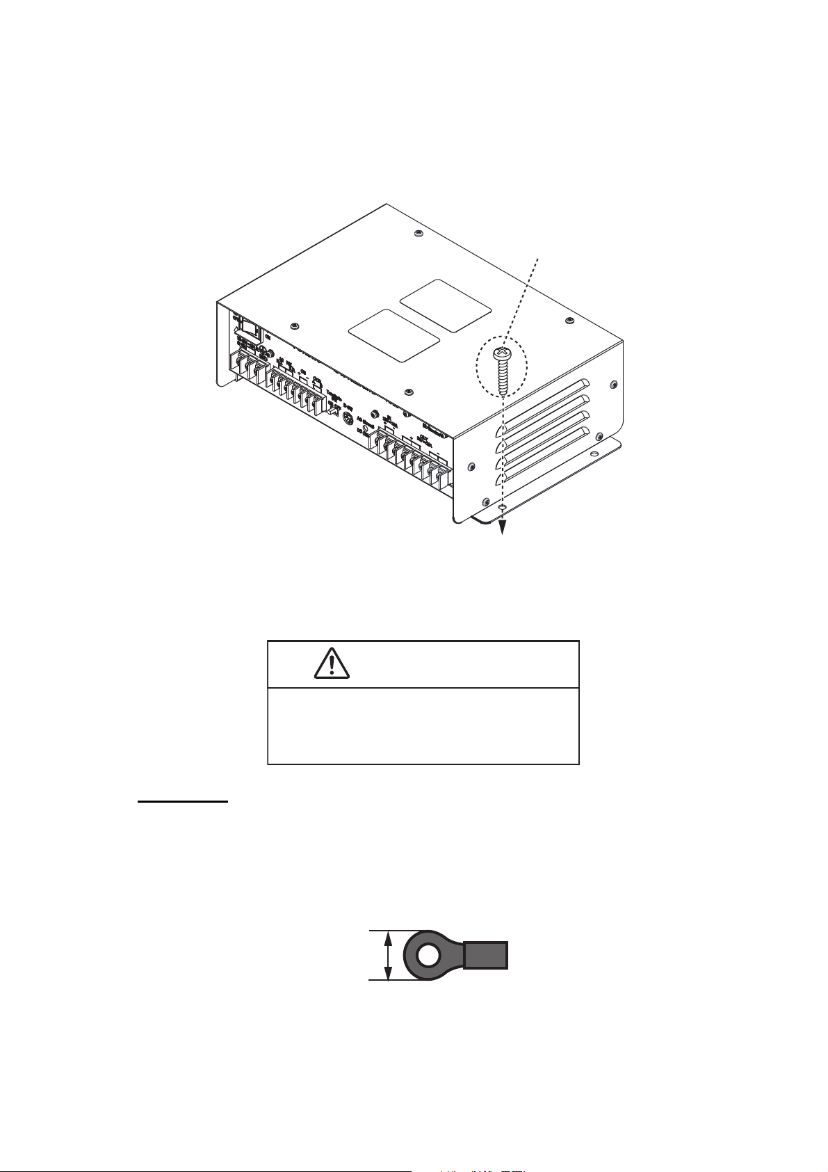
The specifications of PR-241 have been changed to be compatible with DC bypass. The DC
compatible unit has a white dot as shown in the figure below. Up to two units can be con-
nected in parallel, the same as the previous specifications. However, the DC bypass com-
patible units cannot be connected in parallel with the DC bypass non-compatible units.
The differences from the conventional PR-241 (DC bypass non-compatible units) are as
shown in the table below.
The following concern acts as our importer in Europe, as defined in DECISION No 768/
2008/EC.
- Name: FURUNO EUROPE B.V.
- Address: Ridderhaven 19B, 2984 BT Ridderkerk, The Netherland
The following concern acts as our importer in UK, as defined in SI 2016/1025 as amended
SI 2019/470.
-Name: FURUNO (UK) LTD.
-Address: West Building Penner Road Havant Hampshire PO9 1QY, U.K .
Discard this product according to local regulations for the disposal of industrial waste. For
disposal in the USA, see the homepage of the Electronics Industries Alliance (http://www.ei-
ae.org/) for the correct method of disposal.
EQUIPMENT LIST
DC bypass
non-compatible units
DC bypass
compatible units
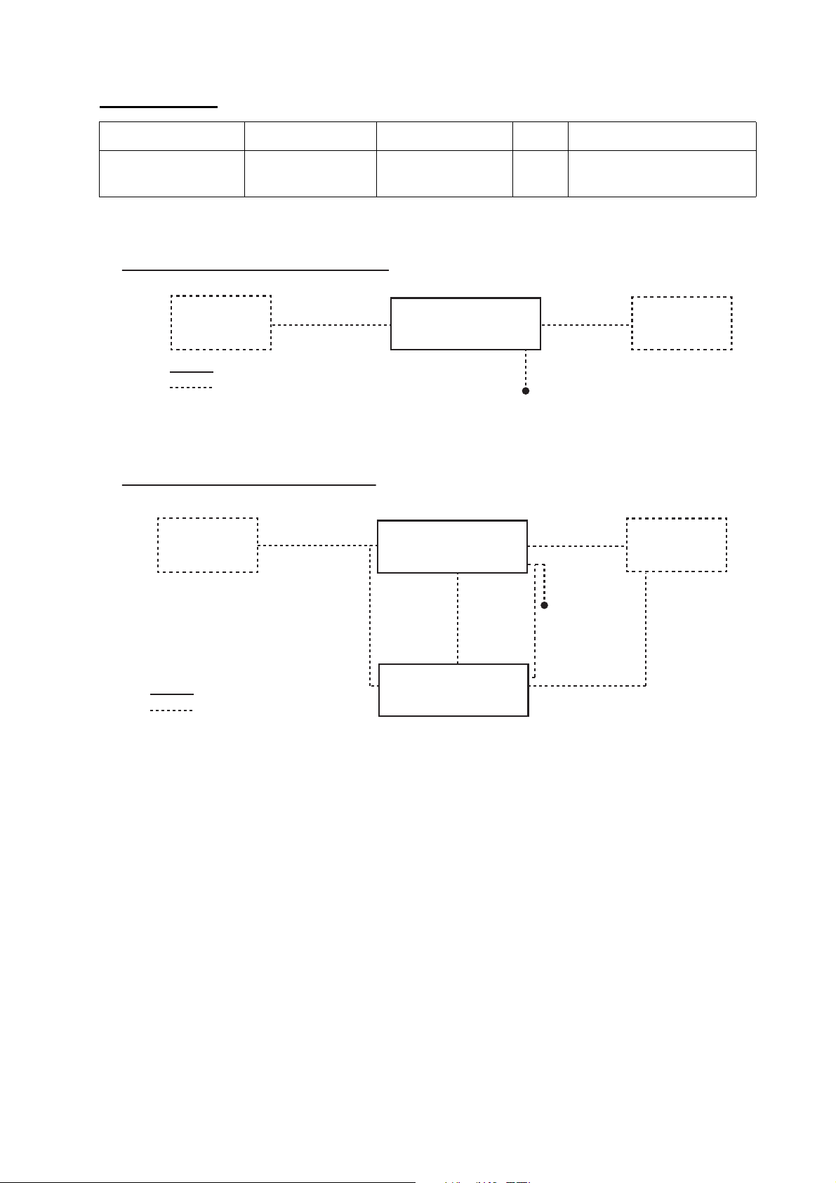
When the input from the AC
power source is disconnected.
No power is supplied from DC
power source.
Power is automatically supplied
from DC power source.
When DC power is turned ON
while the power switch is
turned OFF.
24 VDC is not output. 24 VDC is output.
Standby power when no device
is connected.
Not generated. 4.8 W is generated.
Standard Supply
Name Type Code No. Qty. Remarks
AC/DC Power
Supply unit
PR-241 - 1
DC bypass compatible unit
DC bypass non-compatible unit
Has a
white dot.

2
SYSTEM CONFIGURATION
1. MOUNTING
This unit can be mounted on a desktop or bulkhead. Refer to outline drawing in the back of
this manual when you mount the unit.
When mounting the unit, pay attention to the following points.
• This unit has the following ingress-proof ratings: IP22 for desktop mounting, IP20
for wall mounting.
• When using in dual, do not input from multiple AC power supplies or batteries. Due
to the difference in the load characteristics of the battery and the PR-241, it may not
function as a power supply.
• When using in dual, do not stack the units. Always leave sufficient space between
the units to allow for air-flow and prevent heat build-up. See the outline drawing at
the back of this manual for minimum distances required.
• Turn off the power at the switchboard before beginning the installation.
• Referring to the outline drawings at the back of this manual, leave sufficient room
for service and maintenance.
Optional Supply
Name Type Code No. Qty. Remarks
Ferrite Core OP86-11 001-594-450 1 EMI Cores (GRFC-10, 7
pcs. and GRFC-13, 3 pcs)
AC/DC Power Supply
Unit
PR-241
Backup
Battery
㻔24 VDC㻕
DPYC-2.5 DPYC-2.5
100-230 VAC
TPYC-1.5
DPYC-2.5
DPYC-2.5
TPYC-1.5TTYCSLA-1
:
Standard supply
:
Optional or local supply
Backup
Battery
㻔24 VDC㻕
AC/DC Power Supply
Unit
PR-241
Connected
Equipment
(Up to 20 A)
AC/DC Power Supply
Unit
PR-241
:
Standard supply
:
Optional or local supply
System configuration for single use
DPYC-1.5
100-230 VAC
Connected
Equipment
(Up to 10 A)
TPYC-1.5
DPYC-1.5
System configuration for dual use

3
The mounting procedure is as follows:
1. Referring to the outline drawing at the back of this manual, make four pilot holes
for self-tapping screws (4x16, local supply) in the mounting location.
2. Place the unit in a fixed position and align the screw holes.
3. Secure the unit by tightening the self-tapping screws.
2. WIRING FOR SINGLE USE
Fabrication
Use the following crimp-on lugs (local supply) and cables or equivalent (local supply) for
connection with the power supply unit.
• Power cable: TPYC-1.5, DPYC-1.5
• Crimp-on lugs (see below figure): FV2-P4K
Self-tapping
screws (4x16, 4 pcs.)
CAUTION
To prevent noise and interference,
separate the AC IN, DC IN and DC OUT
cables of this unit from connected
equipment's cables.
FV2-P4K (or equivalent)
7.0 mm

4
Fabrication of TPYC-1.5
Fabrication of DPYC-1.5
The procedure of the wiring is as follows;
1. Unfasten the screws on the terminal cover, then remove the cover. The screws
and cover are required, do not discard them.
9
1515
109109
9
109109
Inner sheath
Armor
Pass the heat shrinkable tube (local supply)
onto the drain wire.
Attach the crimp-on lug
(FV2-P4K) to the core.
Vinyl tape
Drain wireDrain wire
1515
9
109109
Inner sheath
Armor
Vinyl tape
Attach the crimp-on lug
(FV2-P4K) to the core.
Terminal CoverScrews

5
2. Unfasten the binding screws on the terminal and attach the fabricated following
cables to the appropriate terminal.
• TPYC-1.5 (Power cable from ship’s main)
• DPYC-1.5 (Power cable from backup battery)
3. Attach the terminal cover to the unit and fasten the screws removed at step 2.
Note: The terminal cover also acts as protection against water damage and must be
installed.
3. WIRING FOR DUAL USE
Fabrication
Use the following crimp-on lugs (local supply) and cables or equivalent (local supply) for
connection with the power supply unit.
• Power cable: TPYC-1.5, DPYC-2.5
• Signal cable: TTYCSLA-1
• Crimp-on lugs (see below figure): FV2-P4K (for power cable), FV1.25-M3(LF) RED
K (for signal cable)
TPYC-1.5
(Cable from Ship’ s main)DPYC-1.5
㻔Cable from Backup battery㻕
Binding screws
CAUTION
To prevent noise and interference,
separate the AC IN, DC IN and DC OUT
cables of this unit from connected
equipment's cables.
FV2-P4K (or equivalent)
7.0 mm
FV1.25-M3(LF) RED K
(or equivalent)
3.7 mm

6
Fabrication of TPYC-1.5
Note: Attach the Ferrite cores as close as possible to the unit.
Fabrication of DPYC-2.5
Note 1: Attach the Ferrite cores as close as possible to the unit
Note 2: For the DC OUT, attach the ferrite cores without wrapping the cable cores.
9
1515
209209
9
209209
Inner sheath
Armor
Drain wireDrain wire
Pass the heat shrinkable tube (local supply)
onto the drain wire. Attach the crimp-on lug
(FV2-P4K) to the core.
Vinyl tape
Attach the ferrite㻌core
(GRFC-10, optional supply) Attach with no
wrapping.
1515
9
209209
Attach the ferrite㻌core
(GRFC-13, optional supply)
122
Inner sheath
Armor
Vinyl tape
Wrap the cable
cores around the
ferrite core twice.
Attach the crimp-on lug
(FV2-P4K ) to the core.

7
Fabrication of TTYCSLA-1
Note: Attach the Ferrite cores as close as possible to the unit.
Installations for dual use, make the necessary connections with the following
procedure.
1. Refer to the step 1 on page 4, unfasten the screws on the terminal cover, then
remove the cover. The screws and cover are required, do not discard them.
2. Refer to the step 2 on page 5, unfasten the binding screws on the terminal and
attach the fabricated following cables to the appropriate terminal.
• TPYC-1.5 (Power cable from ship’s main)
• DPYC-2.5 (Power cable from backup battery)
• TTYCSLA-1 (Signal cable between main and sub)
1515
9
209209
Inner sheath
Armor
Attach the crimp-on lug
(FV1.25-M3(LF) RED K)
to the core.
Vinyl tape
Attach the ferrite㻌core .
(GRFC-10, optional supply)

8
Note 1: To prevent current imbalance, the input and output cables indicated in the be-
low figures must be the same length and the difference in the resistance value of the
cables must be 3 mΩor less.
Note 2: When backing up power from the battery, signal cable connection is not re-
quired.
3. Attach the terminal cover to the unit and fasten the screws removed at step 2.
Note: The terminal cover also acts as protection against water damage and must be
installed.
The maximum length of the cable that connects between
the main and sub is as shown in the table below.
Main Sub
AC
IN DC
IN
DC
IN
DC
OUT
DC
OUT
Current
Share
AC
IN
Communication
Purpose Cable Maximum Length Pattern of Cable
AC IN TPYC-1.5 90 cm
DC IN 90 cm
DC OUT 50 cm
Current Share 70 cm
Communication 20 m
DPYC-2.5
TTYCSLA-1
PR-241
(Main)
Connected
Equipment
PR-241
(Sub)
PR-241
(Main)
PR-241
(Sub)
In the case the connected
equipment is single In the case the connected
equipment is multiple
Terminal (Local supply)
䠖Output from the main
䠖Output from the sub
Same
Length
Same
Length
Same
Length
Same
Length
Connected
Equipment
Connected
Equipment

9
4. HOW TO USE THE UNIT
Use the power switch to turn this unit on.
After turning on the power switch, the LED lights up as follows:
• AC is selected as the input: Green
• Battery is selected as the input: White
• No Input: OFF
Procedure in dual use
Note 1: Do not use the ID SW and Terminate SW of this unit when using this unit in
dual.
Note 2: To avoid breaking the breaker, set the total current to 20A or less before start-
ing the unit up.
The procedure in dual use is as follows:
Note: If you do not follow this procedure, the breaker may break.
1. Turn on the main switch.
2. Turn on the sub switch.
3. Turn on the ship’s main switch.
Maintenance
• If the LED does not turn on when the power switch is turned on, contact your local
dealer.
• If the breaker breaks, check the cause and take corrective action before resetting
the breaker.
• If the breaker is cut off again after doing above, contact your local dealer.
LED
Power Switch Breaker

10
5. JIS CABLE GUIDE
Core
Type Area Diameter
The following reference table lists gives the measurements of JIS cables commonly used with Furuno products:
TTYCSLA-4
MPYC-4
TPYCY
DPYCY
Cable
Diameter
DPYC-1.5 1.5mm
2
1.56mm 11.7mm
DPYC-2.5 2.5mm
2
2.01mm 12.8mm
DPYC-4 4.0mm
2
2.55mm 13.9mm
DPYC-6 6.0mm
2
3.12mm 15.2mm
DPYC-10 10.0mm
2
4.05mm 17.1mm
DPYCY-1.5 1.5mm
2
1.56mm 13.7mm
DPYCY-2.5 2.5mm
2
2.01mm 14.8mm
DPYCY-4 4.0mm
2
2.55mm 15.9mm
MPYC-2 1.0mm
2
1.29mm 10.0mm
MPYC-4 1.0mm
2
1.29mm 11.2mm
MPYC-7 1.0mm
2
1.29mm 13.2mm
MPYC-12 1.0mm
2
1.29mm 16.8mm
TPYC-1.5 1.5mm
2
1.56mm 12.5mm
TPYC-2.5 2.5mm
2
2.01mm 13.5mm
TPYC-4 4.0mm
2
2.55mm 14.7mm
TPYCY-1.5 1.5mm
2
1.56mm 14.5mm
TPYCY-2.5 2.5mm
2
2.01mm 15.5mm
TPYCY-4 4.0mm
2
2.55mm 16.9mm
TTYCSLA-1 0.75mm
2
1.11mm 9.4mm
TTYCSLA-1T 0.75mm
2
1.11mm 10.1mm
TTYCSLA-1Q 0.75mm
2
1.11mm 10.8mm
TTYCSLA-4 0.75mm
2
1.11mm 15.7mm
TTYCY-1 0.75mm
2
1.11mm 11.0mm
TTYCY-1T 0.75mm
2
1.11mm 11.7mm
TTYCY-1Q 0.75mm
2
1.11mm 12.6mm
TTYCY-4 0.75mm
2
1.11mm 17.7mm
TTYCY-4SLA 0.75mm
2
1.11mm 19.5mm
TTYCYSLA-1 0.75mm
2
1.11mm 11.2mm
TTYCYSLA-4 0.75mm
2
1.11mm 17.9mm
TTPYCSLA-1 0.75mm
2
1.11mm 9.2mm
TTPYCSLA-1T 0.75mm
2
1.11mm 9.8mm
TTPYCSLA-1Q 0.75mm
2
1.11mm 10.5mm
TTPYCSLA-4 0.75mm
2
1.11mm 15.3mm
EX: TTYCYSLA - 4 MPYC - 4
Designation type # of twisted pairs Designation type # of cores
1 3 4 5 6 1 2 3 4
Cables listed in the manual are usually shown as Japanese Industrial Standard (JIS). Use the following guide to locate
an equivalent cable locally.
JIS cable names may have up to 6 alphabetical characters, followed by a dash and a numerical value (example:
DPYC-2.5).
For core types D and T, the numerical designation indicates the cross-sectional Area (mm
2
)of the core wire(s) in the
cable.
For core types M and TT, the numerical designation indicates the number of core wires in the cable.
1. Core Type
D:
Double core power line
T:
Triple core power line
M:
Multi core
TT:
Twisted pair communications
(1Q=quad cable)
2. Insulation Type
P:
Ethylene Propylene Rubber
3. Sheath Type
Y:
PVC (Vinyl)
4. Armor Type
C:
Steel
5. Sheath Type
Y:
Anticorrosive vinyl
sheath
6. Shielding Type
SLA:
All cores in one shield, plastic
tape w/aluminum tape
-SLA:
I
ndividually shielded cores,
plastic tape w/aluminum tape
Core
Type Area Diameter
Cable
Diameter

FURUNO
PR-241
SP - 1 E5003S06B
201105
SPECIFICATIONS OF AC/DC POWER SUPPLY UNIT
PR-241
1 GENERAL
1.1 Rated input voltage 100-230 VAC, 1 phase, 50-60 Hz and
24 VDC from backup battery
1.2 Input current under no-load 0.8 A max. (60 Hz), 1.0 A max. (50 Hz)
1.3 Rated output voltage 24 VDC±5%: 10 A max. (up to two units connectable)
1.4 LED indication Input source status (AC: green, DC: white)
1.5 Protective circuit Over current for in/out and over voltage for output
1.6 Switching backup battery Auto switching from relay
1.7 AC failure detection Relay contact: 1 A, 250 VAC
2 ENVIRONMENTAL CONDITIONS
2.1 Ambient temperature -15°C to +55°C (storage: -20°C to +70°C)
2.2 Relative humidity 93% or less at +40°C
2.3 Degree of protection IP22 (tabletop mount), IP20 (bulkhead mount)
2.4 Vibration IEC 60945 Ed.4
3 UNIT COLOR
N2.5

11/Sep/2020 H.MAKI
Hiromasa Maki
電子署名者: Hiromasa Maki
日付: 2020.09.11 11:24:32
+09'00'
D-1

$
%
&
'5$:1
&+(&.('
$33529('
':*1R
7,7/(
1$0(
ྡ⛠
127(
,17(5&211(&7,21',$*5$0
5()1R
6&$/( 0$66
NJ
7<$0$6$.,
6+,3<$5'6833/<
&21
$&B,1+
$&B,1&
*1'
P0$;
73<&
&20B$
&20B%
&6B3
&6B0
$&B)$,/B5(9
$&B)$,/B&20
&21
$&B)$,/
'&B287B3
'&B287B3
'&B287B3
'&B287B0
'&B287B0
'&B287B0
'&B,1B3
'&B,1B0
&21
*)5&
(0,&25(
*)5&
$&'&32:(56833/<81,7
$&'&㟁※ࣘࢽࢵࢺ
77<&6/$
P0$;
P0$;
'3<&
351R
┦⤖⥺ᅗ
35
$&'&㟁※ࣘࢽࢵࢺ
$&'&32:(56833/<81,7
&&$
-DQ
-DQ +0$.,
$&)$,/
9'&
56
(48,30(17
9'&$0$;
9$&
ȭ+]
&21
$&B,1+
$&B,1&
*1'
P0$;
73<&
&20B$
&20B%
&6B3
&6B0
$&B)$,/B5(9
$&B)$,/B&20
&21
$&B)$,/
'&B287B3
'&B287B3
'&B287B3
'&B287B0
'&B287B0
'&B287B0
'&B,1B3
'&B,1B0
&21
*)5&
(0,&25(
*)5&
$&'&32:(56833/<81,7
$&'&㟁※ࣘࢽࢵࢺ
P0$;
'3<&
'3<&
351R
*)5&
'3<&
ὀグ
㸨㸯㸧㐀⯪ᡤᡭ㓄ࠋ
(0,&25(
*)5&
*)5&
(0,&25(
*)5&
㸨㸰㸧(0,ࢥ*)5&ࡣⰺ⥺ࢆᅇ㏻ࡍࡇࠋ
77<&6/$
77<&6/$
%$&.83%877(5<
(0,&25(*)5&6+28/'%(3$66('7+(&25(67:,&(
28/May H.MAKI
S-1

FURUNO
PR-241
SP-1 J5003S06B
201105
AC/DC 電源ユニット PR-241 仕 様
1.総合
(1) 定格入力 AC100-230 V、単相、50-60 Hz および DC24 V(バックアップ電源)
(2) 無負荷時入力電流 0.8 A 以下(60 Hz)、1.0 A 以下(50 Hz)
(3) 定格出力 DC24 V ±5%: 10 A 以下(最大 2 台まで機器接続可)
(4) LED 表示 入力電源の状態表示(AC:緑、DC:白)
(5) 保護機能 入出力過電流保護および出力過電圧保護
(6) DC バックアップ切替 リレーによる自動切替
(7) AC FAIL リレー接点出力 1A、AC250 V
2.環境条件
(1) 使用温度範囲 -15℃~+55℃(保存温度:-20℃~+70℃)
(2) 相対湿度 93%以下(+40℃)
(3) 保護等級 IP22(卓上装備)、IP20(壁掛装備)
(4) 振動 IEC60945 Ed.4
3.ユニットカラー
N2.5

10
2 台で使用する場合の手順
注1)「ID SW」、および「Terminate SW」の各スイッチは使用しないでください。
注 2)本機のブレーカが切れる恐れがあるため、接続されている機器の電流の
合計が 20A 以内であることを確認してください。
本機を 2 台で使用す る 場合の手順は、 以下の通 り です。
注)この手順通りに行わないと、本機のブレーカが切れる恐れがあります。
1. メインの電源スイッチをオンにします。
2. サブの電源スイッチをオンにします。
3. 船内電源のスイッチをオンにします。
保守
・ 電源スイッチをオンにして、LED が点灯しない場合は、お買い上げの販売店・
代理店、最寄りの当社支店・営業所にお問い合わせください。
・ ブレーカが切れた場合は、原因を調査・対応してからブレーカをリセットし
てください。
・ 上記の対応後に、ブレーカが再び切れた場合は、お買い上げの販売店・代理
店、最寄りの当社支店・営業所にお問い合わせください。

9
注 1)電流バランスが崩れるのを防ぐため、本機を 2 台で使用する時は下図の
通り接続機器と本機のメイン、およびサブの間の出力ケーブルの長さを揃
え、ケーブルの抵抗値の差が 3mΩ 以下であることを確認してください。
注 2)バッテリーから電源をバックアップする際は、信号ケーブルの接続は
不要です。
4. 端子台カ バーを本機に取 り 付け、 手順 1 で取 り 外 し たネジ を締め付けます。
注)端子台カバーは端子部の防水用途も兼ねているため、必ず取り付けてくだ
さい。
4. 基本操作
本機を使用するときは、電源スイッチをオンにします(下図参照)。
電源スイッチをオンにすると、本機の LED が以下の通り点灯します。
・ 入力電源として、AC が選択されている場合:緑
・ 入力電源として、バッテリーが選択されている場合 : 白
・ 入力がない場合 : 消灯
㻼㻾㻙㻞㻠㻝
䠄䝯䜲䞁䠅
᥋⥆ᶵჾ
㻼㻾㻙㻞㻠㻝
䠄䝃䝤䠅
㻼㻾㻙㻞㻠㻝
䠄䝯䜲䞁䠅
᥋⥆ᶵჾ
㻼㻾㻙㻞㻠㻝
䠄䝃䝤䠅
᥋⥆ᶵჾ
᥋⥆ᶵჾ䛜༢⊂䛾ሙྜ ᥋⥆ᶵჾ䛜」ᩘ䛾ሙྜ
➃Ꮚྎ 䠄⌧ᆅᡭ㓄䠅
䠖 䝯䜲䞁䛛䜙䛾ฟຊ
䠖 䝃䝤䛛䜙䛾ฟຊ
㛗䛥䜢
ᥞ䛘䜛
㛗䛥䜢
ᥞ䛘䜛
㛗䛥䜢
ᥞ䛘䜛
㛗䛥䜢
ᥞ䛘䜛
㻸㻱㻰
㟁※䝇䜲䝑䝏 䝤䝺䞊䜹䛾䝸䝉䝑䝖䝪䝍䞁㻌

8
本機を 2 台で使用する場合の結線は、以下の手順で行います。
1. 4 ページの手順 1 を参照して、端子台カバーのネジ 2 本を緩め、端子台カ
バーを取り外します。
2. 5 ページの手順 2 を参照して、端子台からバインドセムスネジを緩めて取り
外し、以下のケーブルの結線を行います(下図、および相互結線図参照)。
・ TPYC-1.5(AC 入力)
・ DPYC-2.5(DC 入力)
・ TTYCSLA-1(通信、カレントシェア)
䝯䜲䞁 䝃䝤
䝯䜲䞁䛸䝃䝤䜢᥋⥆䛩䜛䜿䞊䝤䝹䛾✀㢮䚸 䛚䜘䜃᭱㛗䛿ୗ⾲䛾㏻䜚䛷䛩䚹
㻭㻯
ධຊ ㏻ಙ 㻰㻯
ධຊ
㻰㻯
ฟຊ
㻭㻯
ධຊ
㻰㻯
ฟຊ
㻰㻯
ධຊ
㏻ಙ
䜹䝺䞁䝖
䝅䜵䜰
✀㢮 䜿䞊䝤䝹 ᭱㛗 䜿䞊䝤䝹䛾䝟䝍䞊䞁
㻭㻯ධຊ 㼀㻼㼅㻯㻙㻝㻚㻡 㻥㻜䠿䡉
㻰㻯ධຊ 㻥㻜䠿䡉
㻰㻯ฟຊ 㻡㻜䠿䡉
䜹䝺䞁䝖䝅䜵䜰 㻣㻜䠿䡉
㏻ಙ 㻞㻜䡉
㻰㻼㼅㻯㻙㻞㻚㻡
㼀㼀㼅㻯㻿㻸㻭㻙㻝

7
DPYC‐2.5 の端末処理
注 1)フェライトコアは、本体に近い位置で取り付けてください。
注 2)DC 出力の場合は、フェライトコアに芯線を巻く必要はありません。
TTYCSLA-1 の端末処理
注)フェライトコアは、本体に近い位置で取り付けてください。
15mm15mm
䛒䛨䜝䛜䛔
ෆ㒊䝅䞊䝇
䝡䝙䞊䝹䝔䞊䝥
ᅽ╔➃Ꮚ 䠄㻲㼂㻞㻙㻼㻠㻷䠅 䜢
ྲྀ䜚䛡䜛
䠄༢ 䠖 㼙㼙䠅
9
209209
䝣䜵䝷䜲䝖䝁䜰 䠄㻳㻾㻲㻯㻙㻝㻟䚸 䜸䝥䝅䝵䞁䠅
䜢ྲྀ䜚䛡䜛
㻝㻞㻞㼙㼙
䝣䜵䝷䜲䝖䝁䜰䛻䚸
ⰺ⥺䜢 㻞 ᅇᕳ䛟
1515
䛒䛨䜝䛜䛔
ෆ㒊䝅䞊䝇
䝡䝙䞊䝹䝔䞊䝥
ᅽ╔➃Ꮚ 䠄㻲㼂㻝㻚㻞㻡㻙㻹㻟㻔㻸㻲㻕㻌㻾㻱㻰㻌㻷䠅 䜢
ྲྀ䜚䛡䜛
䠄༢ 䠖 㼙㼙䠅
9
209209
䝣䜵䝷䜲䝖䝁䜰 䠄㻳㻾㻲㻯㻙㻝㻜䚸 䜸䝥䝅䝵䞁䠅
䜢ྲྀ䜚䛡䜛䚹
Table of contents