Furuno RC-1800T User manual

www.furuno.com
A
ll brand and product names are trademarks, registered trademarks or service marks of their respective holders.
Installation Manual
GMDSS Radio Station
Model RC-1800T
(FS-1575/FS-2575 installation-in-field specification)
SAFETY INSTRUCTIONS ................................................................................................ i
SYSTEM CONFIGURATION ........................................................................................... ii
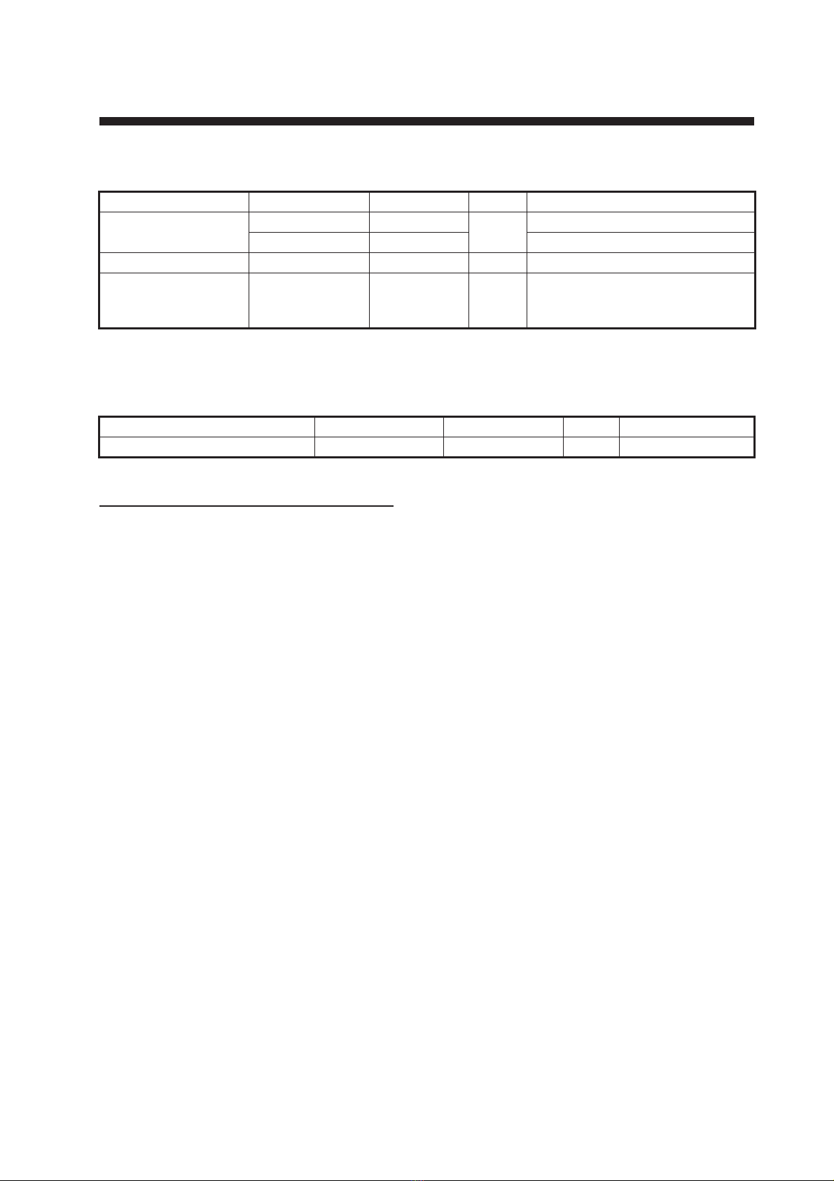
EQUIPMENT LISTS........................................................................................................ iii
1. INSTALLATION.......................................................................................................1-1
1.1 Installation Considerations.................................................................................................1-1
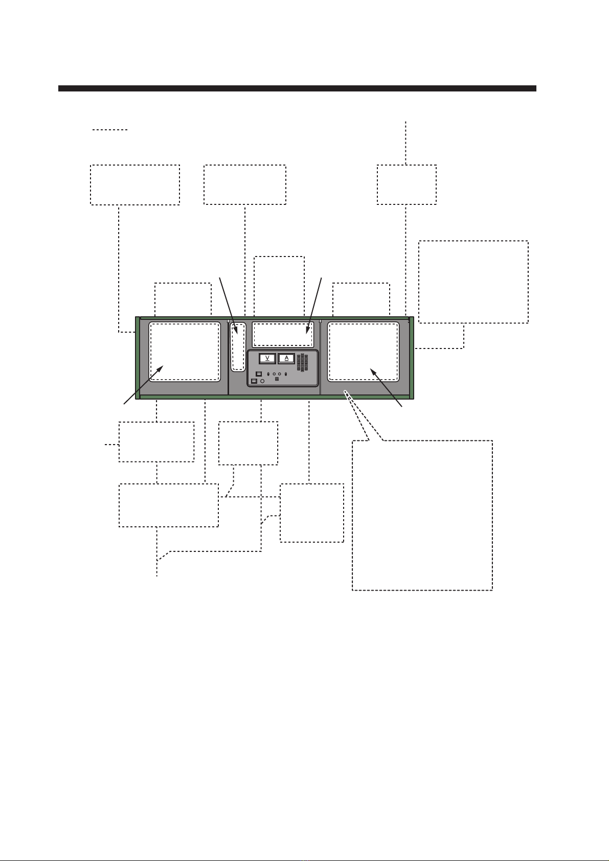
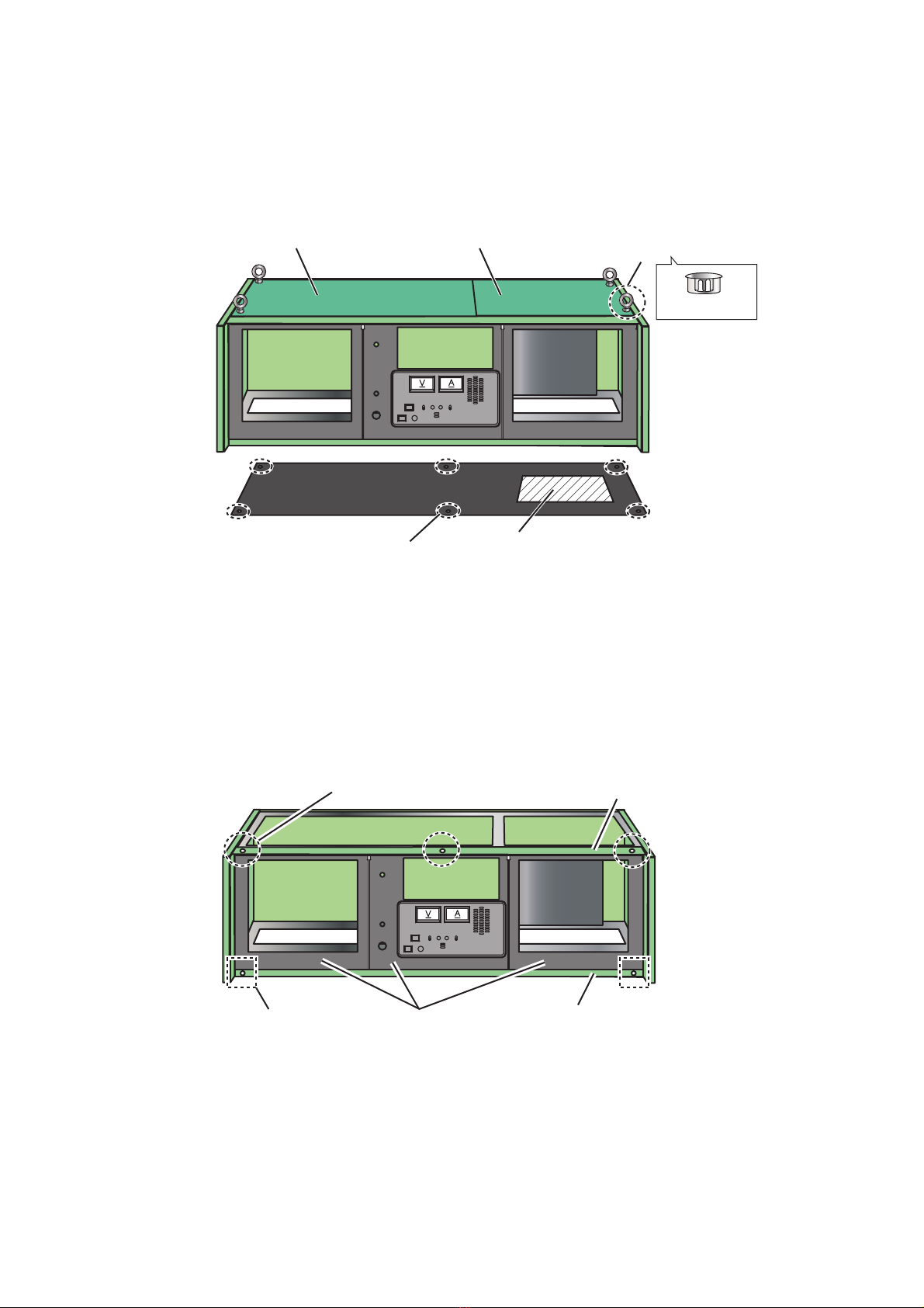
1.2 Rack Console Installation ..................................................................................................1-2
1.3 Terminal Unit (IC-218/IB-585)............................................................................................1-3
1.4 SSB Radiotelephone (FS-1575/FS-2575)..........................................................................1-4
1.5 Printer (PP-520) .................................................................................................................1-7
1.6 Fuse Box (SB-180) ............................................................................................................1-8
1.7 Distress Alert/Received Call Unit (IC-305)/Alarm Unit (IC-350).........................................1-8
1.8 Alarm Unit (IC-306)............................................................................................................1-8
1.9 SSAS Alert Unit (IC-307) ...................................................................................................1-9
1.10 AC/DC Power Supply Units (PR-300/PR-850)...................................................................1-9
1.11 Other Equipment................................................................................................................1-9
2. WIRING....................................................................................................................2-1
2.1 Wiring Diagram ..................................................................................................................2-1
2.2 Location of Terminal Blocks Inside the Rack Console.......................................................2-2
2.3 Connection of Equipment Installed in the Console ............................................................2-2
2.4 Connection of External Equipment ....................................................................................2-3
2.5 Fuse Box (SB-180) ............................................................................................................2-6
2.6 Charger Unit (BC-6158-SS/6200) ......................................................................................2-7
2.7 Power Supply Unit (PR-300/PR-850A) ..............................................................................2-9
3. CHECKING OPERATION........................................................................................3-1
3.1 Checking Operation of Equipment .....................................................................................3-1
3.2 General Check ...................................................................................................................3-1
APPENDIX 1 JIS CABLE GUIDE .............................................................................AP-1
PACKING LISTS ......................................................................................................... A-1
OUTLINE DRAWINGS ................................................................................................ D-1
INTERCONNECTION DIAGRAM ................................................................................ S-1

The paper used in this manual
is elemental chlorine free.
・FURUNO Authorized Distributor/Dealer
9 52 Ashihara cho,
Nishinomiya, 662 8580, JAPAN
A
:
APR
2015
.
Printed in Japan
All rights reserved.
B1
:
JAN
.
07, 2021
Pub. No.
IME-56331-B1
(
TAYA
)
RC-1800T-75
0 0 0 1 9 0 4 8 6 1 1

i
SAFETY INSTRUCTIONS
The installer must read the applicable safety instructions before attempting to install the equipment.
Indicates a potentially hazardous situation which, if not avoided,
could result in death or serious injury.
WARNING
Indicates a potentially hazardous situation which, if not avoided,
can result in minor or moderate injury.
CAUTION
Prohibitive Action Mandatory Action
WARNING CAUTION
Use only the specified power cable.
Fire or damage to the equipment can
result if a different cable is used.
Use the correct fuse.
Use of a wrong fuse can result in
damage to the equipment.
Turn off the power at the mains
switchboard before beginning the
installation.
Fire, electrical shock or serious injury
can result if the power is left on or is
applied while the equipment is being
installed.
Handle copper plate carefully.
Sharp edges can cut fingers.
Ground the equipment to prevent
electrical shock and mutual
interference.
Observe the following safe compass
distances to prevent interference to a
magnetic compass:
Standard
compass
Steering
compass
4.75 m 3.15 m
RC-1800T

ii
SYSTEM CONFIGURATION
Whip Antenna
(2.6 m)
Ship’s Mains
100/110/220 VAC,
1φ, 50/60 Hz
Antenna Coupler
AT-1575/5075
•
SSB Transceiver Unit:
FS-1575T/FS-2575T
•
SSB Control Unit:
FS-2575C
•
Printer Interface:
IF-8500
•
Terminal Unit:
IC-218, IB-585*2
•
Printer:
PP-520
*
1
: Equipment installed in the console
24 VDC
SSB Radiotelephone*1
Control Unit
SSB Radiotelephone*1
Control Unit
LED Flexible
Light
NLFL-03W-WB
(max. 2)
LED Flexible
Light
NLFL-03W-WB
(max. 2)
SSB Radiotelephone*1
Handset
SSB Radiotelephone*1
Handset
*2: IB-585 not required for dual Inmarsat-C
installation.
*3: Two antenna units required for dual
Inmarsat-C installation.
*4: SB-180 is required for proper operation.
GMDSS Radio Station
RC-1800T
Terminal Unit*1
Terminal Unit*1
Terminal Unit*1
Terminal Unit*1
: Optional or local supply
Antenna Unit*2
IC-118
Pre-Amp
FAX-5
• Distress Alert/Received
Call Unit IC-305 or
Alarm Unit IC-350 (max. 2)
• Alarm Unit IC-306 (max. 3)
• SSAS Alert Unit IC-307
(max. 3)
Printer*1
PP-520
Printer*1
PP-520
Fuse Box*4
SB-180
Rectifier
PR-850A
AC/DC
Power Supply
Unit
PR-300
Charger Unit
BC-6158-SS/6200

iii
EQUIPMENT LISTS
Standard Supply
*: See the list for the installation materials at the back of this manual.
Optional Supply
For equipment installed in the console
This console needs the following equipment. For the installation and the system configuration of
the equipment, see their operator’s and installation manuals.
• SSB Radiotelephone (FS-1575/FS-2575)
• Inmarsat-C MES (FELCOM18)
• Printer (PP-520)
Name Type Code No. Qty Remarks
Main Frame MA-1800T-75-Y — Select
one.
Standard color, w/ IF-8500
MA-1800T-75-T — Specified color, w/ IF-8500
Spare Parts SP05-06401* 001-380-060 1
Installation Materials CP05-13400 000-027-521 1 CP05-13401* (for main frame)
CP05-13402* (for SSB transceiv-
er unit)
Name Type Code No. Qty Remarks
LED FLEXIBLE LIGHT NLFL-03W-WB 001-197-170 1 Max. 2

EQUIPMENT LISTS
iv
This page is intentionally left blank.

1-1
1. INSTALLATION
1.1 Installation Considerations
Install the rack console where the equipment in the console can be easily operated,
checked and serviced. Consult with shipyard personnel and ship’s officer-in-charge to
determine best location. The location must satisfy the following points:
• Observe the compass safe distances in the "SAFETY INSTRUCTIONS" on page i
to prevent interference to a magnetic compass.
• Consider relation to other equipment near the console.
• Leave sufficient space around the unit for maintenance and servicing. See the con-
sole outline drawing for recommended maintenance space.
• Select a location where the vibration is minimal.
• Locate the console away from places subject to water splash and rain.
• The temperature and humidity of the location should be both stable and moderate.
• If the rack console is to be installed in the radio room, the units shown below must
be installed on the bridge.
• Distress Alert/Received Call Unit: IC-305
• Alarm Unit: IC-306
• SSAS Alert Unit: IC-307
• The recommended torques for the screws used in the system are as shown in the
table below.
Parts to be obtained locally
*: DPYC-35: The sectional area is 35 mm2.
Size of screw Torque
M3 0.78 N•m
M4 2.26 N•m
M5 4.51 N•m
M6 7.65 N•m
Unit Parts Qty Manual reference
Rack Console Bolt (M10u30 or longer) 6 page 1-2
Charger Unit Bolt (M6u30 or longer) 4 page 1-10
Fuse Box Cable (DPYC-35*) 2 page 2-6
Cable (DPYC-6) 1 page 2-6
NOTICE
Do not apply paint, anti-corrosive sealant or contact spray to
coating or plastic parts of the equipment.
Those items contain organic solvents that can damage coating and
plastic parts, especially plastic connectors.

1. INSTALLATION
1-2
1.2 Rack Console Installation
Leave at least 100 mm of service space on the sides and at the rear of the console.
Determine cable coming position and size referring to the illustration below. See "How
to fasten the earth plate" on page 1-3 for the ground location. Determine size of the
cable coming considering both cable size and cable bends.
1. If the eyebolts are attached on the top cover (to hoist the console), remove the
eyebolts after hoisting then attach the four hole plugs, supplied with CP05-13401.
2. Remove the screws on the top covers (right and left, a total of eight screws) to re-
move the top covers.
3. Use six bolts (locally supplied, M10u30 or longer) to fasten the console from the
inside of the console.
4. Remove three bolts (M5) on the top cover (front) then remove the top cover (front).
5. Remove the two screws (M5) on the front cover to remove the front cover.
6. Unfasten two bolts (M5) on the top and two bolts (M5) on the bottom of each panel
to remove three front panels.
7. Install and connect the equipment in the console. For the installation and wiring
for each equipment, see the applicable sections in this chapter.
8. Attach the front panels.
9. Attach the covers (front cover and three top covers).
Mounting location
Mounting location
Fixing holes 6-ø12 (6 places)
Remove eyebolts and cover
with four hole plugs.
Cable entrance
(See the outline drawings.)
Top cover (left) Top cover (right)
Hole Plug
Front cover
Top cover (front)
Bolt (three pcs.)
Screw (2 pcs.) Front panel (3 pcs.)

1. INSTALLATION
1-3
How to fasten the earth plate
Weld a steel plate with earth plate,
and connect it to the rack console.
Solder the point where the earth
plate connects to the grounding lo-
cation, to prevent corrosion and to
ensure tight connection.The earth
plate is included in CP05-13401.
1.3 Terminal Unit (IC-218/IB-585)
The figure below shows the locations for the terminal units in the console.
Install the terminal units as follows.
*1: A 3A fuse (for IB-585) is provided in the fuse holder on the power cable. (The fuse
holder is located inside the wiring duct.) If IC-218 (2nd) is installed instead of IB-585,
replace the fuse with 7A fuse. Then attach the appropriate label to the fuse holder. The
7A fuse and fuse label are included in installation materials CP05-13401.
*2: When IB-585 is installed, the JUNCTION connector for IC-218, connected at the
factory, is not required. Store the JUNCTION connector in the wiring duct, referring to
the figure on page 1-3.
CAUTION
Ground the equipment to prevent
electrical shock and mutual
interference.
Handle copper plate carefully.
Sharp edges can cut fingers.
Grounding locationGrounding location
Wiring ductWiring duct
Copper plate
Steel plate
(Weld to ship’s hull)
Side to be attached to
the console
How to prepare earthing
IC-218 IB-585*2
or
IC-218 (2nd)*1
Front Panel

1. INSTALLATION
1-4
1. Remove the front panels, referring to step 6 on page 1-2.
2. Put the terminal units in the front panels from the front side.
3. Fasten the four M4 screws (supplied) on the rear of each front panel.
1.4 SSB Radiotelephone (FS-1575/FS-2575)
1.4.1 Control unit (FS-2575C)
Fasten the control unit as follows.
1. Remove the front panels, referring to step 6 on page 1-2.
Note: Be careful not damage wiring inside the console when unfastening the front
panel.
2. Put the control unit in the console from the front side.
3. Fasten the two M6 screws (supplied) on the rear of the front panel.
1.4.2 Handset (HS-2003)
Attach the handset on the same front panel as the control unit.
1. Remove the front panels, referring to step 6 on page 1-2.
Note: Be careful not damage wiring inside the console when unfastening the front
panel.
Terminal Unit
(rear side)
Screw, 4 pcs.
Front Panel (rear side)
Control Unit
FS-2575C
Control PanelFront Panel
Bolts (2 pcs.)
Front panel (rear side)
Control Unit
(rear side)

1. INSTALLATION
1-5
2. Remove six bolts (M4) on the hanger cover of the handset.
3. From the front side of the front panel, fasten the hanger plate to the fixing holes
with the two bolts (M4) which are attached on the panel.
1.4.3 Transceiver unit (FS-1575T/FS-2575T)
1. Attach the stay (supplied) to the inside of the transceiver unit.
1) Remove the M4 screws (FS-1575T: three screws, FS-2575T: four screws) on
the transceiver unit as follows to open the radiator plate.
Handset
Handset
Hanger Cover
Hanger Cover
Hanger cover (side view) Hanger cover (front view)
Six screws to remove Hanger Plate
Control Unit Control Unit
Fixing locations (2 places) Handset
Bolts (2 pcs., attached on the panel)
Hanger Plate
Three screws
Ex): FS-1575T
Radiator plate

1. INSTALLATION
1-6
2) Attach the stopper support (supplied) to the upper side of the transceiver unit
with the two screws (M3u8, supplied). Then attach the rod guides to the stop-
per support.
3) Close the radiator plate.
2. Install the transceiver unit to the inside of the console.
1) Remove four screws (M5) on the top and bottom of the support plate (left) to
remove the support plate (left).
2) For FS-1575T, change the location for the fixing plate (left) as follows. For FS-
2575T, the plate may be left in the original position.
3) Remove two M5 screws on the fixing plate (right and left).
Upper side Top view
Stopper support 䋨supplied䋩
Two screws
(M3×8, supplied)
Rod guide
䋨supplied䋩
Rod guide
䋨supplied䋩
Support plate (left)
Four screws
Fixing plate (left)
Original fixing holes
M5 screw
M5 screw
Fixing plates

1. INSTALLATION
1-7
4) Set the transceiver unit such that the cable entrance of the transceiver unit
faces to the right, then set the transceiver unit to the console.
5) Put the transceiver unit on the fixing plates (right and left), then push the trans-
ceiver unit into the console until the unit contacts the stoppers.
6) Fasten the transceiver unit to the fixing plates with two M5 screws removed at
step 3). For the fixing locations, see the outline drawings of FS-1575T or FS-
2575T.
1.5 Printer (PP-520)
Fasten the printer PP-520 after the installation of the other equipment is completed.
For how to fasten the printer, see the outline drawing at the back of this manual and
the operator’s manual of the printer. Observe the compass safe distances in the
"SAFETY INSTRUCTIONS" on page i to prevent interference to a magnetic compass.
Extract the power cables and signal cables to be connected to the printer from the
grommet on the top cover. Attach the fixtures (supplied in the installation materials of
PP-520) to the top cover. Connect the cables to the printer. Adjust the size of the exit
for cables on the grommet then reattach the grommet.
Stopper (2 pcs.)Stopper (2 pcs.)
Fixing plate (right
and left)
Fixing plate (right
and left)
Cable entrance side
Transceiver UnitTransceiver Unit
M5 ScrewM5 Screw
Printer

1. INSTALLATION
1-8
1.6 Fuse Box (SB-180)
The fuse box must be installed to protect the equipment installed in the console from
overcurrent. Install the fuse box where it is easy to access.
Remove the four M4 screws on the cover. Fasten the fuse box to the installation loca-
tion from the inside with the self-tapping screws, supplied in CP05-08701. See the out-
line drawing for details.
1.7 Distress Alert/Received Call Unit (IC-305)/Alarm
Unit (IC-350)
Select the installation locations where the buttons on the IC-305 and IC-350 can be
operated easily in an emergency. For how to install these units, see the installation
manual of Inmarsat-C (FELCOM18).
1.8 Alarm Unit (IC-306)
The IC-306 releases the audio alarm and flashes the lamp in its ALARM RESET but-
ton when a telex or e-mail is received. For how to install these units, see the installa-
tion manual of Inmarsat-C (FELCOM18).
Top cover (left) GrommetGrommet
Remove the grommet.
Cable (No.1 printer)Cable (No.1 printer)
Cable (No.2 printer)Cable (No.2 printer)
Power cable
Signal cableSignal cable
Attach the grommet.
Attach the grommet.
M4 screw (4 pcs.)
Self-tapping screws
(supplied, ø4×20, 4 pcs.)
Cable entrance
Cover

1. INSTALLATION
1-9
1.9 SSAS Alert Unit (IC-307)
Select the installation location where the buttons on the IC-307 can be operated easily
in an emergency and is difficult to find by an intruder. Let the captain and the qualified
persons only know the installation location of the unit. For how to install the unit, see
the installation manual of IC-307.
1.10 AC/DC Power Supply Units (PR-300/PR-850)
The PR-300 and PR-850A supply both AC and DC power. Install the power supply
units outside the console considering the following requirements.
• Select a location where vibration is minimal.
• The location should be moderate and stable in both temperature and humidity.
• The installation location must be able to support the weight of the unit.
1.11 Other Equipment
1.11.1 LED flexible light (optional, max. 2)
Fasten the LED flexible light (NLFL-03WWB, max 2) on the top cover (left).
1. Remove four screws (M3) on the cover to
remove the cover.
2. Remove the bottom plate from the light assy. The bottom plate may be discarded.
Top cover (left)
Fixing location
LED flexible light (option, max. 2)
Fixing position
Cover
Light assy.
Discard this part
after removing.
Bottom plate
Light

1. INSTALLATION
1-10
3. Fasten the light from the top with the screws removed at step 1.
1.11.2 Charger Unit (BC-6158-SS/6200)
Fasten the charger unit (option) considering the following points.
• Select a location where vibration is minimal.
• The location should be moderate and stable in both temperature and humidity.
• The installation location must be able to support the weight of the unit.
• The location must be at least seven meters from a magnetic compass.
1. Remove four screws on the front panel then
remove the front panel.
2. Unfasten the screws fixing the charger unit. Pull the unit forward with the handle.
3. Fasten the case of the charger unit
from the top of rail with four screws
(M6u15 or longer, local supply).
4. Push the charger unit in until it contacts the stoppers. Fasten the unit to the rail
with the two screws prefastened to the rail, at the cutout location.
5. Attach the front panel.
Charger Unit (Front view)
Front panelFront panel
Four screws
Charger Unit
Pull forward.
Handle
Handle
Two screws to unfasten
(right and left)
Two screws to unfasten
(right and left)
Fixing holes
(4 places, right
and left)
Rail
StopperStopper
Fasten at the cutout of the
charger unit (two places,
right and left).
Fasten at the cutout of the
charger unit (two places,
right and left).

2-1
2. WIRING
2.1 Wiring Diagram
Inmarsat-C
8D-FB-CV 50 m
No.2 VHF
FM-8900
No.1 VHF ANT
AM radio
FAX
RG-10/UY
No.1 VHF
ANT WR
RG-10/UY
TTYCSLA-1
(AF LINE OUT)*
1
(AF LINE OUT)*
1
DPYC-1.5 (BK)*
1
TTYCSLA-1
MPYC-4 (BK)*
1
(GPS data NMEA0183)
Common BATT
TTYCSLA-1
Charger Unit
BC-6158-CC/6200
Fuse Box
SB-180
Reverse
Source BATT
200AH
05S0952/05S0793
5%
Cable attenuation 25sq 14 m
(max. 50A) 35sq 19 m
50sq 27 m
RC-1800TRC-1800T
No.1 VHF
FM-8900
FAX
Public
addressor
LED Light
(1w/10w)
LED Light
(1w/10w)
TTYC-4S
RG-10U
Output
RG-10U
TTYC-4S
GPS
ANT/MC
No.2 VHF ANT RG-10/UY
(BK)
*
1
: BK, AK Line OUT can be relayed
existing rack console.
*
2
: The sectional area is 35 mm
2
.
PR-850A
PR-300
DSC ANT
No. 1 Printer
PP-520
No. 2 Printer
PP-520
RG-10/U-Y
FAX-5
DPYC-4 (24 V/Back up)
TTYCSLA-1 (NAV data)
DPYC-4 (2 4V/Back up)
Antenna Coupler
AT-1575(FS-1575)
AT-5075(FS-2575)
Automatic
Antenna Switch
AS-102
Ship’s Mains
100/110/220 VAC
1ø, 50/60 Hz
DPYC-6
DPYC-2.5
DPYC-35*
2
DPYC-16
DPYC-16/
DPYC-10/
DPYC-1.5
TPYC-1.5
05S9486
10S1197
MPYC-7
DPYC-6
DPYC-35*
2
MF/HF
ANT
Wing MIC
or
Wing Handset
HS-6000FZ11
(10 m cable)
TTYC
SLA
-4
TTYC
SLA
-4
TTYC
SLA
-4
Distress Alert/Received Call Unit (IC-305), Alarm Unit (IC-350)
Alarm Unit (IC-306)
SSAS Alert Unit (IC-307)
: Coaxial connector
: Connector

2. WIRING
2-2
2.2 Location of Terminal Blocks Inside the Rack
Console
The figure below shows the location of the terminal blocks inside the console.
Terminal blocks (Top view)
The locations for terminal blocks are shown in the figure below.
2.3 Connection of Equipment Installed in the Con-
sole
For connections at the equipment side, see respective installation manuals.
• FELCOM18: Installation Manual (IME-56740-x)
• FS-1575/FS-2575: Installation Manual (IME-56770-x)
• PP-520: Operator’s Manual (OMC-50802-x)
The terminal blocks TB1 to TB4 have cables preattached, and the cables destinations
are marked on the cables. For the printer cables, pull them out from the grommet on
the top cover of the console then connect them to the printer. See section 1.5.
Terminal Block (TB1 - TB4)
TB1: For power cable
TB2 - TB4: For signal cable
TB1
TB2 TB3 TB4

2. WIRING
2-3
2.4 Connection of External Equipment
Pass the cables of external equipment through the cable entrance at the bottom of the
console. Connect the cable to terminal blocks TB1 to TB4, referring to this section and
the interconnection diagram.
Connect the cables of external equipment to the terminal blocks (TB1 to TB4) through
the cable entrance at the bottom of the console.
2.4.1 Terminal block TB1
2.4.2 Terminal block TB2
Terminal
no. Destination Signal line
1 to 2
PR-850A
Back-up DC LINE IN (#1: (+), #2: (-))
3 to 4 DC LINE OUT (#3: (+), #4: (-))
5 to 6 AC FAIL (#5: (+), #6: (-))
7 to 8 PR-300 Back-up DC LINE IN (#7: (+), #8: (-)
9 to 10 No.1 VHF DC LINE OUT (w/Back-up) (#9: (+), #10: (-))
11 to 12 No.2 VHF DC LINE OUT (w/Back-up) (#11: (+), #12: (-))
13 to 15 Fuse Box
16 to 17 — NC
18
Charger
Unit
CHARGE
19 to 20 BATT OUT (#19: (+), #20: (-))
21 24 VDC
22 0 VDC
127 8
3 4 9 10 11 12
5 6 13 14 15 16 17 18 19 20 21
22
23
PR-850A PR-300
#1 to #6
VHF
#9 to #12
#7 to #8
Fuse Box
#13 to #15
Battery Charger
#18 to #22
LED flexible light
#1 to #4
VHF
#18 to #21
BAM
#23 to #31
#15, #16
FAX GPS
#5 to #13
7 85 6
3
4
12
15 1613 1411 12910 23 2421 2219 2017 18 29 30
31 32
27 2825
26
Insert cores (Either entrance is available).

2. WIRING
2-4
BK connection (Standard)
Terminal
no. Destination Signal line
1 to 4 LED flexible light #1 to #2: For Light 1, #3 to #4: Light 2
5 to 7 No.1 FAX BK OUT (#5: DC (+), #6: BK (-), #7: DC (-))
8 to 9 No.2 FAX BK OUT (#8: DC (+), #9: BK (-)
10 to 11 No.1 FAX AF LINE OUT (#10: (H), #11: (C))
12 to 13 No.2 FAX AF LINE OUT (#12: (H), #13: (C))
14 Shield
15 to 16 GPS Position data IN
17 Shield
18 to 19 No.1 VHF Position data OUT
20 to 21 No.2 VHF
22 — NC
23 to 24 BAM AC_FAIL
25 to 26 LOW_VOLT
27 NC
28 to 29 BUZZER STOP
30 to 31 BRIDGE ALARM
32 NC
CAUTION
Before wiring an external radiotelephone, confirm that
the BK DC- is not connected to RF ground, referring
to the circuit diagram.
The SSB radiotelephone may become damaged if the BK
DC- is connected to RF ground.
TB2
No.1 FAX BK DC+ BK LINE IN
No.1 FAX BK-
No.1 FAX BK DC-
No.2 FAX BK DC+
No.2 FAX BK-
Receivers
(BK-)
BK Circuit
Detector*
Transmitters
RC-1800T
(BK DC-)
BK DC+
BK RELAY
No.1 FAX
BK-
(BK DC+)
*: To connect transmitter or other maker’s equipment,
contact your dealer to request connection of BK circuit.
BK DC+
BK RELAY
BK-
5
6
7
8
9
NOTE: BK control
current Max. 1 A
Other manuals for RC-1800T
2
Table of contents
Other Furuno Radio manuals

Furuno
Furuno FS-1503EM Owner's manual

Furuno
Furuno RB-700 User manual

Furuno
Furuno RC-1800F2 Series User manual

Furuno
Furuno RO-6700 User manual

Furuno
Furuno RC-1800F2 Series User manual

Furuno
Furuno RC-1800F User manual

Furuno
Furuno RC-1500-1T User manual

Furuno
Furuno FM-3000 User manual

Furuno
Furuno FS-5075 User manual

Furuno
Furuno RB-700 User manual