Furuno RC-1800F2 Series User manual

www.furuno.co.jp
A
ll brand and product names are trademarks, registered trademarks or service marks of their respective holders.
INSTALLATION MANUAL
GMDSS Radio Station RC-1800F2
SAFETY INSTRUCTIONS............................................................................i
SYSTEM CONFIGURATION.......................................................................ii
EQUIPMENT LISTS....................................................................................iv
1. MOUNTING.........................................................................................1-1
1.1 Mounting Considerations..........................................................................................1-1
1.2 Mounting the Channel Base and Rack Console........................................................1-3
1.3 Mounting the Rack Console Table, Keyboard...........................................................1-5
1.4 Mounting the Printer PP-510.....................................................................................1-6
1.5 Mounting the SSAS Alert Unit IC-307........................................................................1-7
1.6 Connection of Antenna Cable for DSC Function.......................................................1-8
1.7 Lamp Assembly (Option)...........................................................................................1-9
2. WIRING...............................................................................................2-1
2.1 Wiring Diagram..........................................................................................................2-1
2.2 Terminal Wiring .........................................................................................................2-2
2.3 Connection of External Equipment............................................................................2-6
2.4 JIS (Japan Industrial Standards) Cable Data............................................................2-8
3. CHECKING OPERATION...................................................................3-1
3.1 Checking Operation of Equipment.............................................................................3-1
3.2 General Check...........................................................................................................3-1
3.3 Instructions for Cancelling Distress Alert...................................................................3-5
PACKING LIST........................................................................................A-1
OUTLINE DRAWINGS............................................................................. D-1
INTERCONNECTION DIAGRAM............................................................ S-1

Thepaperusedinthismanual
iselementalchlorinefree.
・FURUNOAuthorizedDistributor/Dealer
9‑52Ashihara‑cho,
Nishinomiya,662‑8580,JAPAN
Telephone: +81‑(0)798‑65‑2111
Fax:
+81‑(0)798‑65‑4200
A
:
MAY
2008
PrintedinJapan
Allrightsreserved.
C
:
OCT
.
05,2009
Pub.No.
IME‑56640‑C
*00016903512**00016903512*
(
HIMA
)
RC‑1800F2
*
00016903512
*
*
00016903512
*
*00016903512*

i
SAFETY INSTRUCTIONS
WARNING
ELECTRICAL SHOCK HAZARD
Do not open the equipment
unless totally familiar with
electrical circuits and
service manual.
Only qualified personnel
should work inside the
equipment.
Turn off the power at the switchboard
before beginning the installation.
Fire or electrical shock can result if the
power is left on.
CAUTION
Ground the equipment to
prevent electrical shock and
mutual interference.
RC-1800F2 3.7 m 2.5 m
Standard
compass Steering
compass
Observe the following safe compass
distances to prevent deviation of
a magnetic compass:

ii
SYSTEM CONFIGURATIONS
RC-1800F2-1S/2S/5S
RC-1800F2-1S: FS-1570, one FELCOM 15
RC-1800F2-2S: FS-2570, one FELCOM 15
RC-1800F2-5S: FS-5070, one FELCOM 15
Printer
PP-510
Inmarsat-C
Antenna Unit
IC-115
Printer
PP-510
SSB Radiotelephone
FS-1570, 2570 or 5070
NBDP Terminal Unit
IB-583
Inmarsat-C
FELCOM15
Terminal Unit
AC-DC Power
Supply Unit
PR-240 (No.1 to No.4,
w/back-up)
AC-DC Power
Supply Unit
PR-850AR (w/back-up)
Battery Charger
BC-6158-SS
Antenna Coupler
AT-1560-15
(for 150 W)
AT-1560-25
(for 250 W)
AT-5000
(for 500 W)
Preamp
FAX-5
Whip Antenna
04S4176
100/110/220 VAC, 1
φ
, 50/60 Hz
24 VDC
SSB Antenna
-Distress Alert/Received
Call Unit IC-305
-Alarm Unit IC-306
-SSAS Alert Unit IC-307
AC-DC Power
Supply Unit
PR-240 (No.5, w/o back-up)
Control Unit
FS-2571C
Automatic
Antenna
Switch
AS-102

iii
RC-1800F2-1D/2D/5D
RC-1800F2-1D: FS-1570, two FELCOM 15
RC-1800F2-2D: FS-2570, two FELCOM 15
RC-1800F2-5D: FS-5070, two FELCOM 15
Printer
PP-510
Antenna Coupler
AT-1560-15
(for 150 W)
AT-1560-25
(for 250 W)
AT-5000
(for 500 W)
Inmarsat-C
Antenna Unit
IC-115
Printer
PP-510
Control Unit
FS-2571C
SSB Radiotelephone
FS-1570, FS-2570 or FS-5070
Inmarsat-C
FELCOM 15 (No. 2)
Terminal Unit
Inmarsat-C
FELCOM15
Terminal Unit
AC-DC Power
Supply Unit
PR-240 (No.1 to No.4,
w/back-up)
AC-DC Power
Supply Unit
PR-850AR (w/back-up)
Battery Charger
BC-6158-SS
Preamp
FAX-5
Whip Antenna
04S4176
-Alarm Unit IC-306
-Distress Alert/Received
Call Unit IC-305
-SSAS Alert Unit IC-307
100/110/220 VAC, 1
φ
, 50/60 Hz
24 VDC
SSB Antenna
AC-DC Power
Supply Unit
PR-240 (No.5, w/o back-up)
Automatic
Antenna
Switch
AS-102

iv
EQUIPMENT LISTS
Standard Supply
Components of rack console
Name Type Code No. Qty Remarks
Rack Console RC-1800F2 - 1 See table below.
Antenna Unit IC-115 - 1 For 2D type, two units are supplied.
Antenna Coupler AT-1560-15 - 1 For FS-1570
AT-1560-25 - For FS-2570
AT-5000 - For FS-5070
Printer PP-510 - 2
Distress Alert/
Received Call Unit IC-305 - 1 or 2 FELCOM 15, two units are supplied
for 2D.
Alarm Unit IC-306 - 1 or 2 FELCOM 15, two units are supplied
for 2D.
SSAS Alert Unit IC-307 - 1 or 2 FELCOM 15, two units are supplied
for 2D.
Installation Materials CP05-11600 000-012-611 1 set CP16-02302, CP05-09301
Spare Parts SP05-05901 001-037-750 1 set
Accessories FP05-06200 000-012-612 1 set Mini keyboard, Floppy disk, paper
FP05-06300 000-013-175 1 set FP05-06301, 06302, 06304, 06305
FP05-06310 000-013-176 FP05-06301, 06312, 06314, 06315
Name Type Code No. Qty Remarks
Main Frame MA-1800F2 - 1
Terminal Unit IB-583 - 1 or 0 For NBDP
IC-215 - 1 or 2 For FELCOM 15
Transceiver Unit for
SSB Radiotelephone FS-1570T - 1 150 W
FS-2570T - 250 W
FS-5070T - 500 W
AC-DC Power Supply
Unit PR-240 - 5
PR-850AR - 1
Battery Charger BC-6153A - 1 For 100 VAC
BC-6153B - For 220VAC
BC-6158-SS - For 100/220 VAC
Printer Interface IF-8500 - 1
Control Unit FS-2571C - 1 w/Handset HS-2003

v
Option
Name Type Code No. Qty Remarks
Preamp Unit FAX-5 - 1
Distress Alert Unit IC-302-DSC 1
Incoming indicator IC-303-DSC 1
BK Interface BK-300 1
Antenna Unit IC-115 - 1
Distress Alert/Received
Call Unit IC-305 - 1
Alarm Unit IC-306 - 1
SSAS Alert Unit IC-307 - 1
EGC Printer PP-505 - 1
Control Unit FS-2571C - 1
Antenna BK Relay OP05-35-H 000-056-878 1
GPS Board Kit OP16-47 001-017-110 1
Watch Receiver Kit OP05-104 001-004-450 1
Signal Splitter OP05-103 005-965-780 1
Terminal Software 16-5-0164 004-438-920 1
PC Terminal Software OP16-45 004-449-600 1
SSAS Modification Kit OP16-33 000-043-492 1
Flush Mount Kit OP05-98 005-951-830 1 For No.2 FS-2571C
OP16-27 004-448-000 1 For IC-305/306
OP16-28 004-448-010 1 For IC-307
Russian Kit OP16-43 004-449-590 1 For FELCOM15
Key Template OP05-101 004-447-450 1 For FS-5070
Antenna Installation Kit CP16-03701 004-555-000 1 For FELCOM15
Antenna Mounting Pipe CP16-03703 001-014-510 1 For FELCOM15
Antenna Mounting Metal CP16-03702 001-016-260 1 For FELCOM15
Matching Box ARD-1 005-502-230 1 For FS-5070

vi
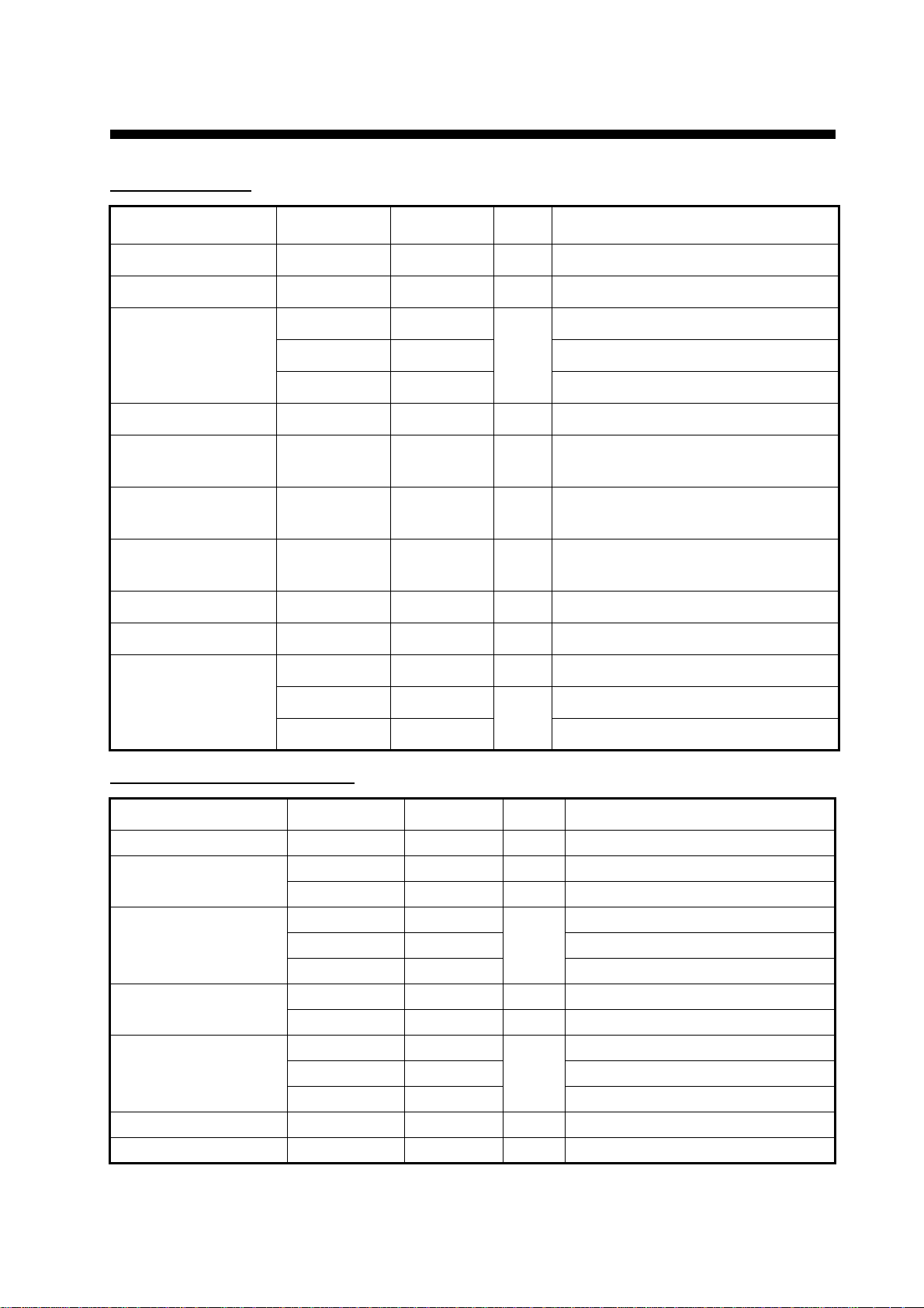
Installation Materials CP24-00151 005-931-190 1 For PR-240
CP16-03620 000-043-648 1 50 m, w/pipe, for FEL-
COM15
CP05-09010 005-954-180 1 10 m cable set
CP05-09020 005-964-410 1 25 m cable set
CP05-09030 001-079-290 1 10 m cable set
CP05-09040 001-079-320 1 25 m cable set
CP16-03610 000-043-647 1 30 m, w/pipe, for
FELCOM15
CP16-03630 000-043-649 1 100 m, w/pipe, for
FELCOM15
CP16-03650 000-043-650 1 30 m, for FELCOM 15
CP16-03660 000-043-651 1 50 m, for FELCOM 15
CP16-03670 000-043-652 1 100 m, for FELCOM 15
E-22 000-050-632 1 For FS-5070
E-24 000-050-634 1 For FS-5070
E-25 000-050-635 1 For FS-5070
E-26 000-050-636 1 For FS-5070
E-27 000-050-637 1 For FS-5070
Instrument 4-0555 005-547-130 1
Tool 4-0554 005-547-140 1
UR-72 000-058-878 1
External Loudspeaker SEM-21Q 000-144-917 1
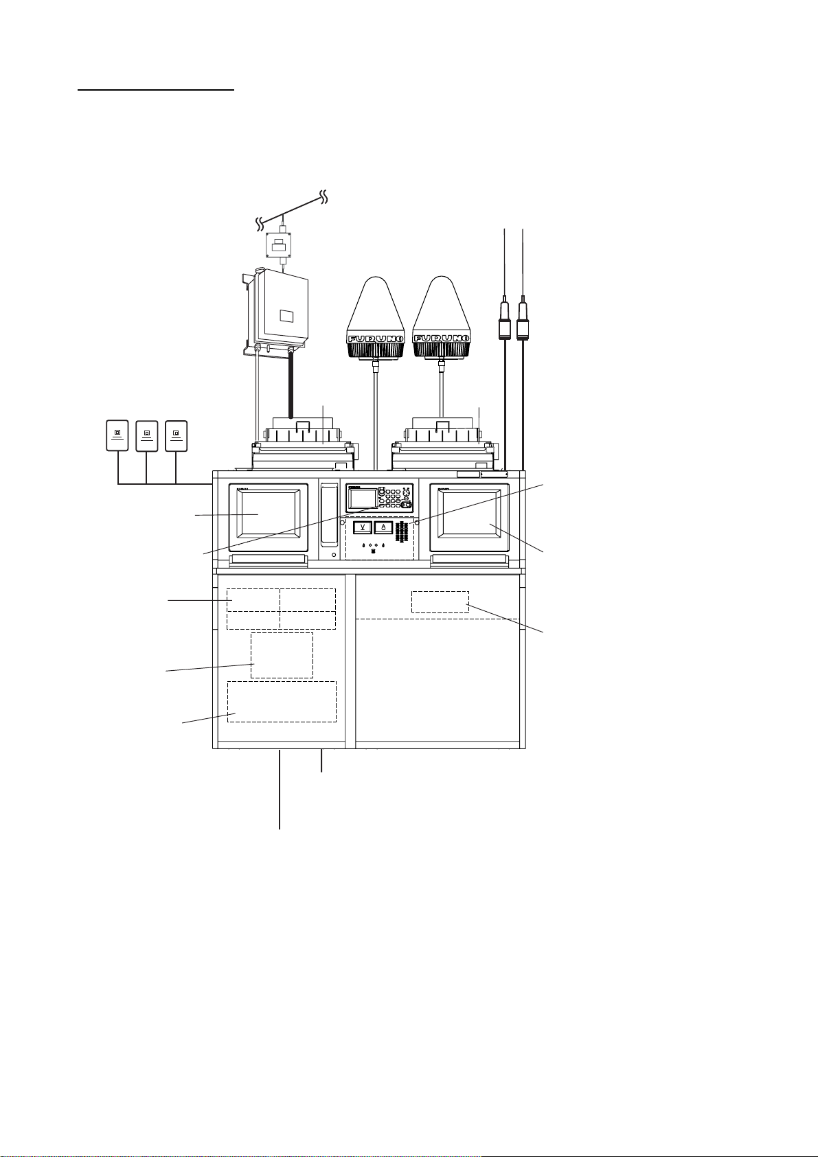
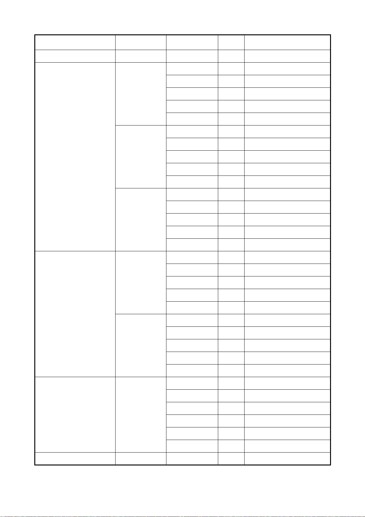
Antenna Junction Box AJB1-1A 000-870-284 1 w/CP16-01200, FP16-00100
Emergency Light EMG-1T 000-138-378 1
Lamp Assembly L3/12-YLP2 000-169-005-10 1
Electric Torch BN121F 000-808-415 1
Recording Paper A2 1PLYW 000-167-226-10 1 roll
Ribbon Cassette SP-16051NB 000-133-029 1
Freestanding Antenna AS-9 000-105-818 1
Antenna AT130 000-137-233 1
AT101D/S2 000-139-314 1
Antenna Elevating Unit MT-100 000-137-231 1
T-AS-9 000-105-819 1
Name Type Code No. Qty Remarks

vii
Strain Insulator YT-180 #18 000-166-342-10 1
5P Cable 05S0309 000-106-043-10 1 10 m
000-106-044-10 1 20 m
000-106-046-10 1 30 m
000-106-047-10 1 40 m
000-106-048-10 1 50 m
05S0793 000-125-984-10 1 10 m
000-125-986-10 1 20 m
000-125-987-10 1 30 m
000-125-988-10 1 40 m
000-125-989-10 1 50 m
COSPEVVSBC
5PX0.2LF 000-560-452-10 1 10m, for FELOCOM 15
000-103-868-10 1 20 m, for FELOCOM 15
000-103-869-10 1 30 m, for FELOCOM 15
000-132-829-10 1 40 m, for FELOCOM 15
000-132-828-10 1 50 m, for FELOCOM 15
Coaxial Cable RG-10/U-Y 000-159-411-10 1 10 m
000-159-412-10 1 20 m
000-159-413-10 1 30 m
000-159-414-10 1 40 m
000-159-415-10 1 50 m
RG-8A/U 000-167-213-10 1 10 m
000-167-214-10 1 20 m
000-106-054 1 30 m
000-106-055 1 40 m
000-106-056 1 50 m
Cable Assy. 17JE23150-02
(D8C) 000-146-015 1 5 m
000-146-016 1 10 m
000-146-017 1 20 m
000-146-018 1 30 m
000-146-019 1 40 m
000-146-020 1 50 m
Clock KS474M 000-166-300-10 1
Name Type Code No. Qty Remarks

viii
Cable Assy. 17JE23150-
02 (D8C) 000-146-015 1 5 m
000-146-016 1 10 m
000-146-017 1 20 m
000-146-018 1 30 m
000-146-019 1 40 m
000-146-020 1 50 m
Clock KS474M 000-166-300-10 1
Multimeter CX-506A 000-150-468 1
SP-21 000-165-303 1
Aerometer No. 4 000-440-516 1
Thermometer -20C.-100C 000-440-517 1
Lamp NL-54
AC110V E-26 000-542-672 1
Tool Set S-10 000-830-251 1
Lead-in Insulator YA-218 000-166-558-10 1
YA-256 000-571-433 1
YA-347 000-571-434 1
Automatic Antenna
Switch AS-102 - 1
Name Type Code No. Qty Remarks

1-1
1. MOUNTING
1.1 Mounting Considerations
1.1.1 Mounting considerations for RC-1800F2
As shown on the next page, the rack console is normally installed on the bridge.
Install the rack console where the equipment can be easily operated, checked and serviced. Con-
sult with shipyard personnel and ship’s officer-in-charge to determine best location. The location
must satisfy the following points:
• Consider relation to other equipment near mounting site and mounting direction.
• Select a location where controls can be easily operated.
• Ample space should be left at the sides of the equipment to enable servicing and to provide
ventilation.
• Select a location where shock and vibration are minimal.
• Locate the console away from water splash and rain.
• The temperature and humidity of the location should be both stable and moderate.
• If the rack console is to be installed in the radio room, Distress Alert/Received Call Unit IC-305,
Alarm Unit IC-306, SSAS Alert Unit IC-307 and EGC Printer PP-505 must be installed on the
bridge.
• The performance of a magnetic compass will be affected if placed too close to the rack con-
sole. Separate the rack console from a compass by the distances shown on page i to prevent
compass error.
As for mounting the antenna coupler and antenna units, refer to the respective Installation Manu-
als.

1-2
SSB Antenna
No.1 FM-8800
and EMG Lamp
No.1 VHF Antenna
No.2 VHF Antenna
No.1 VHF Watch Antenna
MF /HF
Watch Antenna
Inmarsat C
Antenna
-5 deg.
NAV data
Cont/RF
BK/AF
8D-FB-CV 50m
BOW
BOW
MIC
MIC
BATT24V
100/200
VAC
NAVTEX Antenna
FAX-5
NX-5
X-band Radar
Antenna
BK
Rx Antenna
FAX Antenna
AM Radio Antenna
Rx Antenna
No.2 VHF
Clock
SART
SART
IC-305
Wing MIC
GPS
Wing MIC
EPIRB
Main Power
RC-1800F2
FAX NAVTEX
No.2 FM-8800
and EMG Lamp
AT-1560
Coupler
24V/NAV data
FM-8 x 3 sets
Two-way
Radiotelephone
with batt charger
NX-700 NAVTEX
TBR-500 / 300 / 200 x 2 sets
KANNAD 406 WH
GMDSS General Wiring Scheme
BATT charger, NBDP Terminal,
Power supply, SSB Radiotelephone,
Inmarsat-C Receiver, Printer x 2 sets
RC-1800F2 Configuration

1-3
1.2 Mounting the Channel Base and Rack Console
Leave at least 100 mm of service space on the sides and at the rear of the console. Determine
cable coming position and size and ground location by referring to the figure below. Determine
size of the cable coming considering both cable size and cable bends.
Weld all sides of the channel base to the deck. Fasten the rack console to the channel base with
six M12 bolts.
After leading in cables through the rear of the rack console, cover cable entrances with putty or
silicone sealant to close any gaps.
Note: After removing four hoisting eyebolts from the rack console, cover the four holes for the eye-
bolts with the cosmetic caps (installation materials: CP05-09301).
CAUTION
Ground the equipment to
prevent electrical shock and
mutual interference.
Handle copper plate carefully.
An edge of it may harm your
hand.
Service Space
100 mm
Service SpaceService Space
100 mm Hex Bolt
Note: Cable entrance at bottom of console. Determine
the cable coming location considering frame position,
cable layout and total sectional area of cabling.
Note: After welding and painting
with rust inhibiting paint, paint
same color as console
(Munsell 7.5BG7/2).
Rear cable entrance
67x200 mm, 2 places
If necessary cables can
be led in through the
rear of the channel
base.
Cable Entrance 465x422 mm
Copper Plate Support
Steel plate with
copper plate 0.4x50x600 mm
Fixing Hole
RC-1800F2 Remove eyebolts and
cover with four cosmetic caps.
(Installation Materials: CP05-09301)
100 mm
(
φ
15, 6 places)
(M12, 6 pcs., local supply)

1-4
Grounding the copper plate
Weld a steel plate with copper strap, and connect it to the rack console. Solder the point where
the copper plate connects to the copper platge support, to prevent corrosion and to ensure tight
connection.
Ground the equipment to
prevent interference and
CAUTION
electrical shock.
Soldering Copper plate
Weld to ship’s
hull.
Steel plate
Silver alloy
brazing
0.4x50x600 mm
Connect to
the copper plate
support.

1-5
1.3 Mounting the Rack Console Table, Keyboard
1. Fasten right and left side table brackets to the console frame with six M5x20 bolts supplied as
accessories.
2. Lay the rack console table on the top of the table brackets.
3. Fasten the rack console table with five M6x15 flat head screws.
*=M5x20 bolt (w/spring washer and flat washer)
The keyboard for the terminal unit can be fastened to the tabletop.
1. Cut the rubber cap at the front of the console beneath the No.1/No.2 IC-215 or IB-583, and
pass the printer cable through it.
2. Unfasten two screws (M4x10) to detach the front cover.
Table Bracket
(Right)
Table Bracket
(Left)
Flat Head Screw Bolt*
Bolt
Rack Console
Table
Flat Head
Screw
Flat head
Screw
Rubber cap
M6 bolt M6 bolt
M4x10
screw
M4x10
screw
Front cover

1-6
3. Unfasten two hex. bolts (M6) to open the front panel of the rack console.
Note: Lock the stay at the left-hand side inside the rack console.
4. Connect the keyboard connector to the rear of the IC-215/IB-583.
5. Remount the front panel and the front cover.
6. Fix the keyboard to the tabletop with fastener (3) and fastener (4), supplied with the installa-
tion materials CP16-02302.
1.4 Mounting the Printer PP-510
1. Place the printers on the top of the rack console. Connect printer connector and printer power
cord to printers.
2. Set printer fixing plates (one each for left and right sides of printer) to printer and fix them to
the rack console with M4x10 screws.
LOCK
Stay
Rack console, opening the front panel
Printer Fixing Plate (2)
FP05-06315/06305
24 VDC
24 VDC
Screw M4x10,
4 pcs.
Printer Fixing Plate (1)
Screw
M4x10,
4 pcs. Printer Fixing
Plate (2)
Printer Fixing Plate (1)
FP05-06314/06304
PP-510
(For Inmarsat-C)
PP-510
(For DSC/NBDP or
No.2 Inmarsat-C)

1-7
1.5 Mounting the SSAS Alert Unit IC-307
Select the mounting location where the button on the unit can be operatedeasily in an emergency.
See the back of this manual for mounting dimensions and recommended clearance space.
For cabling, use a cable entrance at the front or bottom of the rack console depending on the
mounting location. For the cable entrance at the front of the rack console, cut the rubber cap to
use it.
Cable entrances

1-8
1.6 Connection of Antenna Cable for DSC Function
1.6.1 Installation of antenna FAX-5
Fix the FAX-5 (preamp unit) to the mounting mast (diameter 35 to 90 mm) with hose clamps (In-
stallation material CP05-09301).Screwthe whip antenna(04S4176)intotheFAX-5.Coatconnec-
tion point with putty for waterproofing.
Switching to coaxial cable with armor
To switch to the coaxial cable with armor (RG-10/UY);
1. Remove 15 to 25 cm of the sheath of the cable RG-10/UY and attach connector MP-7 (Instal-
lation material CP05-09301) to the cable.
2. Attach the connector FMA-1 between connectors MP-3 and MP-7.
3. Cover connectors with self-vulcanizing tape followed by vinyl tape to waterproof.
The coaxialcables RG-10/UY from the preamp unitand the antennacoupler are connected tothe
MP-7 connectors inside the rack console.
J4 J3 J2 J1
from preamp FAX-5
from antenna coupler
(TX)
from antenna coupler
(RX, FS-5070 only)
from antenna
unit IC-115 from antenna unit IC-115
(when No.2 FELCOM 15
is mounted)
RC-1800F2, front view
Set spring washer to 2.6 meter whip antenna and
MP-3
MP-7
(Installation
material)
FMA-1
(Installation
material) MP-7
(installation material)
Bond flat mesh wire to
RG-10/UY
Waterproofing
(Self-vulcanizing tape and vinyl tape)
Attach MP-7 connector to
Ground for FAX-5
Mast (
φ
35-90 mm)
Parker Clamp
FAX-5
for FS-2570
w/optional PCB
screw antenna into preamp unit.
(Inst. Materials CP08-0061)
(Drill hole in mast;
fasten ground wire
with M4 screw.)
shield and ground
near cable entrance on
rack console.
coaxial cable and connect
to MR relay connector.

1-9
1.7 Lamp Assembly (Option)
The lamp assembly (type: L3/12-YLP2, code no.: 000-169-005-10) is optionally available. Mount
it as follows.
1. Unfasten two M3 screws from the top of the rack console.
2. Unscrew two M3 screws to remove the bottom plate from the lamp assembly.
3. Use two screws unfastened at step 1 to fasten the bottom plate for the lamp assembly to the
top of the rack console.
4. Reattach the lamp assembly to the bottom plate.
5. Unfasten two pan head screws to detach the plate that partially covers the cable entrance
behind the printer on the right-side.
6. Pass the power cable from the lamp assembly through the cable entrance.
7. Re-attach the plate to the cable entrance.
8. Open the front panel, and connect the power cable from the printer lamp and the connector
located at right-hand side in the rack console.
9. Close the front panel.
Cable entrance
M3 Screw
(4 pcs.)
Bottom plate
Printer lamp
Power cable
(into the cable entrance)
Connector for
printer lamp power cable
(inside)
Plate

1-10
This page is intentionally left blank.
Other manuals for RC-1800F2 Series
2
Table of contents
Other Furuno Radio manuals

Furuno
Furuno RC-1500-1T User manual

Furuno
Furuno RC-1800F2 Series User manual

Furuno
Furuno FS-5075 User manual

Furuno
Furuno RB-700 User manual

Furuno
Furuno RC-1800F2 Series User manual

Furuno
Furuno FM-3000 User manual

Furuno
Furuno RC-1800F User manual

Furuno
Furuno FS-1503EM Owner's manual

Furuno
Furuno RO-6700 User manual

Furuno
Furuno RB-700 User manual