Furuno RC-1800F2 Series User manual

www.furuno.com
All brand and product names are trademarks, registered trademarks or service marks of their respective holders.
INSTALLATION MANUAL
GMDSS Radio Station
Model RC-1800F2
SAFETY INSTRUCTIONS ............................................................................ i
SYSTEM CONFIGURATION ....................................................................... ii
EQUIPMENT LISTS.................................................................................... iv
1. MOUNTING.........................................................................................1-1
1.1 Mounting Considerations..........................................................................................1-1
1.2 Mounting the Channel Base and Rack Console........................................................1-3
1.3 Mounting the Rack Console Table, Keyboard ...........................................................1-5
1.4 Fixing the Slide Rail KC-252-20 ................................................................................1-6
1.5 Mounting the Printer PP-520 .....................................................................................1-7
1.6 Mounting the SSAS Alert Unit IC-307........................................................................1-7
1.7 Connection of Antenna Cable for DSC Function .......................................................1-8
1.8 Lamp Assembly (Option) ...........................................................................................1-9
2. WIRING ...............................................................................................2-1
2.1 Wiring Diagram..........................................................................................................2-1
2.2 Terminal Wiring .........................................................................................................2-2
2.3 Connection of External Equipment ............................................................................2-6
2.4 Charger Unit BC-6158-SS .........................................................................................2-8
2.5 JIS (Japan Industrial Standards) Cable Data ..........................................................2-11
3. CHECKING OPERATION...................................................................3-1
3.1 Checking Operation of Equipment.............................................................................3-1
3.2 General Check...........................................................................................................3-1
3.3 Instructions for Cancelling Distress Alert...................................................................3-5
PACKING LISTS...................................................................................... A-1
OUTLINE DRAWINGS............................................................................. D-1
INTERCONNECTION DIAGRAMS.......................................................... S-1
The paper used in this manual
is elemental chlorine free.
・FURUNO Authorized Distributor/Dealer
9 52 Ashihara cho,
Nishinomiya, 662 8580, JAPAN
A
:
MAY
2008
Printed in Japan
All rights reserved.
Q
:
SEP
.
13, 2018
Pub. No.
IME-56640-Q
(
ETMI
)
RC-1800F2
0 0 0 1 7 8 8 5 1 1 4
i
SAFETY INSTRUCTIONS
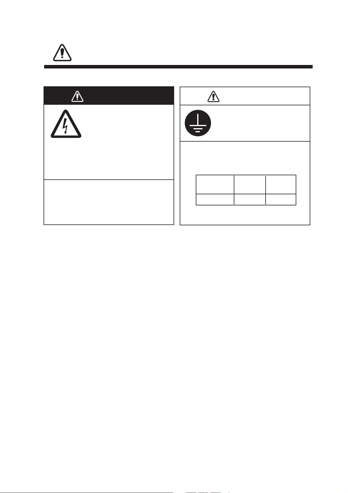
WARNING
WARNING
ELECTRICAL SHOCK HAZARD
Do not open the equipment
unless totally familiar with
electrical circuits and
service manual.
Only qualified personnel
should work inside the
equipment.
Turn off the power at the switchboard
before beginning the installation.
Fire or electrical shock can result if the
power is left on.
CAUTION
CAUTION
Ground the equipment to
prevent electrical shock and
mutual interference.
RC-1800F2 3.7 m 2.5 m
Standard
compass
Steering
compass
Observe the following safe compass
distances to prevent deviation of
a magnetic compass:
ii
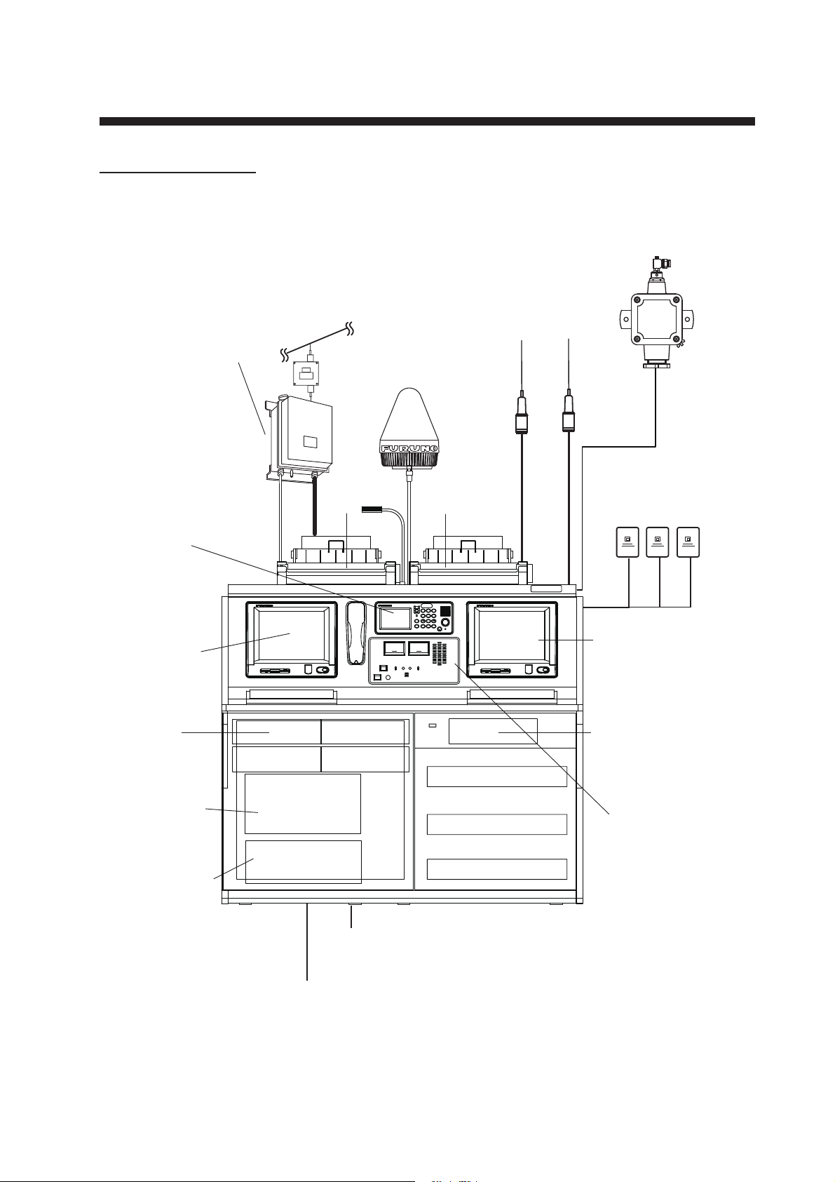
SYSTEM CONFIGURATIONS
RC-1800F2-1S/2S/5S
RC-1800F2-1S: FS-1575, one FELCOM 18
RC-1800F2-2S: FS-2575, one FELCOM 18
RC-1800F2-5S: FS-5075, one FELCOM 18
Printer
PP-520
Inmarsat-C
Antenna Unit
IC-118
Printer
PP-520
SSB Radiotelephone (inside)
FS-1575T/2575T/5075T
NBDP Terminal Unit
IB-585
Inmarsat-C
Terminal Unit
IC-218
AC-DC Power
Supply Unit*
PR-240 (No.1 to No.4,
w/back-up)
AC-DC Power
Supply Unit
PR-850AR
(w/back-up)
Battery Charger
BC-6158-SS
Antenna Coupler
AT-1575
(for FS-1575)
AT-5075
(for FS-2575/5075)
Preamp
FAX-5
Whip Antenna
04S4176
100/110/220 VAC, 1
φ
, 50/60 Hz
24 VDC
SSB Antenna
-Distress Alert/Received
Call Unit IC-305
-Alarm Unit IC-306
-SSAS Alert Unit IC-307
AC-DC Power
Supply Unit*
PR-240 (No.5, w/o back-up)
Control Unit
FS-2575C
(for FS-1575/
2575/5075)
Antenna
Switch
AS-102
DISTRESS
CANCEL
CALL
1
RT
GHI
IntCom
4
PQRS
7
*
FILE
CURSOR
ABC
DSC
2
JKL
ACK/SQ
5
PRINT
TUV
8
LOG
0
TUNE
DEF
TEST
3
MNO
SCAN
6
WXYZ
9
SETUP
#
CH
ALARM
OVEN
OFF
3:592/
PUSH TO ENTER
㹔㸿
ARD-1/AJB1-1A
(option)
*: AC-DC power supply unit No.4 and No.5 are not required
for FS-1575/2575.
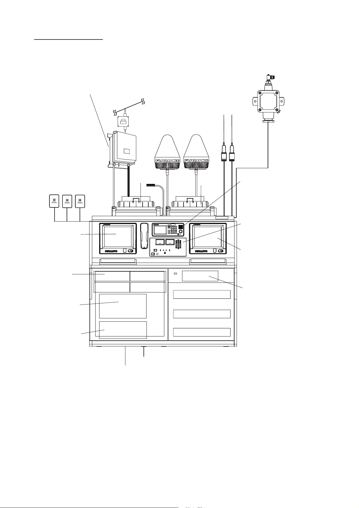
SYSTEM CONFIGURATIONS
iii
RC-1800F2-1D/2D/5D
RC-1800F2-1D: FS-1575, two FELCOM 18
RC-1800F2-2D: FS-2575, two FELCOM 18
RC-1800F2-5D: FS-5075, two FELCOM 18
Printer
PP-520
Antenna Coupler
AT-1575
(for FS-1575)
AT-5075
(for FS-2575/5075)
Inmarsat-C
Antenna Unit
IIC-118
Printer
PP-520
No. 2 Inmarsat-C
Terminal Unit
IC-218
No.1 Inmarsat-C
Terminal Unit
IC-218
AC-DC Power
Supply Unit*
PR-240 (No.1 to No.4,
w/back-up)
AC-DC Power
Supply Unit
PR-850AR
(w/back-up)
Battery Charger
BC-6158-SS
Preamp
FAX-5
Whip Antenna
04S4176
-Alarm Unit IC-306
-Distress Alert/Received
Call Unit IC-305
-SSAS Alert Unit IC-307 x 2
100/110/220 VAC, 1
φ
, 50/60 Hz
24 VDC
SSB Antenna
AC-DC Power
Supply Unit*
PR-240 (No.5, w/o back-up)
Antenna
Switch
AS-102
Control Unit
FS-2575C
(for FS-1575/2575/5075)
SSB Radiotelephone (inside)
FS-1575T/2575T/5075T
DISTRESS
CANCEL
CALL
1
RT
GHI
IntCom
4
PQRS
7
*
FILE
CURSOR
ABC
DSC
2
JKL
ACK/SQ
5
PRINT
TUV
8
LOG
0
TUNE
DEF
TEST
3
MNO
SCAN
6
WXYZ
9
SETUP
#
CH
ALARM
OVEN
OFF
3:592/
PUSH TO ENTER
㹔㸿
ARD-1/AJB1-1A
(option)
*: AC-DC power supply unit No.4 and No.5 are not required
for FS-1575/2575.

iv
EQUIPMENT LISTS
Standard Supply
Components of rack console
Name Type Code No. Qty Remarks
Rack Console RC-1800F2 - 1 See table below
Antenna Unit IC-118 - 1 or 2 Two units are supplied for 1D/2D/5D
Antenna Coupler AT-1575 - For FS-1575
AT-5075 - For FS-2575/5075
Printer PP-520 - 2
Distress Alert/
Received Call Unit
IC-305 - 1 or 2 Two units are supplied for 1D/2D/5D
Alarm Unit IC-306 - 1 or 2 Two units are supplied for 1D/2D/5D
SSAS Alert Unit IC-307 - 1 or 2 Two units are supplied for 1D/2D/5D
Installation Materials CP05-13300 000-022-721 1 set CP16-05202, CP05-09301
CP05-12501 001-169-290 1 set For FS-1575/2575/5075
Spare Parts SP05-05901 001-037-750 1 set
Accessories FP05-06200 000-012-612 1 set For IB-585
FP05-06300 000-013-175 1 set Color: Specified
FP05-06310 000-013-176 Color: 7.5BG
Name Type Code No. Qty Remarks
Main Frame MA-1800F2 - 1
Terminal Unit IB-585 - 1 or 0 For NBDP
IC-218 - 1 or 2 For FELCOM 18
Transceiver Unit for
SSB Radiotelephone
FS-1575T - 1 For FS-1575
FS-2575T - For FS-2575
FS-5075T - For FS-5075
AC-DC Power Supply
Unit
PR-240 - 3 or 5 5 sets for FS-5075
PR-850AR - 1
Battery Charger BC-6158-SS - 1 For 100/220 VAC
Printer Interface IF-8500 - 1
Control Unit FS-2575C - 1 For FS-1575/2575/5075,
w/Handset HS-2003

v
Option
Name Type Code No. Remarks
Control Unit FS-2575C - For FS-1575/2575/5075
Preamp Unit FAX-5 - w/cable 1/15m
BK Interface BK-300
Antenna Unit IC-118 - For FELCOM 18
Distress Alert/Received
Call Unit
IC-305 -
Alarm Unit IC-306 -
SSAS Alert Unit IC-307 -
Terminal Unit IB-585-A 000-020-895 For NBDP
External Loudspeaker SEM-21Q 001-165-970-10
Connector Set (RG10/U) OP05-124 001-135-620 For FS-1575/2575/5075
GPS Board Kit OP16-62 001-180-100 For FELCOM 18
Watch Receiver Kit OP05-123 001-135-610 For FS-1575/2575/5075
Full Duplex Kit OP05-125 001-135-630 For FS-5075
Waterproof Kit OP05-126 001-148-880 For FS-2575C
OP16-67 001-189-380 For IC-305/306
OP16-68 001-189-400 For IC-307
Terminal Software OP16-57 001-180-050 For FELCOM 18
Flush Mount Kit OP05-122 001-135-600 For No.2 FS-2575C
OP16-27 004-448-000 For IC-305/306
OP16-28 004-448-010 For IC-307
Key Template OP05-135 001-184-560 For IB-585
Antenna Cable
Extension Kit
OP04-2 *10M* 000-041-174 10 m
OP04-2 *20M* 000-041-175 20 m
OP04-2 *30M* 000-041-176 30 m
OP04-2 *40M* 000-041-177 40 m
OP04-2 *50M* 000-041-178 50 m
Hose Clamp OP08-11 005-954-696 For FAX
Earth Plate 0.4X50X600 000-170-971-10
Antenna Mounting Pipe CP16-05602 001-189-620 For FELCOM18
Matching Box ARD-1 005-502-230 For FS-5075

vi
Antenna Base
w/Hose Clamp
OP16-72 001-313-420 For IC-118
Antenna Base
w/Mount Pipe
OP16-73 001-313-430
Antenna Base w/U Bolt OP16-74 001-313-440
Antenna Base OP16-75 001-313-450
Installation Materials CP24-00151 005-931-190 For PR-240
CP05-09010 001-388-190 10 m cable set
CP05-09020 001-388-250 25 m cable set
CP05-09030 001-388-160 10 m cable, Antenna switch set
CP05-09040 001-388-150 25 m cable, Antenna switch set
CP16-05750 000-021-704 30 m cable (w/o armor), for
FELCOM18
CP16-05760 000-021-713 50 m, for FELCOM18
CP16-05770 000-021-714 100 m, for FELCOM18
CP16-05790 000-021-715 30 m, for FELCOM18
Antenna Materials E-24 000-050-634
E-25 000-050-635
E-26 000-050-636
E-27 000-050-637
Accessories FP05-04200 000-057-693 Printer paper A2 1PLYW
Instrument 4-0555 005-547-130
Antenna Junction Box AJB1-1A 001-255-690 w/CP16-01200, FP16-00100
Lamp Assembly L3/12-YLP2 000-169-005-11 For printer lamp
Electric Torch BL123F-P(H) 000-170-682-10
Ribbon Cassette 7Q1VP80SF 001-198-190-10 For PP-520
Name Type Code No. Remarks

vii
Whip Antenna FAW-6D
3-110682-00
000-572-128
FAW-6RP2 000-572-109
04S4176 001-153-112
WH-027-10M 001-139-400-10 10 m
FAW-6R2 000-572-108
FAW-6R2A 000-107-921
WH-027-8M 001-138-110-10
WH-027-8M02 001-138-120-10
WH-027-8M03 001-138-140-10
Strain Insulator YT-180 #18 000-166-342-10
Manual Tilting Mechanism WH-027-KD 001-139-410-10
WH-027-KD2 001-141-850-10
5P Cable 05S0793 000-125-984-10 10 m
000-125-986-10 20 m
000-125-987-10 30 m
000-125-988-10 40 m
000-125-989-10 50 m
COSPEVVSBC
5PX0.2LF
000-560-452-11 10m, for FELCOM 18
000-103-868-11 20 m, for FELCOM 18
000-103-869-11 30 m, for FELCOM 18
000-132-829-11 40 m, for FELCOM 18
000-132-828-11 50 m, for FELCOM 18
7C Cable 05S0952 000-758-821-10 10 m, for FS-1575/2575/5075
000-758-822-10 20 m, for FS-1575/2575/5075
000-758-823-10 30 m, for FS-1575/2575/5075
000-758-824-10 40 m, for FS-1575/2575/5075
000-758-825-10 50 m, for FS-1575/2575/5075
Coaxial Cable RG-10/U-Y 000-159-411-14 10 m
000-159-412-14 20 m
000-159-413-14 30 m
000-159-414-14 40 m
000-159-415-14 50 m
Name Type Code No. Remarks

viii
Coaxial Cable RG-8A/U 000-167-213-10 10 m
000-167-214-10 20 m
000-169-060-10 30 m
000-169-062-10 40 m
000-169-064-10 50 m
Cable Assy. DSUB15-5P 001-146-850-10 For FS-1575/2575/5075, 5 m
001-146-860-10 For FS-1575/2575/5075, 10 m
001-146-870-10 For FS-1575/2575/5075, 20 m
001-146-880-10 For FS-1575/2575/5075, 30 m
001-146-890-10 For FS-1575/2575/5075, 40 m
001-146-900-10 For FS-1575/2575/5075, 50 m
57FE-17JE-
BC10PL3000
000-174-473-10 For PP-520
Wire Rope Assy. TM-173-D4
L1520Y8
001-175-210-10 For FS-1575
TM-173-D4
L1670Y8
000-175-179-10 For FS-2575
TM-173-D4
L1800Y8
000-175-178-10 For FS-5075
Clock KS474M 000-166-300-10
Multimeter PM3 000-191-341-10
Tool Set S-10FD 000-190-627-10
S-34-100FD 000-191-306-10 For AC100V
S-34-230FD 000-191-307-10 For AC230V
Lead-in Insulator YA-218 001-079-370-10
YA-256 001-079-380
YA-347 001-079-390
Automatic Antenna
Switch
AS-102 000-167-460
Antenna Switch AS1-1E 000-167-029-10
PP-520 Replacement Kit OP05-137-T 001-258-250 Paint color: Specified
OP05-137-B 001-258-260 Paint color: 7.5BG7/2
Operator’s Manual OME-56352-* 000-157-160-1* For IC-307 (USCG)
Name Type Code No. Remarks
Other manuals for RC-1800F2 Series
2
This manual suits for next models
6
Table of contents
Other Furuno Radio manuals

Furuno
Furuno RC-1500-1T User manual

Furuno
Furuno FS-1503EM Owner's manual

Furuno
Furuno FS-5075 User manual

Furuno
Furuno RB-700 User manual

Furuno
Furuno RC-1800T User manual

Furuno
Furuno RB-700 User manual

Furuno
Furuno RC-1800F User manual

Furuno
Furuno RO-6700 User manual

Furuno
Furuno FM-3000 User manual

Furuno
Furuno RC-1800F2 Series User manual


