Seite 4 | SkyWind Installaon Handbook
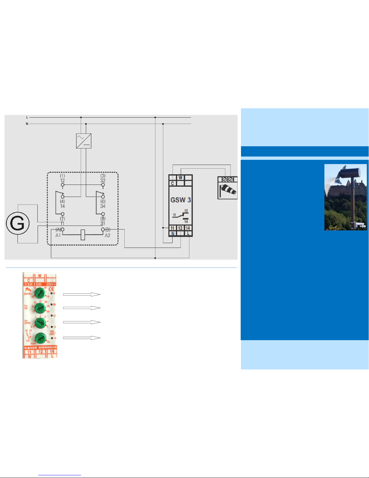
Turbine stop at 50 kph (recommended) | 70 kph (max.)
Turbine stop immediatly aer max. wind speed is reached
Turbine stop for ve (5) minutes aer max. wind speed is reached
Relais mode: hold
Every SkyWind NG turbine must be equip-
ped with an eecve storm protecon
system. For safety reasons this system
needs to be redundant.
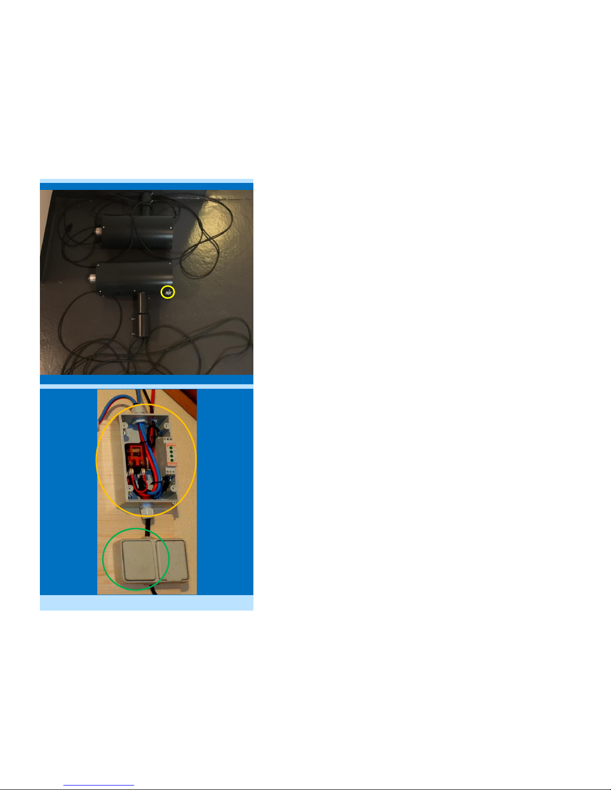
The alongside wiring layout must be in-
stalled by a professional electrician with
greatest care. The system is designed to
stop the turbine in case of a grid power
loss and in case of wind speeds above the
turbines limitaons.
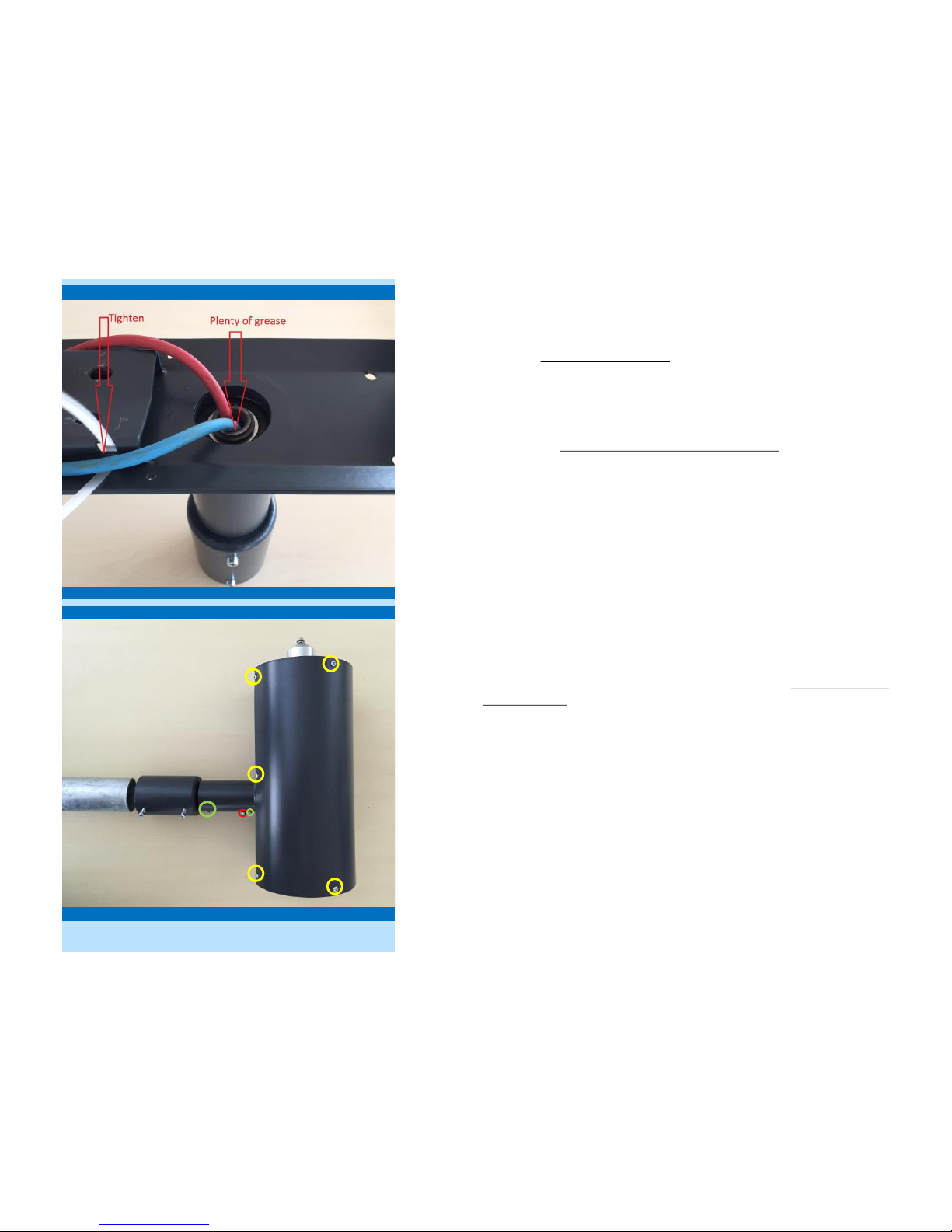
The storm control will stop the turbine by short-circuing the
turbines DC side. For this reason the poles Nr. (1) 12 and (3) 32
must be connected to each other.
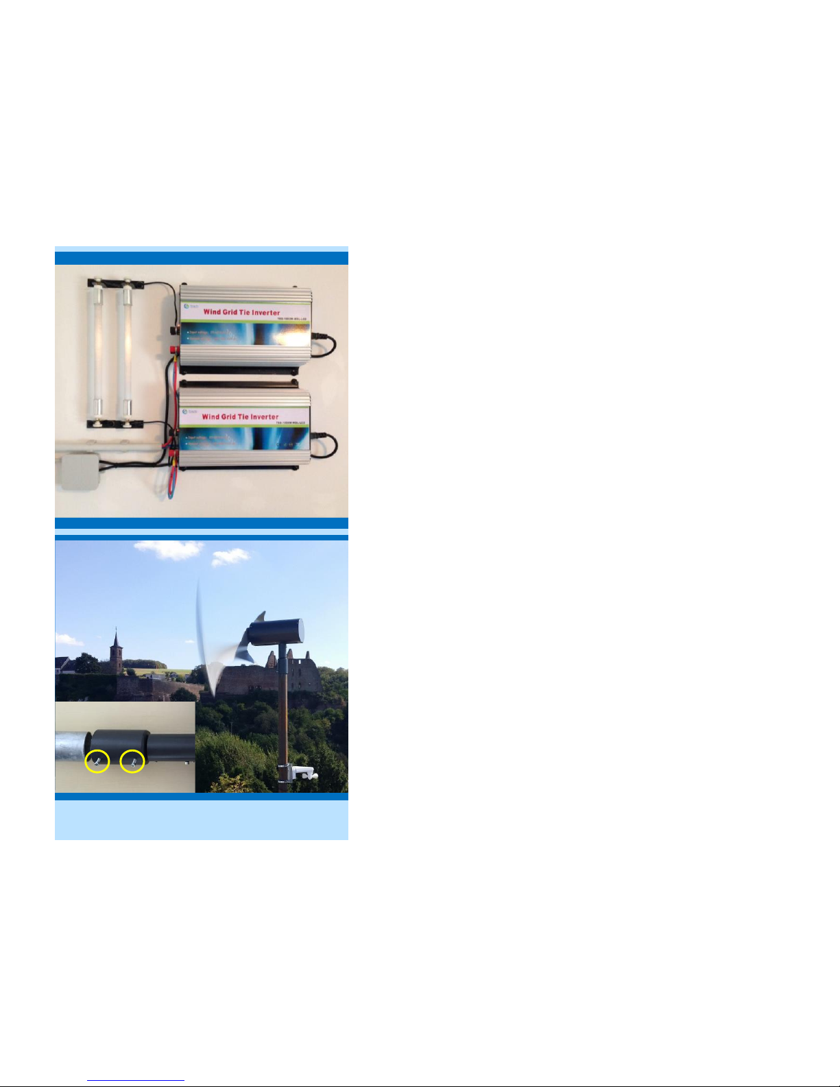
The wind sensor must be installed 0,20m below the rotor discs
lowest point on the mast of the wind turbine.
Aer installaon the system must be checked in two separate
ways:
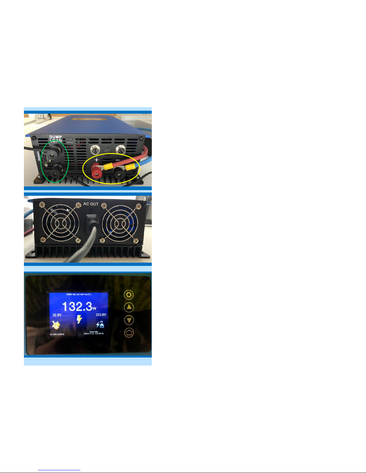
1. Shut o the turbines AC power. The rotor rotaon must
rapidly decrease immediatly.
2. Set the storm controls reacon wind speed to 10 kph. The
relay should now switch with a ‚klick‘ noise upon the
slightest breeze.
Regularily check the storm controls funcon to guarantee for a
safe and reliable operaon for years to come.
9. Automac Storm Control
Wiring Diagram
Page 7 | SkyWind Installaon Handbook
max. 35 m